check transmission fluid FORD FESTIVA 1991 Service Manual
[x] Cancel search | Manufacturer: FORD, Model Year: 1991, Model line: FESTIVA, Model: FORD FESTIVA 1991Pages: 454, PDF Size: 9.53 MB
Page 28 of 454
Back To Article
BRAKE SYST EM
1991-92 BRAKES Disc & Drum
DESCRIPTION & OPERATION
On Capri, vehicle braking is provided by front and rear disc brakes. Front and rear brakes are a full-floating, single piston design. The rear
caliper houses a self-adjusting parking brake.
On Festiva, vehicle braking is provided by front disc brakes and rear drum brakes. Rear brakes are a standard non-servo, self-en e r giz in g d e sign .
Front brakes are a full-floating, single piston design with caliper attached to steering knuckle.
BLEEDING BRAKE SYSTEM
BLEEDING PROCEDURES
Manual Bleeding
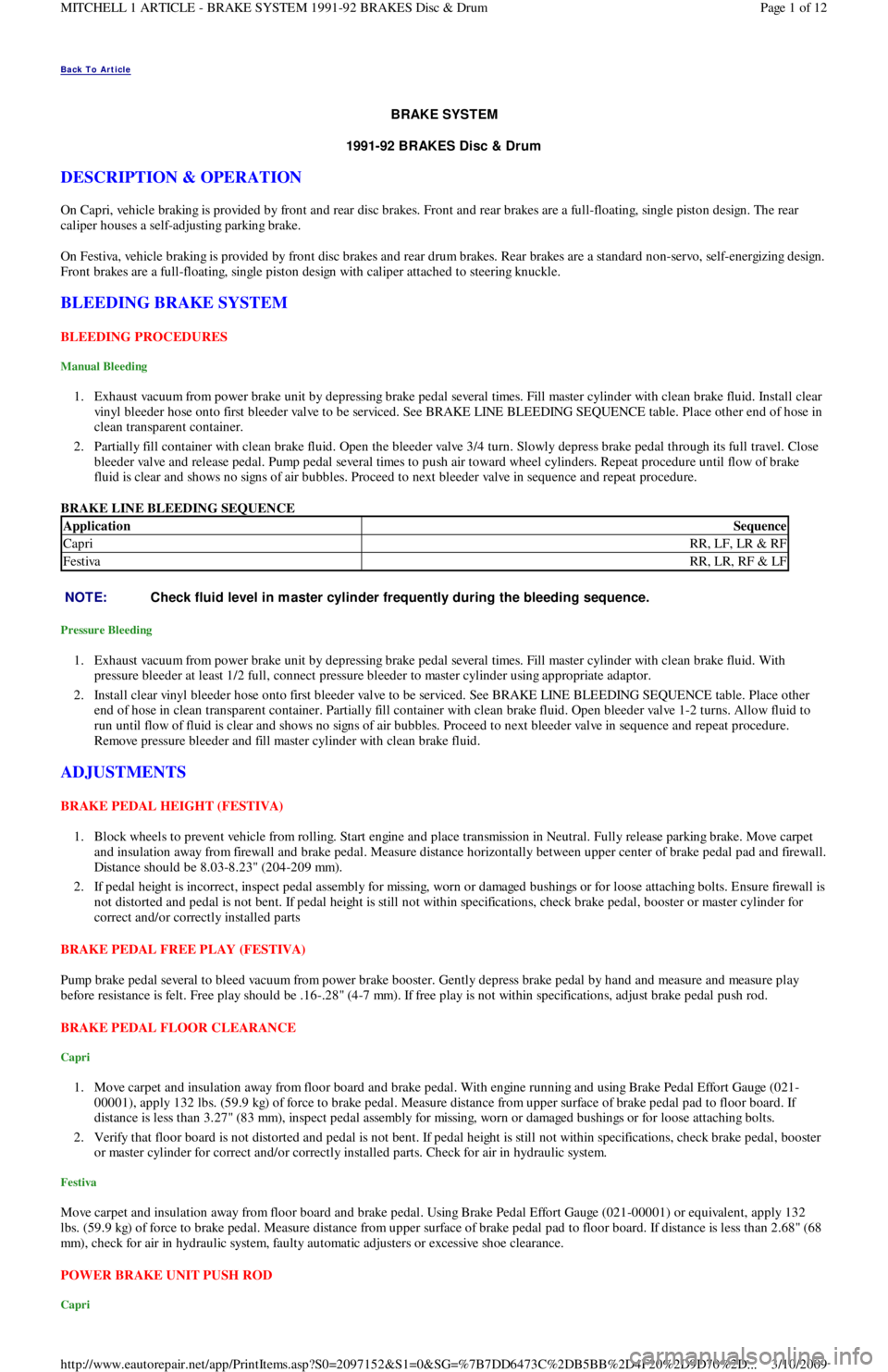
1. Exhaust vacuum from power brake unit by depressing brake pedal several times. Fill master cylinder with clean brake fluid. Install clear
vinyl bleeder hose onto first bleeder valve to be serviced. See BRAKE LINE BLEEDING SEQUENCE table. Place other end of hose in
clean transparent container.
2. Partially fill container with clean brake fluid. Open the bleeder valve 3/4 turn. Slowly depress brake pedal through its full travel. Close
bleeder valve and release pedal. Pump pedal several times to push air toward wheel cylinders. Repeat procedure until flow of brake
fluid is clear and shows no signs of air bubbles. Proceed to next bleeder valve in sequence and repeat procedure.
BRAKE LINE BLEEDING SEQUENCE
Pressure Bleeding
1. Exhaust vacuum from power brake unit by depressing brake pedal several times. Fill master cylinder with clean brake fluid. With
pressure bleeder at least 1/2 full, connect pressure bleeder to master cylinder using appropriate adaptor.
2. Install clear vinyl bleeder hose onto first bleeder valve to be serviced. See BRAKE LINE BLEEDING SEQUENCE table. Place other
end of hose in clean transparent container. Partially fill container with clean brake fluid. Open bleeder valve 1-2 turns. Allow fluid to
run until flow of fluid is clear and shows no signs of air bubbles. Proceed to next bleeder valve in sequence and repeat procedure.
Remove pressure bleeder and fill master cylinder with clean brake fluid.
ADJUSTMENTS
BRAKE PEDAL HEIGHT (FESTIVA)
1. Block wheels to prevent vehicle from rolling. Start engine and place transmission in Neutral. Fully release parking brake. Move carpet
and insulation away from firewall and brake pedal. Measure distance horizontally between upper center of brake pedal pad and firewall.
Distance should be 8.03-8.23" (204-209 mm).
2. If pedal height is incorrect, inspect pedal assembly for missing, worn or damaged bushings or for loose attaching bolts. Ensure firewall is
not distorted and pedal is not bent. If pedal height is still not within specifications, check brake pedal, booster or master cylinder for
correct and/or correctly installed parts
BRAKE PEDAL FREE PLAY (FESTIVA)
Pump brake pedal several to bleed vacuum from power brake booster. Gently depress brake pedal by hand and measure and measure play
before resistance is felt. Free play should be .16-.28" (4-7 mm). If free play is not within specifications, adjust brake pedal push rod.
BRAKE PEDAL FLOOR CLEARANCE
Capri
1. Move carpet and insulation away from floor board and brake pedal. With engine running and using Brake Pedal Effort Gauge (021-
00001), apply 132 lbs. (59.9 kg) of force to brake pedal. Measure distance from upper surface of brake pedal pad to floor board. If
distance is less than 3.27" (83 mm), inspect pedal assembly for missing, worn or damaged bushings or for loose attaching bolts.
2. Verify that floor board is not distorted and pedal is not bent. If pedal height is still not within specifications, check brake pedal, booster
or master cylinder for correct and/or correctly installed parts. Check for air in hydraulic system.
Festiva
Move carpet and insulation away from floor board and brake pedal. Using Brake Pedal Effort Gauge (021-00001) or equivalent, apply 132
lbs. (59.9 kg) of force to brake pedal. Measure distance from upper surface of brake pedal pad to floor board. If distance is less than 2.68" (68
mm), check for air in hydraulic system, faulty automatic adjusters or excessive shoe clearance.
POWER BRAKE UNIT PUSH ROD
Capri
ApplicationSequence
CapriRR, LF, LR & RF
FestivaRR, LR, RF & LF
NOTE:Check fluid level in m aster cylinder frequently during the bleeding sequence.
Page 1 of 12 MITCHELL 1 ARTICLE - BRAKE SYSTEM 1991-92 BRAKES Disc & Drum
3/10/2009 http://www.eautorepair.net/app/PrintItems.asp?S0=2097152&S1=0&SG=%7B7DD6473C%2DB5BB%2D4F20%2D9D70%2D
...
Page 411 of 454
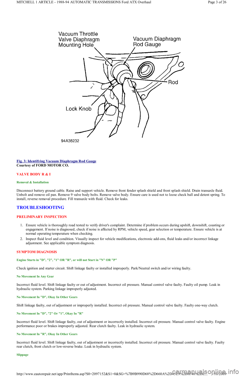
Fig. 3: Identifying Vacuum Diaphragm Rod Gauge
Courtesy of FORD MOTOR CO.
VALVE BODY R & I
Removal & Installation
Disconnect battery ground cable. Raise and support vehicle. Remove front fender splash shield and front splash shield. Drain transaxle fluid.
Unbolt and remove oil pan. Remove 9 valve body bolts. Remove valve body. Ensure care is used not to loose check ball and detent spring. To
install, reverse removal procedure. Fill transaxle with fluid. Check for leaks.
TROUBLESHOOTING
PRELIMINARY INSPECTION
1. Ensure vehicle is thoroughly road tested to verify driver's complaint. Determine if problem occurs during upshift, downshift, coasting or
engagement. If noise is diagnosed, check if noise is affected by RPM, vehicle speed, gear selection or temperature. Ensure vehicle is at
normal operating temperature when checking.
2. Inspect fluid level and condition. Visually inspect for vehicle modifications, electronic add-ons, fluid leaks and/or incorrect linkage
adjustment. See applicable symptom diagnosis.
SYMPTOM DIAGNOSIS
Engine Starts in "D", "2", "1" OR "R", or will not Start in "N" OR "P"
Check ignition and starter circuit. Shift linkage faulty or installed improperly. Park/Neutral switch and/or wiring faulty.
No Movement In Any Gear
Incorrect fluid level. Shift linkage faulty or out of adjustment. Incorrect oil pressure. Manual control valve faulty. Faulty oil pump. Leak in
hydraulic system. Parking linkage improperly adjusted.
No Movement In "D", Okay In Other Gears
Shift linkage faulty, out of adjustment or improperly installed. Incorrect oil pressure. Manual control valve faulty. Faulty one-way clutch.
No Movement In "D", "2" Or "1", Okay In "R"
Incorrect fluid level. Shift linkage faulty, out of adjustment or incorrectly installed. Incorrect oil pressure. Manual control valve faulty. Engine
performance poor or brakes improperly adjusted. Rear clutch faulty. Leak in hydraulic system.
No Movement In "R", Okay In Other Gears
Incorrect fluid level. Shift linkage faulty, out of adjustment or incorrectly installed. Incorrect oil pressure. Manual control valve faulty. Faulty
rear clutch, front clutch or low-reverse brake. Leak in hydraulic system.
Slippage
Page 3 of 26 MITCHELL 1 ARTICLE - 1988-94 AUTOMATIC TRANSMISSIONS Ford ATX Overhaul
3/10/2009 http://www.eautorepair.net/app/PrintItems.asp?S0=2097152&S1=0&SG=%7B9B990D68%2D660A%2D45E9%2D8F46%2DE
...
Page 417 of 454
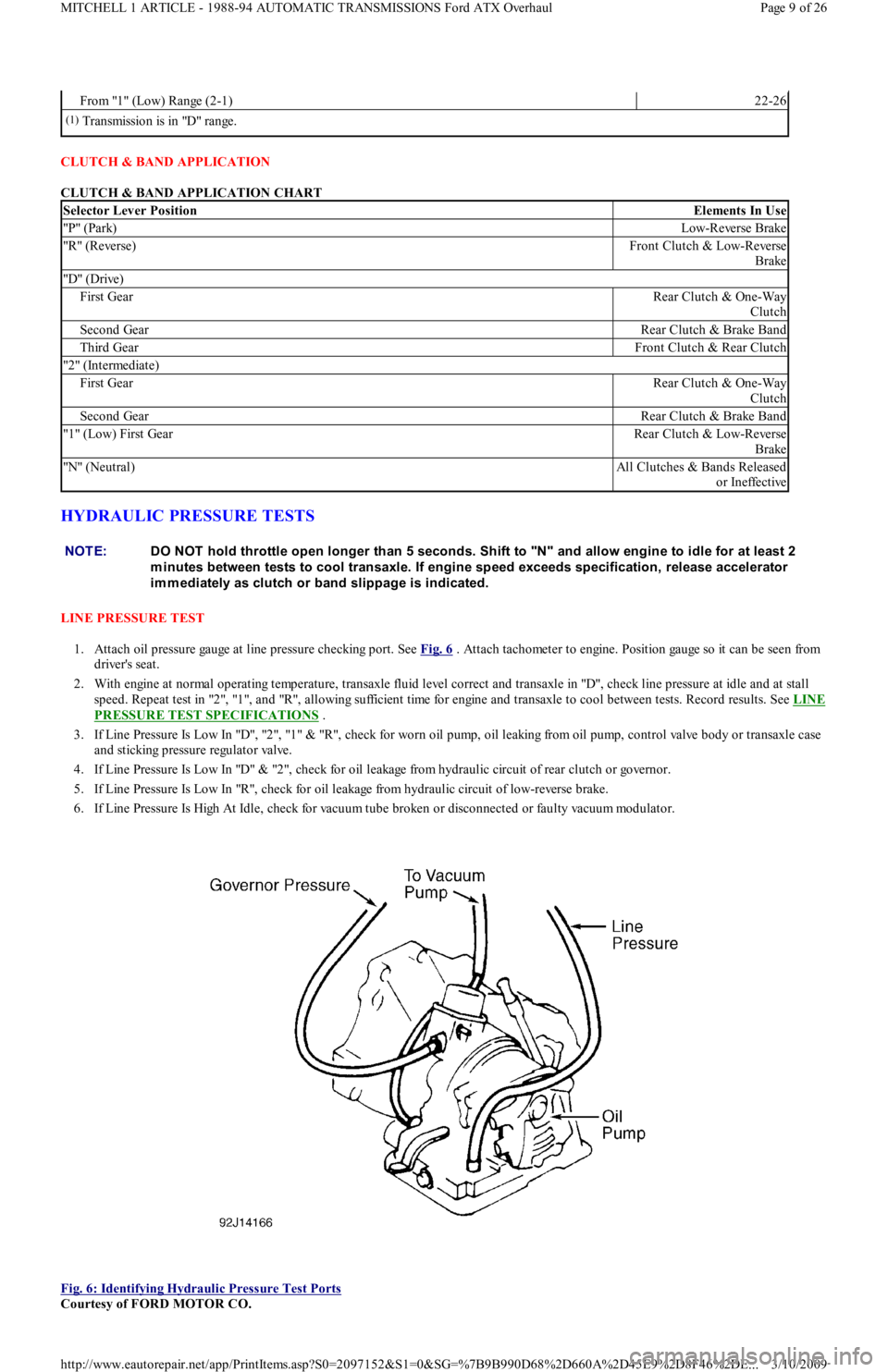
CLUTCH & BAND APPLICATION
CLUTCH & BAND APPLICATION CHART
HYDRAULIC PRESSURE TESTS
LINE PRESSURE TEST
1. Attach oil pressure gauge at line pressure checking port. See Fig. 6
. Attach tachometer to engine. Position gauge so it can be seen from
driver's seat.
2. With engine at normal operating temperature, transaxle fluid level correct and transaxle in "D", check line pressure at idle and at stall
sp eed . Rep eat t est in "2 ", "1 ", an d "R", al l o win g su fficien t t ime for engine and transaxle to cool between tests. Record results. See LINE
PRESSURE TEST SPECIFICATIONS .
3 . If Lin e Pressu re Is Lo w In "D", "2 ", "1 " & "R", ch eck fo r worn oil pump, oil leaking from oil pump, control valve body or transaxle case
and sticking pressure regulator valve.
4. If Line Pressure Is Low In "D" & "2", check for oil leakage from hydraulic circuit of rear clutch or governor.
5. If Line Pressure Is Low In "R", check for oil leakage from hydraulic circuit of low-reverse brake.
6. If Line Pressure Is High At Idle, check for vacuum tube broken or disconnected or faulty vacuum modulator.
Fig. 6: Identifying Hydraulic Pressure Test Ports
Courtesy of FORD MOTOR CO.
From "1" (Low) Range (2-1)22-26
(1)Transmission is in "D" range.
Selector Lever PositionElements In Use
"P" (Park)Low-Reverse Brake
"R" (Reverse)Front Clutch & Low-Reverse
Brake
"D" (Drive)
First GearRear Clutch & One-Way
Clutch
Second GearRear Clutch & Brake Band
Third GearFront Clutch & Rear Clutch
"2" (Intermediate)
First GearRear Clutch & One-Way
Clutch
Second GearRear Clutch & Brake Band
"1" (Low) First GearRear Clutch & Low-Reverse
Brake
"N" (Neutral)All Clutches & Bands Released
o r In effect ive
NOTE:DO NOT hold throttle open longer than 5 seconds. Shift to "N" and allow engine to idle for at least 2
m inutes between tests to cool transaxle. If engine speed exceeds specification, release accelerator
im m ediately as clutch or band slippage is indicated.
Page 9 of 26 MITCHELL 1 ARTICLE - 1988-94 AUTOMATIC TRANSMISSIONS Ford ATX Overhaul
3/10/2009 http://www.eautorepair.net/app/PrintItems.asp?S0=2097152&S1=0&SG=%7B9B990D68%2D660A%2D45E9%2D8F46%2DE
...
Page 418 of 454
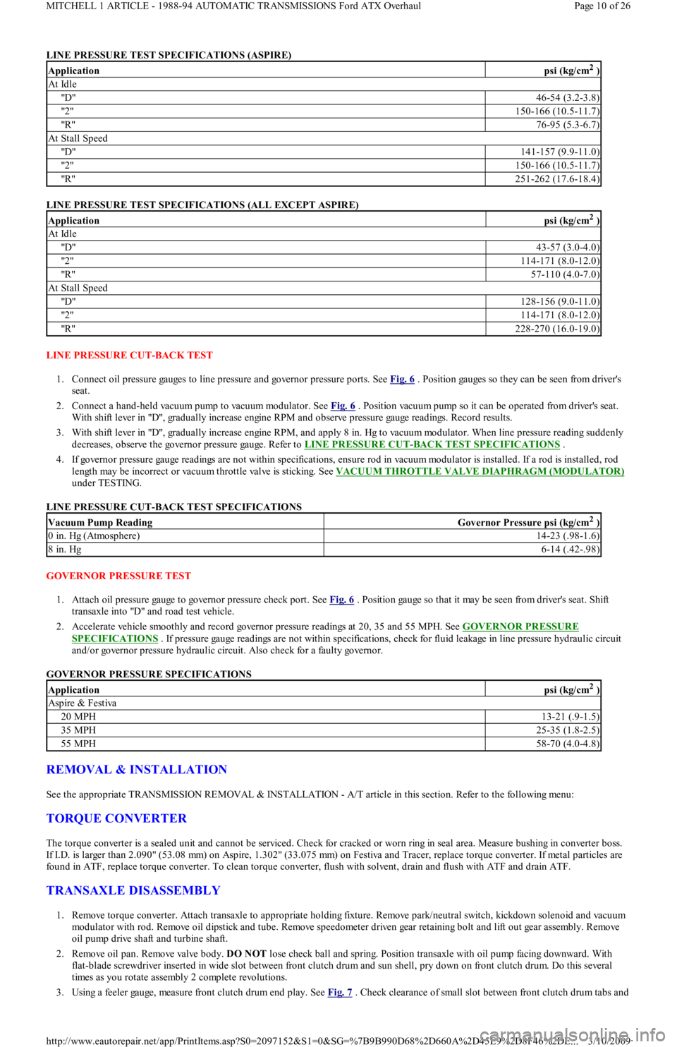
LINE PRESSURE TEST SPECIFICATIONS (ASPIRE)
LINE PRESSURE TEST SPECIFICATIONS (ALL EXCEPT ASPIRE)
LINE PRESSURE CUT-BACK TEST
1. Connect oil pressure gauges to line pressure and governor pressure ports. See Fig. 6
. Position gauges so they can be seen from driver's
seat.
2. Connect a hand-held vacuum pump to vacuum modulator. See Fig. 6
. Position vacuum pump so it can be operated from driver's seat.
With shift lever in "D", gradually increase engine RPM and observe pressure gauge readings. Record results.
3. With shift lever in "D", gradually increase engine RPM, and apply 8 in. Hg to vacuum modulator. When line pressure reading suddenly
decreases, observe the governor pressure gauge. Refer to LINE PRESSURE CUT
-BACK TEST SPECIFICATIONS .
4. If governor pressure gauge readings are not within specifications, ensure rod in vacuum modulator is installed. If a rod is installed, rod
length may be incorrect or vacuum throttle valve is sticking. See VACUUM THROTTLE VALVE DIAPHRAGM (MODULATOR)
under TESTING.
LINE PRESSURE CUT-BACK TEST SPECIFICATIONS
GOVERNOR PRESSURE TEST
1. Attach oil pressure gauge to governor pressure check port. See Fig. 6
. Position gauge so that it may be seen from driver's seat. Shift
transaxle into "D" and road test vehicle.
2. Accelerate vehicle smoothly and record governor pressure readings at 20, 35 and 55 MPH. See GOVERNOR PRESSURE
SPECIFICATIONS . If pressure gauge readings are not within specifications, check for fluid leakage in line pressure hydraulic circuit
and/or governor pressure hydraulic circuit. Also check for a faulty governor.
GOVERNOR PRESSURE SPECIFICATIONS
REMOVAL & INSTALLATION
See the appropriate TRANSMISSION REMOVAL & INSTALLATION - A/T article in this section. Refer to the following menu:
TORQUE CONVERTER
The torque converter is a sealed unit and cannot be serviced. Check for cracked or worn ring in seal area. Measure bushing in converter boss.
If I.D. is larger than 2.090" (53.08 mm) on Aspire, 1.302" (33.075 mm) on Festiva and Tracer, replace torque converter. If metal particles are
found in ATF, replace torque converter. To clean torque converter, flush with solvent, drain and flush with ATF and drain ATF.
TRANSAXLE DISASSEMBLY
1. Remove torque converter. Attach transaxle to appropriate holding fixture. Remove park/neutral switch, kickdown solenoid and vacuum
modulator with rod. Remove oil dipstick and tube. Remove speedometer driven gear retaining bolt and lift out gear assembly. Remove
oil pump drive shaft and turbine shaft.
2. Remove oil pan. Remove valve body. DO NOT lose check ball and spring. Position transaxle with oil pump facing downward. With
flat-blade screwdriver inserted in wide slot between front clutch drum and sun shell, pry down on front clutch drum. Do this seve r a l
times as you rotate assembly 2 complete revolutions.
3. Using a feeler gauge, measure front clutch drum end play. See Fig. 7
. Check clearance of small slot between front clutch drum tabs and
Applicationpsi (kg/cm2 )
At Idle
"D"46-54 (3.2-3.8)
"2 "150-166 (10.5-11.7)
"R"76-95 (5.3-6.7)
At Stall Speed
"D"141-157 (9.9-11.0)
"2 "150-166 (10.5-11.7)
"R"251-262 (17.6-18.4)
Applicationpsi (kg/cm2 )
At Idle
"D"43-57 (3.0-4.0)
"2 "114-171 (8.0-12.0)
"R"57-110 (4.0-7.0)
At Stall Speed
"D"128-156 (9.0-11.0)
"2 "114-171 (8.0-12.0)
"R"228-270 (16.0-19.0)
Vacuum Pump ReadingGovernor Pressure psi (kg/cm2 )
0 in. Hg (Atmosphere)14-23 (.98-1.6)
8 in. Hg6-14 (.42-.98)
Applicationpsi (kg/cm2 )
Aspire & Festiva
20 MPH13-21 (.9-1.5)
35 MPH25-35 (1.8-2.5)
55 MPH58-70 (4.0-4.8)
Page 10 of 26 MITCHELL 1 ARTICLE - 1988-94 AUTOMATIC TRANSMISSIONS Ford ATX Overhaul
3/10/2009 http://www.eautorepair.net/app/PrintItems.asp?S0=2097152&S1=0&SG=%7B9B990D68%2D660A%2D45E9%2D8F46%2DE
...
Page 428 of 454
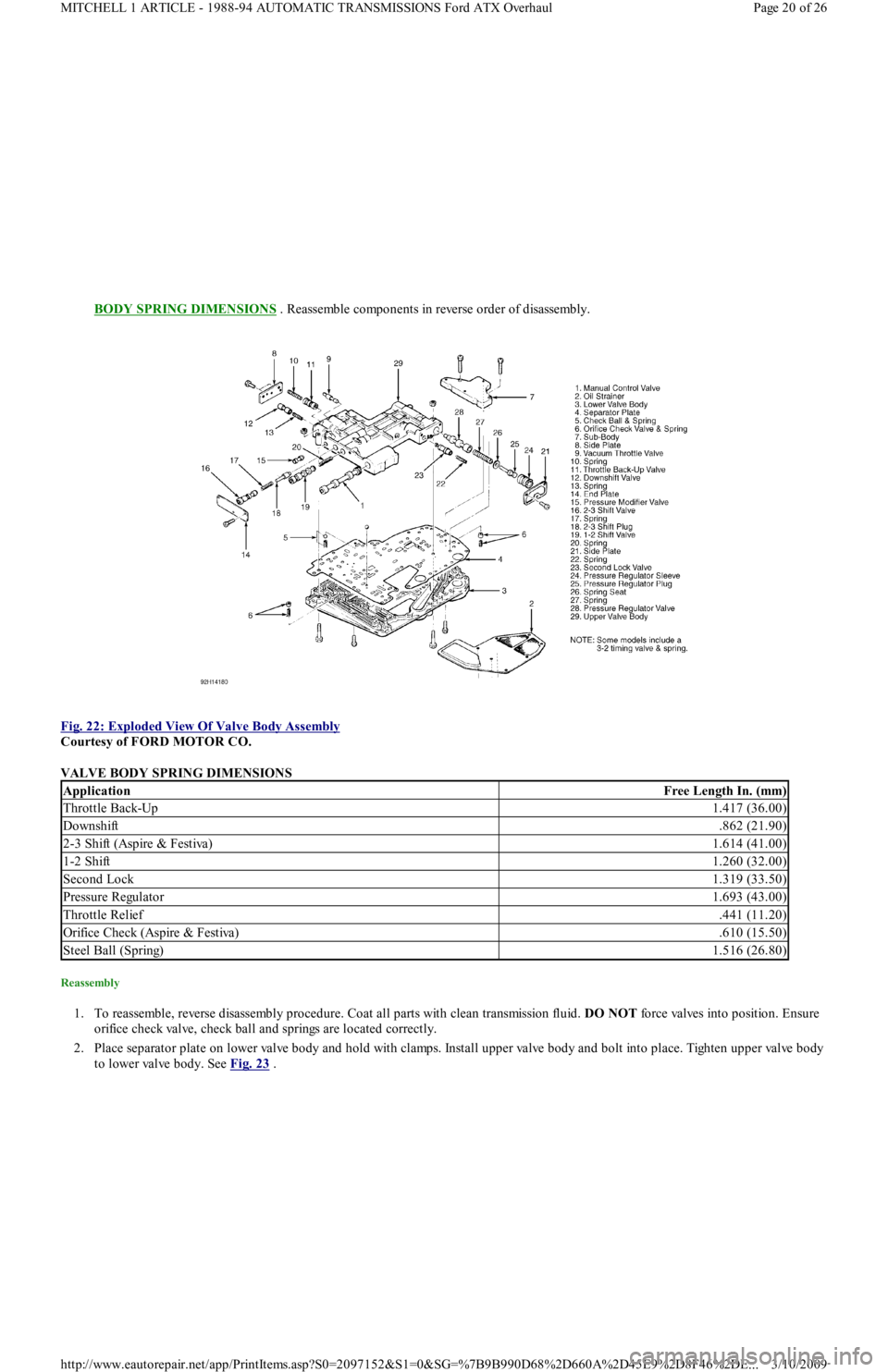
BODY SPRING DIMENSIONS . Reassemble components in reverse order of disassembly.
Fig. 22: Exploded View Of Valve Body Assembly
Courtesy of FORD MOTOR CO.
VALVE BODY SPRING DIMENSIONS
Reassembly
1. To reassemble, reverse disassembly procedure. Coat all parts with clean transmission fluid. DO NOT force valves into position. Ensure
orifice check valve, check ball and springs are located correctly.
2. Place separator plate on lower valve body and hold with clamps. Install upper valve body and bolt into place. Tighten upper valve body
to lower valve body. See Fig. 23
.
ApplicationFree Length In. (mm)
Throttle Back-Up1.417 (36.00)
Downshift.862 (21.90)
2-3 Shift (Aspire & Festiva)1.614 (41.00)
1-2 Shift1.260 (32.00)
Second Lock1.319 (33.50)
Pressure Regulator1.693 (43.00)
Throttle Relief.441 (11.20)
Orifice Check (Aspire & Festiva).610 (15.50)
Steel Ball (Spring)1.516 (26.80)
Page 20 of 26 MITCHELL 1 ARTICLE - 1988-94 AUTOMATIC TRANSMISSIONS Ford ATX Overhaul
3/10/2009 http://www.eautorepair.net/app/PrintItems.asp?S0=2097152&S1=0&SG=%7B9B990D68%2D660A%2D45E9%2D8F46%2DE
...
Page 429 of 454
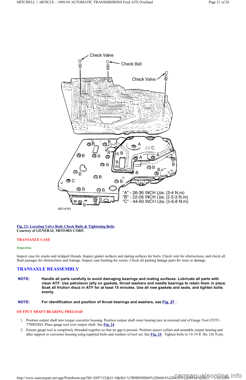
Fig. 23: Locating Valve Body Check Balls & Tightening Bolts
Courtesy of GENERAL MOTORS CORP.
TRANSAXLE CASE
Inspection
Inspect case for cracks and stripped threads. Inspect gasket surfaces and mating surfaces for burrs. Check vent for obstructions, and check all
fluid passages for obstructions and leakage. Inspect case bushing for scores. Check all parking linkage parts for wear or damage.
TRANSAXLE REASSEMBLY
OUTPUT SHAFT BEARING PRELOAD
1. Position output shaft into torque converter housing. Position output shaft outer bearing race in recessed end of Gauge Tool (T87C-
770002DJ). Place gauge tool over output shaft. See Fig. 24
.
2. Ensure gauge tool is completely threaded together so that no gap is present. Position spacer collars and assemble output bearing and
idler support to converter housing using supplied bolts and washers of tool set. See Fig. 24
. Tighten bolts to 14-19 ft. lbs. (26 N.m).
NOTE:Handle all parts carefully to avoid dam aging bearings and m ating surfaces. Lubricate all parts with
clean AT F. Use petroleum jelly on gaskets, thrust washers and needle bearings to retain them in place.
Soak all friction discs in AT F for at least 15 m inutes. Use all new gaskets and seals, and tighten bolts
evenly.
NOTE:For identification and position of thrust bearings and washers, see Fig. 27
.
Page 21 of 26 MITCHELL 1 ARTICLE - 1988-94 AUTOMATIC TRANSMISSIONS Ford ATX Overhaul
3/10/2009 http://www.eautorepair.net/app/PrintItems.asp?S0=2097152&S1=0&SG=%7B9B990D68%2D660A%2D45E9%2D8F46%2DE
...
Page 436 of 454
Back To Article
T RANSMISSION SERVICING - A/T
1988-93 T RANSMISSION SERVICING Ford Motor Co. Autom atic T ransm ission
IDENTIFICATION
AUTOMATIC TRANSMISSION APPLICATIONS
LUBRICATION
SERVICE INTERVALS
Check fluid level at every engine oil change. Fluid, filter changes and band adjustments are not required under normal operation. Under severe
service operating conditions, change fluid every 30 months or 30,000 miles. Adjust band when fluid is changed.
CHECKING FLUID LEVEL
With transmission at normal operating temperature, place vehicle on level surface. Apply parking brake and run engine at idle. Run gearshift
lever through all positions, ending in Park. With engine running, fluid level should be between "F" and "L" marks. DO NOT overfill.
RECOMMENDED FLUID
Use Dexron-II ATF.
FLUID CAPACITIES
TRANSMISSION REFILL CAPACITIES
DRAINING & REFILLING
1. Remove undercover and side cover to gain access to transaxle oil pan. Remove drain plug and drain fluid. Remove oil pan and discard
gasket. Clean or replace filter screen as necessary. Tighten screen bolts to 71-97 INCH lbs. (8-11 N.m).
2. Install oil pan bolts. Tighten bolts to 44-71 INCH lbs. (5-8 N.m). On all models, install drain plug with NEW washer. Tighten plug to
29-40 ft. lbs. (39-54 N.m).
3. Install undercover and side cover. Add about 3 qts. of specified ATF through dipstick guide tube. DO NOT overfill. Run engine to
normal operating temperature and check fluid level.
ADJUSTMENTS
NEUTRAL SAFETY SWITCH
Combination neutral safety and back-up light switch is screwed into transaxle case. No adjustments are necessary.
SHIFT CONTROL CABLE
1. Disconnect negative battery cable. Remove shift console. Place shift lever in Park. Remove shift lever knob and lock nut. Remove 4 shift
quadrant attaching screws.
2. Loosen shift cable adjuster nuts until they reach end of cable threads. See Fig. 1
. Place shift lever in Park. Tighten lower adjustment
nut until it lightly touches "T" joint, then tighten upper adjustment nut to 80-97 INCH lbs. (9-11 N.m).
3. Lightly press selector push rod and make sure guide pin clearance is correct. See Fig. 2
. Check guide pin clearance when shift lever is
in Neutral and Drive. Readjust shift cable as necessary.
4. Install 4 shift quadrant attaching screws, shift lever knob, lock nut and shift console. Connect negative battery cable.
ModelTransmission
FestivaATX/3HAT
NOTE:Capacities given are approxim ate refill am ounts that apply to overhaul situation. Correct fluid level
should be determ ined by m ark on dipstick.
ApplicationQts. (L)
ATX/3HAT5.6 (5.3)
CAUT ION: DO NOT use any type of gasket sealer or RT V on oil pan gasket. DO NOT overtighten.
CAUT ION: After com pleting linkage adjustm ents, be sure neutral safety switch operates properly. With parking
brake and service brakes applied, try to start engine in each gear position. Engine m ust crank only
when gearshift lever is in Neutral and Park.
Page 1 of 4 MITCHELL 1 ARTICLE - TRANSMISSION SERVICING - A/T 1988-93 TRANSMISSION SERVICING Ford Motor Co. Aut
...
3/10/2009 http://www.eautorepair.net/app/PrintItems.asp?S0=2097152&S1=0&SG=%7B9B990D68%2D660A%2D45E9%2D8F46%2DE
...
Page 441 of 454
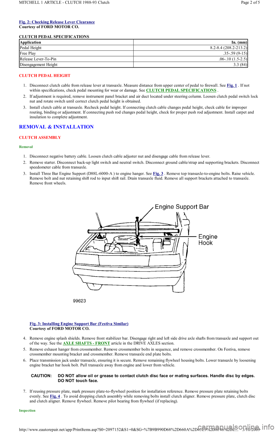
Fig. 2: Checking Release Lever Clearance
Courtesy of FORD MOTOR CO.
CLUTCH PEDAL SPECIFICATIONS
CLUTCH PEDAL HEIGHT
1. Disconnect clutch cable from release lever at transaxle. Measure distance from upper center of pedal to firewall. See Fig. 1
. If not
within specifications, check pedal mounting for wear or damage. See CLUTCH PEDAL SPECIFICATIONS
.
2. If adjustment is required, remove instrument panel bracket and air duct located under steering column. Loosen clutch pedal switch lock
nut and rotate switch until correct clutch pedal height is obtained.
3. Install clutch cable at transaxle. Recheck pedal height. If connecting clutch cable changes pedal height, check cable for improper
routing, binding or adjustment. If connecting push rod changes pedal height, check for proper push rod adjustment. Install carpet and
insulation to complete adjustment.
REMOVAL & INSTALLATION
CLUTCH ASSEMBLY
Removal
1. Disconnect negative battery cable. Loosen clutch cable adjuster nut and disengage cable from release lever.
2. Remove starter. Disconnect back-up light switch and neutral switch. Disconnect ground cable/strap and supporting brackets. Disconnect
speedometer cable from transaxle.
3. Install Three Bar Engine Support (D88L-6000-A ) to engine hanger. See Fig. 3
. Remove top transaxle-to-engine bolts. Raise vehicle.
Remove bolt and nut retaining shift rod to input shift rail. Drain transaxle fluid. Remove all support brackets attached to transaxle.
Remove front wheels.
Fig. 3: Installing Engine Support Bar (Festiva Similar)
Courtesy of FORD MOTOR CO.
4. Remove engine splash shields. Remove front stabilizer bar. Disengage right and left side drive axle shafts from transaxle and support out
of the way. See the AXLE SHAFTS
- FRONT article in the DRIVE AXLES section.
5. Remove exhaust hanger from crossmember. Remove crossmember bolts in sequence, and remove crossmember. On Festiva, remove
crossmember mounting bracket and crossmember. Remove transaxle end plate bolts.
6. Place transmission jack under transaxle, ensuring it is secure. Remove remaining flywheel housing bolts. Lower transaxle by loosening
engine bracket bar hook bolt. Pull transaxle away from engine and lower from vehicle.
7. If reusing pressure plate, mark pressure plate-to-flywheel position for installation reference. Remove pressure plate retaining bolts
evenly. See Fig. 4
. To avoid dropping clutch assembly while removing bolts install clutch aligner. Remove pressure plate, clutch disc
and clutch aligner. Remove flywheel. Remove pilot bearing from flywheel (if replacing).
Inspection
ApplicationIn. (mm)
Pedal Height8.2-8.4 (208.2-213.2)
Free Play.35-.59 (9-15)
Release Lever-To-Pin.06-.10 (1.5-2.5)
Disengagement Height3.3 (84)
CAUT ION: DO NOT allow oil or grease to contact clutch disc face or m ating surfaces. Handle disc by edges.
DO NOT touch face.
Page 2 of 5 MITCHELL 1 ARTICLE - CLUTCH 1988-93 Clutch
3/10/2009 http://www.eautorepair.net/app/PrintItems.asp?S0=2097152&S1=0&SG=%7B9B990D68%2D660A%2D45E9%2D8F46%2DE
...
Page 442 of 454
1. Check pressure plate surfaces for scoring, cracks or discoloration. Remove minor scratches or discoloration with fine emery cloth. Check
pressure plate diaphragm spring fingers for discoloration, scoring, broken or bent segments. Ensure all spring ends are the same height.
2. Check clutch disc lining surface for hardening or presence of oil. Check for worn clutch disc lining. Check for loose lining rivets.
Measure depth of rivet heads. Minimum allowable rivet depth is .012" (0.3 mm). Check for wear or rust on splines. Rust may be
removed with emery cloth.
3. Check flywheel surface for marks, scoring or discoloration. Minor surface repairs may be removed with fine emery cloth. Flywheel must
be machined if scoring, runout, or discoloration is excessive. Maximum flywheel runout is .008" (0.2 mm). Check for damaged or worn
ring gear teeth.
4. Check pilot bearing for wear. Check clutch release/throw out bearing for damage or wear at contact points. Rotate bearing in both
directions and check for binding or abnormal noise.
Installation
1. Replace release bearing and/or pilot bearing as necessary. Clean sealant from flywheel attaching bolt threads. Replace bolts if sealant
cannot be removed. Coat bolt threads with Stud/Bearing Mount Sealer (EOAZ-19554-B ), and install flywheel. Tighten bolts in a
diagonal sequence to specification. See TORQUE SPECIFICATIONS
at the end of this article.
2. Position clutch disc on flywheel with damper springs facing away from flywheel. Hold clutch disc in place with Clutch Aligner (T77F-
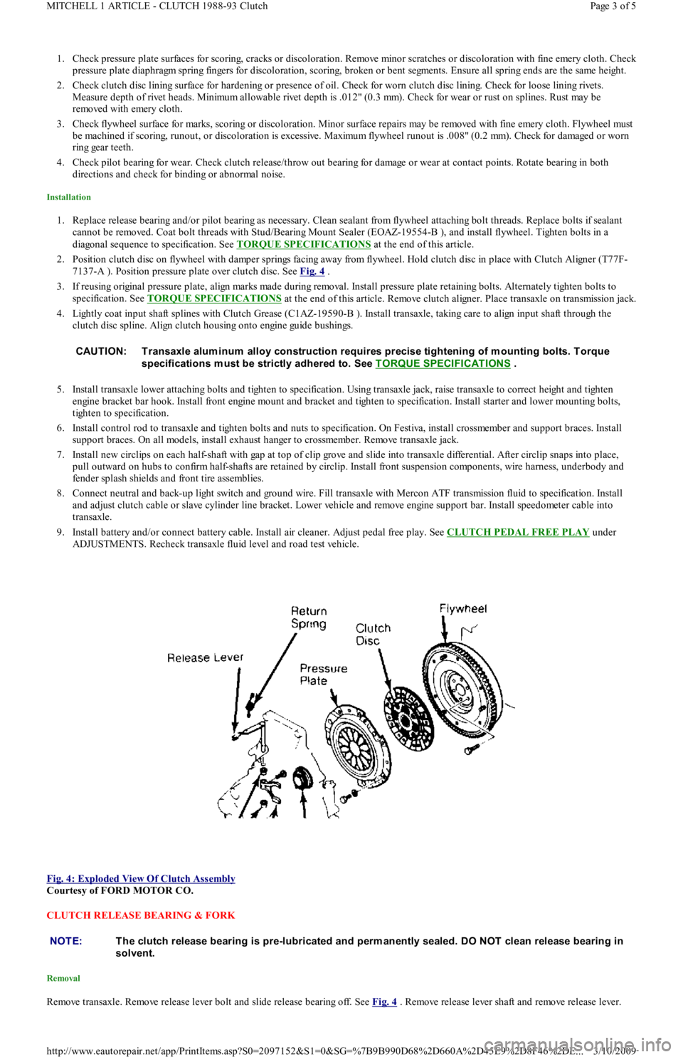
7137-A ). Position pressure plate over clutch disc. See Fig. 4
.
3. If reusing original pressure plate, align marks made during removal. Install pressure plate retaining bolts. Alternately tighten bolts to
specification. See TORQUE SPECIFICATIONS
at the end of this article. Remove clutch aligner. Place transaxle on transmission jack.
4. Lightly coat input shaft splines with Clutch Grease (C1AZ-19590-B ). Install transaxle, taking care to align input shaft through the
clutch disc spline. Align clutch housing onto engine guide bushings.
5. Install transaxle lower attaching bolts and tighten to specification. Using transaxle jack, raise transaxle to correct height and tighten
engine bracket bar hook. Install front engine mount and bracket and tighten to specification. Install starter and lower mounting b o l t s,
tighten to specification.
6. Install control rod to transaxle and tighten bolts and nuts to specification. On Festiva, install crossmember and support braces. Install
support braces. On all models, install exhaust hanger to crossmember. Remove transaxle jack.
7. Install new circlips on each half-shaft with gap at top of clip grove and slide into transaxle differential. After circlip snaps into place,
pull outward on hubs to confirm half-shafts are retained by circlip. Install front suspension components, wire harness, underbody and
fender splash shields and front tire assemblies.
8. Connect neutral and back-up light switch and ground wire. Fill transaxle with Mercon ATF transmission fluid to specification. In st al l
and adjust clutch cable or slave cylinder line bracket. Lower vehicle and remove engine support bar. Install speedometer cable into
transaxle.
9. Install battery and/or connect battery cable. Install air cleaner. Adjust pedal free play. See CLUTCH PEDAL FREE PLAY
under
ADJUSTMENTS. Recheck transaxle fluid level and road test vehicle.
Fig. 4: Exploded View Of Clutch Assembly
Courtesy of FORD MOTOR CO.
CLUTCH RELEASE BEARING & FORK
Removal
Remove transaxle. Remove release lever bolt and slide release bearing off. See Fig. 4 . Remove release lever shaft and remove release lever. CAUT ION: T ransaxle alum inum alloy construction requires precise tightening of m ounting bolts. T orque
specifications m ust be strictly adhered to. See T ORQUE SPECIFICAT IONS
.
NOTE:T he clutch release bearing is pre-lubricated and perm anently sealed. DO NOT clean release bearing in
solvent.
Page 3 of 5 MITCHELL 1 ARTICLE - CLUTCH 1988-93 Clutch
3/10/2009 http://www.eautorepair.net/app/PrintItems.asp?S0=2097152&S1=0&SG=%7B9B990D68%2D660A%2D45E9%2D8F46%2DE
...
Page 443 of 454
Inspection
Check release bearing rotation operation for roughness, sticking and noise. Check release lever and transaxle front bearing retainer for wear or
damage. Ensure bearing slides smoothly on transaxle input shaft. Check release lever shaft for bent, worn or damaged condition. Check all
mating surfaces for wear or damage. Replace worn or defective components.
Installation
Apply light film of grease to transmission front bearing retainer lever-to-bearing surfaces and release lever contact surface. Align bolt hole in
release lever and shaft. Apply Stud/Bearing Sealant (E0AZ-19554-B ) to release lever bolt. Fill grease groove in release bearing hub and
remove any excess grease. Install release lever return spring. To complete installation, reverse removal procedure.
PILOT BEARING
Removal & Installation
Remove transaxle, pressure plate, clutch disc and flywheel. Drive pilot bearing out of flywheel using a driver that makes full contact with
bearing outer race. Reverse procedure for installation.
CLUTCH CABLE
Removal & Installation
1. Disconnect clutch cable from release lever. Remove nuts retaining clutch cable at firewall. Unhook clutch cable at clutch pedal.
2. Remove clutch cable from engine compartment side. To install, apply lithium grease to pedal cable hook and joint between release lever
and pin. Reverse removal procedure to complete installation. See Fig. 2
.
OVERHAUL
TORQUE SPECIFICATIONS
TORQUE SPECIFICATIONS
TRANSAXLE FLUID LEVELS
TRANSAXLE FLUID LEVELS NOTE:DO NOT rem ove pilot bearing unless necessary.
NOTE:Manufacturer does not provide overhaul inform ation for clutch m aster cylinder and clutch release
cylinder.
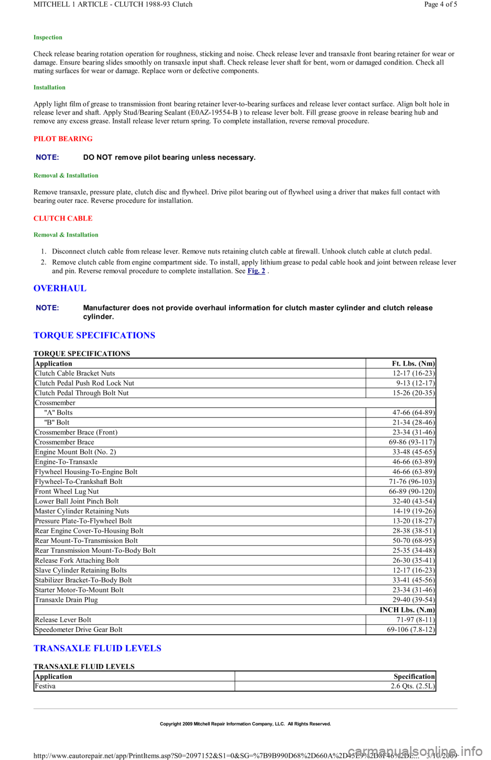
ApplicationFt. Lbs. (Nm)
Clutch Cable Bracket Nuts12-17 (16-23)
Clutch Pedal Push Rod Lock Nut9-13 (12-17)
Clutch Pedal Through Bolt Nut15-26 (20-35)
Crossmember
"A" Bo l t s47-66 (64-89)
"B" Bo l t21-34 (28-46)
Crossmember Brace (Front)23-34 (31-46)
Crossmember Brace69-86 (93-117)
Engine Mount Bolt (No. 2)33-48 (45-65)
Engine-To-Transaxle46-66 (63-89)
Flywheel Housing-To-Engine Bolt46-66 (63-89)
Flywheel-To-Crankshaft Bolt71-76 (96-103)
Front Wheel Lug Nut66-89 (90-120)
Lower Ball Joint Pinch Bolt32-40 (43-54)
Master Cylinder Retaining Nuts14-19 (19-26)
Pressure Plate-To-Flywheel Bolt13-20 (18-27)
Rear Engine Cover-To-Housing Bolt28-38 (38-51)
Rear Mount-To-Transmission Bolt50-70 (68-95)
Rear Transmission Mount-To-Body Bolt25-35 (34-48)
Release Fork Attaching Bolt26-30 (35-41)
Slave Cylinder Retaining Bolts12-17 (16-23)
Stabilizer Bracket-To-Body Bolt33-41 (45-56)
Starter Motor-To-Mount Bolt23-34 (31-46)
Transaxle Drain Plug29-40 (39-54)
INCH Lbs. (N.m)
Release Lever Bolt71-97 (8-11)
Speedometer Drive Gear Bolt69-106 (7.8-12)
ApplicationSpecification
Festiva2.6 Qts. (2.5L)
Copyr ight 2009 Mitchell Repair Information Company, LLC. All Rights Reserved.
Page 4 of 5 MITCHELL 1 ARTICLE - CLUTCH 1988-93 Clutch
3/10/2009 http://www.eautorepair.net/app/PrintItems.asp?S0=2097152&S1=0&SG=%7B9B990D68%2D660A%2D45E9%2D8F46%2DE
...