coolant temperature FORD FESTIVA 1991 Service Manual
[x] Cancel search | Manufacturer: FORD, Model Year: 1991, Model line: FESTIVA, Model: FORD FESTIVA 1991Pages: 454, PDF Size: 9.53 MB
Page 6 of 454
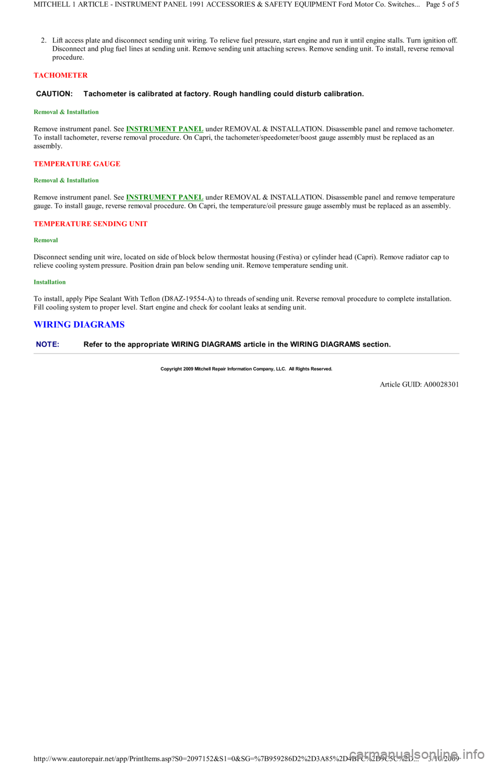
2. Lift access plate and disconnect sending unit wiring. To relieve fuel pressure, start engine and run it until engine stalls. Turn ignition off.
Disconnect and plug fuel lines at sending unit. Remove sending u n it a t t a c h in g sc r e ws. R e mo ve se n d in g u n it . To in st a l l , r e ve r se removal
procedure.
TACHOMETER
Removal & Installation
Remo ve in st ru men t p an el . See INSTRUMENT PANEL under REMOVAL & INSTALLATION. Disassemble panel and remove tachometer.
To install tachometer, reverse removal procedure. On Capri, the tachometer/speedometer/boost gauge assembly must be replaced as an
assembly.
TEMPERATURE GAUGE
Removal & Installation
Remo ve in st ru men t p an el . See INSTRUMENT PANEL under REMOVAL & INSTALLATION. Disassemble panel and remove temperature
gauge. To install gauge, reverse removal procedure. On Capri, the temperature/oil pressure gauge assembly must be replaced as an assembly.
TEMPERATURE SENDING UNIT
Removal
Disconnect sending unit wire, located on side of block below thermostat housing (Festiva) or cylinder head (Capri). Remove radiator cap to
relieve cooling system pressure. Position drain pan below sending unit. Remove temperature sending unit.
Installation
To install, apply Pipe Sealant With Teflon (D8AZ-19554-A) to threads of sending unit. Reverse removal procedure to complete installation.
Fill cooling system to proper level. Start engine and check for coolant leaks at sending unit.
WIRING DIAGRAMS
CAUT ION: T achom eter is calibrated at factory. Rough handling could disturb calibration.
NOTE:Refer to the appropriate WIRING DIAGRAMS article in the WIRING DIAGRAMS section.
Copyr ight 2009 Mitchell Repair Information Company, LLC. All Rights Reserved.
Article GUID: A00028301
Page 5 of 5 MITCHELL 1 ARTICLE - INSTRUMENT PANEL 1991 ACCESSORIES & SAFETY EQUIPMENT Ford Motor Co. Switches
...
3/10/2009 http://www.eautorepair.net/app/PrintItems.asp?S0=2097152&S1=0&SG=%7B959286D2%2D3A85%2D4BFC%2D9C5C%2D
...
Page 46 of 454
Back To Article
ELECT RICAL COMPONENT LOCAT OR
1991-92 ELECT RICAL COMPONENT LOCAT ION Ford Motor Co. Electrical Com ponents
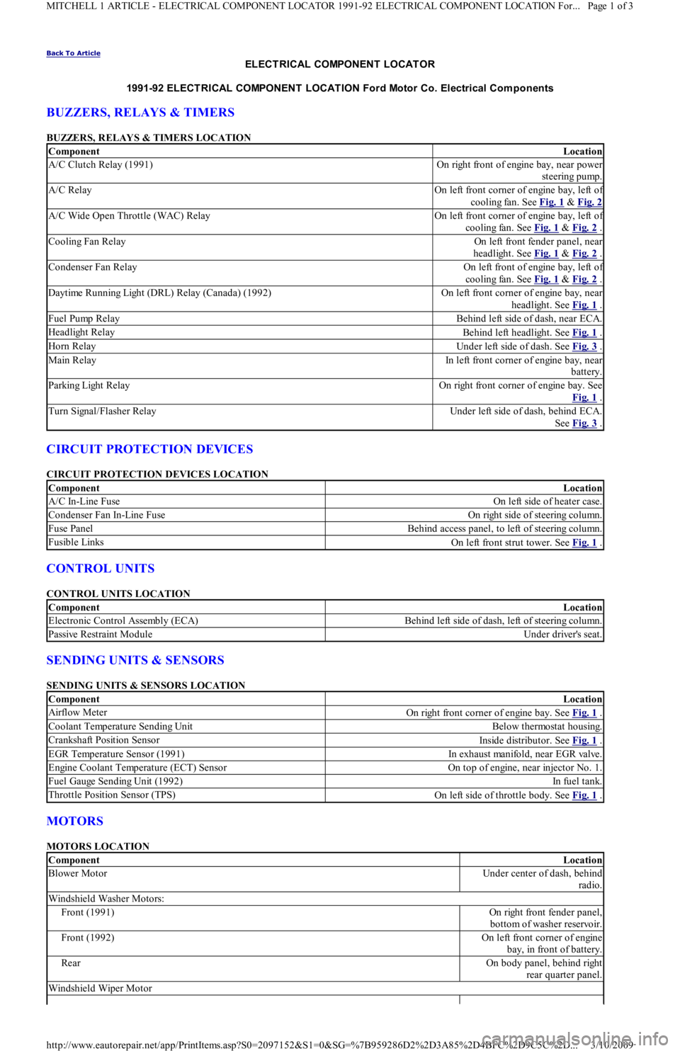
BUZZERS, RELAYS & TIMERS
BUZZERS, RELAYS & TIMERS LOCATION
CIRCUIT PROTECTION DEVICES
CIRCUIT PROTECTION DEVICES LOCATION
CONTROL UNITS
CONTROL UNITS LOCATION
SENDING UNITS & SENSORS
SENDING UNITS & SENSORS LOCATION
MOTORS
MOTORS LOCATION
ComponentLocation
A/C Clutch Relay (1991)On right front of engine bay, near power
steering pump.
A/C RelayOn left front corner of engine bay, left of
cooling fan. See Fig. 1
& Fig. 2
A/C Wide Open Throttle (WAC) RelayOn left front corner of engine bay, left of
cooling fan. See Fig. 1
& Fig. 2 .
Cooling Fan RelayOn left front fender panel, near
headlight. See Fig. 1
& Fig. 2 .
Condenser Fan RelayOn left front of engine bay, left of
cooling fan. See Fig. 1
& Fig. 2 .
Daytime Running Light (DRL) Relay (Canada) (1992)On left front corner of engine bay, near
headlight. See Fig. 1
.
Fuel Pump RelayBehind left side of dash, near ECA.
Headlight RelayBehind left headlight. See Fig. 1 .
Horn RelayUnder left side of dash. See Fig. 3 .
Main RelayIn left front corner of engine bay, near
battery.
P a r kin g Ligh t R e l a yOn right front corner of engine bay. See
Fig. 1
.
Turn Signal/Flasher RelayUnder left side of dash, behind ECA.
See Fig. 3
.
ComponentLocation
A/C In-Line FuseOn left side of heater case.
Condenser Fan In-Line FuseOn right side of steering column.
Fuse PanelBehind access panel, to left of steering column.
Fusible LinksOn left front strut tower. See Fig. 1 .
ComponentLocation
Electronic Control Assembly (ECA)Behind left side of dash, left of steering column.
Passive Restraint ModuleUnder driver's seat.
ComponentLocation
Airflow MeterOn right front corner of engine bay. See Fig. 1 .
Coolant Temperature Sending UnitBelow thermostat housing.
Crankshaft Position SensorInside distributor. See Fig. 1 .
EGR Temperature Sensor (1991)In exhaust manifold, near EGR valve.
Engine Coolant Temperature (ECT) SensorOn top of engine, near injector No. 1.
Fuel Gauge Sending Unit (1992)In fu el t an k.
Throttle Position Sensor (TPS)On left side of throttle body. See Fig. 1 .
ComponentLocation
Blower MotorUnder center of dash, behind
radio.
Windshield Washer Motors:
Front (1991)On right front fender panel,
bottom of washer reservoir.
Front (1992)On left front corner of engine
bay, in front of battery.
RearOn body panel, behind right
rear quarter panel.
Windshield Wiper Motor
Page 1 of 3 MITCHELL 1 ARTICLE - ELECTRICAL COMPONENT LOCATOR 1991-92 ELECTRICAL COMPONENT LOCATION For...
3/10/2009 http://www.eautorepair.net/app/PrintItems.asp?S0=2097152&S1=0&SG=%7B959286D2%2D3A85%2D4BFC%2D9C5C%2D
...
Page 66 of 454
Autolamp Control RelayHeadlight Systems; Daytime Running Lights
Automatic Shutdown (ASD) RelayEngine Performance; Generators & Regulators
Autostick SwitchEngine Performance
Auxiliary Battery RelayGenerators & Regulators
Back-Up LightsBack-Up Lights; Exterior Lights
Barometric (BARO) Pressure SensorEngine Performance
BatteryPower Distribution
Battery Temperature SensorEngine Performance
Body Control ModuleBody Control Computer; Anti-Theft System; Daytime Running
Lights; Engine Performance; Headlight Systems; Warning Systems
Boost Control SolenoidEngine Performance
Boost SensorEngine Performance
Brake Fluid Level SwitchAnalog Instrument Panels
Brake On/Off (BOO) SwitchCruise Control Systems; Engine Performance; Shift Interlock
Systems
Buzzer ModuleWarning Systems
Camshaft Position (CMP) SensorEngine Performance
Central Control ModuleAnti-Theft System
ClockspringAir Bag Restraint System; Cruise Control Systems; Steering
Column Switches
Clutch Pedal Position SwitchStarters
Clutch Start SwitchStarters
Combination MeterAnalog Instrument Panels
Constant Control Relay Module (CCRM)Engine Performance; Electric Cooling Fans
Convenience CenterPower Distribution; Illumination/Interior Lights
Convertible Top MotorPower Convertible Top
Convertible Top SwitchPower Convertible Top
Crankshaft Position (CKP) SensorEngine Performance
Cruise Control ModuleCruise Control Systems
Cruise Control SwitchCruise Control Systems
Condenser Fan Relay(s)Electric Cooling Fans
Data Link Connector (DLC)Engine Performance
Da yt ime R u n n in g Ligh t s M o d u l eDaytime Running Lights; Exterior Lights
Defogger RelayRear Window Defogger
Diagnostic Energy Reserve Module (DERM)Air Bag Restraint System
Discriminating Sensor (Air Bag)Air Bag Restraint System
DistributorEngine Performance
Door Lock ActuatorsPower Door Locks; Remote Keyless Entry
Door Lock Relay(s)Power Door Locks
Electrochromic MirrorPower Mirrors
Electronic Level Control (ELC) Height SensorElectronic Suspension
Electronic Level Control (ELC) ModuleElectronic Suspension
Engine Coolant Temperature (ECT) Sending UnitAnalog Instrument Panels
Engine Coolant Temperature (ECT) SensorEngine Performance
Engine Control ModuleEngine Performance; Generators & Regulators; Starters
ETACS ECUWarning Systems; Power Windows; Remote Keyless Entry
Evaporative (EVAP) Emissions CanisterEngine Performance
EVAP Canister Purge SolenoidEngine Performance
EVAP Canister Vent SolenoidEngine Performance
Exhaust Gas Recirculation (EGR) ValveEngine Performance
Fuel Tank Vacuum SensorEngine Performance
F o g Ligh t sHeadlight Systems; Daytime Running Lights
F o g Ligh t R e l a yHeadlight Systems; Daytime Running Lights
Fuel Door Release SolenoidPower Fuel Door Release
Fuel Gauge Sending UnitAnalog Instrument Panels
Fuel InjectorsEngine Performance
Fuel PumpEngine Performance
Fuel Pump RelayEngine Performance; Power Distribution
Fuse/Relay BlockPower Distribution
Fusible LinksPower Distribution; Generators & Regulators; Starters
GeneratorGenerators & Regulators; Engine Performance; Power Distribution
Generic Electronic Module (GEM)Body Control Modules; Electronic Suspension
Glow Plug RelayEngine Performance
Glow PlugsEngine Performance
GroundsGround Distribution
Headlight Door ModuleHeadlight Doors
Headlight RelayHeadlight Systems; Daytime Running Lights
HeadlightsHeadlight Systems; Daytime Running Lights
Heated Oxygen Sensor(s) (HO2S)Engine Performance
Heated Windshield Control ModuleHeated Windshields
Page 4 of 6 MITCHELL 1 ARTICLE - GENERAL INFORMATION Using Mitchell1's Wiring Diagrams
3/10/2009 http://www.eautorepair.net/app/PrintItems.asp?S0=2097152&S1=0&SG=%7B959286D2%2D3A85%2D4BFC%2D9C5C%2D
...
Page 86 of 454
Back To Article
ENGINE COOLING FAN
1990-92 ENGINE COOLING Ford Motor Co. Engine Cooling Fans
DESCRIPTION
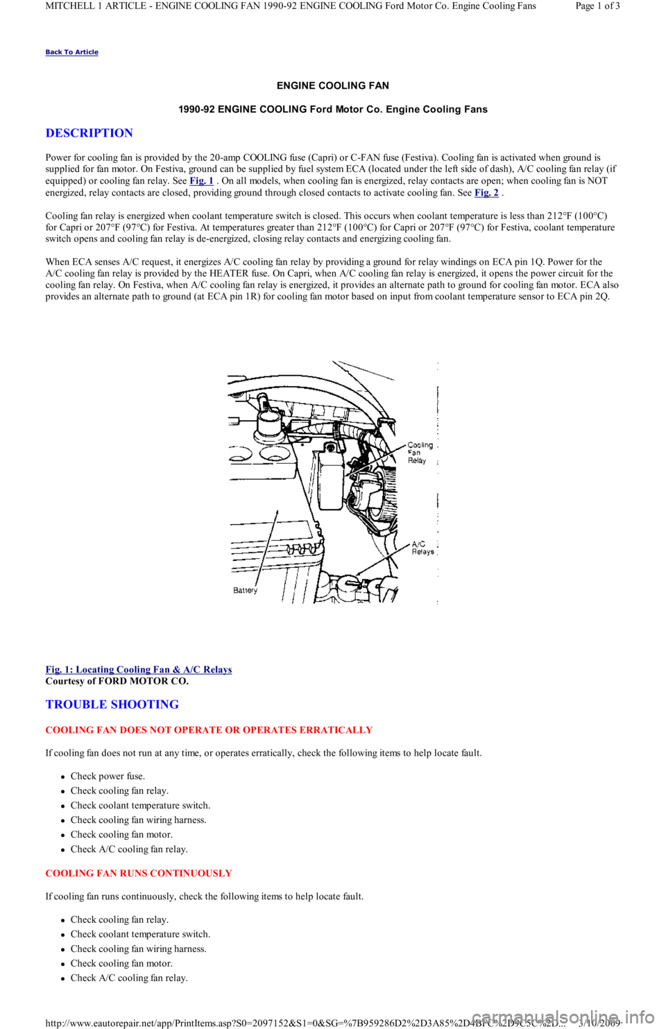
Power for cooling fan is provided by the 20-amp COOLING fuse (Capri) or C-FAN fuse (Festiva). Cooling fan is activated when ground is
supplied for fan motor. On Festiva, ground can be supplied by fuel system ECA (located under the left side of dash), A/C cooling fan relay (if
equipped) or cooling fan relay. See Fig. 1
. On all models, when cooling fan is energized, relay contacts are open; when cooling fan is NOT
energized, relay contacts are closed, providing ground through closed contacts to activate cooling fan. See Fig. 2
.
Cooling fan relay is energized when coolant temperature switch is closed. This occurs when coolant temperature is less than 212°F (1 00 °C)
for Capri or 207°F (97°C) for Festiva. At temperatures greater than 212°F (100°C) for Capri or 207°F (97°C) for Festiva, coolant temperature
switch opens and cooling fan relay is de-energized, closing relay contacts and energizing cooling fan.
When ECA senses A/C request, it energizes A/C cooling fan relay by providing a ground for relay windings on ECA pin 1Q. Power for the
A/C cooling fan relay is provided by the HEATER fuse. On Capri, when A/C cooling fan relay is energized, it opens the power circuit for the
cooling fan relay. On Festiva, when A/C cooling fan relay is energized, it provides an alternate path to ground for cooling fan mo t o r. E CA al so
provides an alternate path to ground (at ECA pin 1R) for cooling fan motor based on input from coolant temperature sensor to ECA pin 2Q.
Fig. 1: Locating Cooling Fan & A/C Relays
Courtesy of FORD MOTOR CO.
TROUBLE SHOOTING
COOLING FAN DOES NOT OPERATE OR OPERATES ERRATICALLY
If cooling fan does not run at any time, or operates erratically, check the following items to help locate fault.
Check power fuse.
Check cooling fan relay.
Check coolant temperature switch.
Check cooling fan wiring harness.
Check cooling fan motor.
Check A/C cooling fan relay.
COOLING FAN RUNS CONTINUOUSLY
If cooling fan runs continuously, check the following items to help locate fault.
Check cooling fan relay.
Check coolant temperature switch.
Check cooling fan wiring harness.
Check cooling fan motor.
Check A/C cooling fan relay.
Page 1 of 3 MITCHELL 1 ARTICLE - ENGINE COOLING FAN 1990-92 ENGINE COOLING Ford Motor Co. Engine Cooling Fans
3/10/2009 http://www.eautorepair.net/app/PrintItems.asp?S0=2097152&S1=0&SG=%7B959286D2%2D3A85%2D4BFC%2D9C5C%2D
...
Page 87 of 454
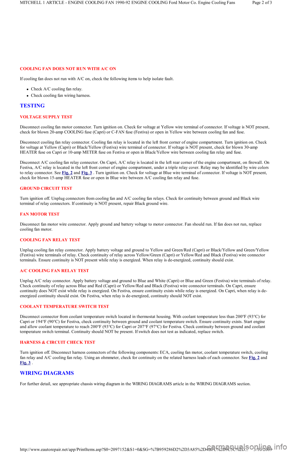
COOLING FAN DOES NOT RUN WITH A/C ON
If cooling fan does not run with A/C on, check the following items to help isolate fault.
Check A/C cooling fan relay.
Check cooling fan wiring harness.
TESTING
VOLTAGE SUPPLY TEST
Disconnect cooling fan motor connector. Turn ignition on. Check for voltage at Yellow wire terminal of connector. If voltage is NOT present,
check for blown 20-amp COOLING fuse (Capri) or C-FAN fuse (Festiva) or open in Yellow wire between cooling fan and fuse.
Disconnect cooling fan relay connector. Cooling fan relay is located in the left front corner of engine compartment. Turn ignition on. Check
for voltage at Yellow (Capri) or Black/Yellow (Festiva) wire terminal of connector. If voltage is NOT present, check for blown 30-amp
HEATER fuse on Capri or 10-amp METER fuse on Festiva or open in Black/Yellow wire between cooling fan relay and fuse.
Disconnect A/C cooling fan relay connector. On Capri, A/C relay is located in the left rear corner of the engine compartment, on firewall. On
Festiva, A/C relay is located in the left front corner of engine compartment, under a triple relay cover. Relay may be identified by wire colors
to relay connector. See Fig. 2
and Fig. 3 . Turn ignition on. Check for voltage at Blue wire terminal of connector. If voltage is NOT present,
check for blown 15-amp HEATER fuse or open in Blue wire between A/C cooling fan relay and fuse.
GROUND CIRCUIT TEST
Turn ignition off. Unplug connectors from cooling fan and A/C cooling fan relays. Check for continuity between ground and Black wire
terminal of relay connectors. If continuity is NOT present, repair Black ground wire.
FAN MOTOR TEST
Disconnect fan motor wire connector. Apply ground and battery voltage to motor connector. Fan should run. If fan does not run, replace
cooling fan motor.
COOLING FAN RELAY TEST
Unplug cooling fan relay connector. Apply battery voltage and ground to Yellow and Green/Red (Capri) or Black/Yellow and Green/Yellow
(Festiva) wire terminals of relay. Check continuity of relay across Yellow/Green (Capri) or Yellow/Red and Black (Festiva) wire connector
terminals. Ensure continuity is NOT present while relay is energized. When relay is de-energized, continuity should exist.
A/C COOLING FAN RELAY TEST
Unplug A/C relay connector. Apply battery voltage and ground to Blue and White (Capri) or Blue and Green (Festiva) wire terminals of relay.
Check continuity of relay across Blue and Red (Capri) or Yellow/Red and Black (Festiva) wire connector terminals. On Capri, ensure
continuity does NOT exist while relay is energized. On Festiva, ensure continuity exists while relay is energized. On Capri, when relay is de-
energized continuity should exist. On Festiva, when relay is de-energized, continuity should NOT exist.
COOLANT TEMPERATURE SWITCH TEST
Disconnect connector from coolant temperature switch located in thermostat housing. With coolant temperature less than 200°F (93°C) for
Capri or 194°F (90°C) for Festiva, check continuity between ground and coolant temperature switch. Ensure continuity exists. Start engine
and allow coolant temperature to reach 200°F (93°C) for Capri or 207°F (97°C) for Festiva. Check continuity between ground and coolant
temperature switch terminal. Continuity should NOT be present. If switch does not test as indicated, replace switch.
HARNESS & CIRCUIT CHECK TEST
Turn ignition off. Disconnect harness connectors of the following components: ECA, cooling fan motor, coolant temperature switch, cooling
fan relay and A/C cooling fan relay. Using an ohmmeter, check for continuity on the related harness leads of each connector. See Fig. 2
and
Fig. 3
.
WIRING DIAGRAMS
For further detail, see appropriate chassis wiring diagram in the WIRING DIAGRAMS article in the WIRING DIAGRAMS section.
Page 2 of 3 MITCHELL 1 ARTICLE - ENGINE COOLING FAN 1990-92 ENGINE COOLING Ford Motor Co. Engine Cooling Fans
3/10/2009 http://www.eautorepair.net/app/PrintItems.asp?S0=2097152&S1=0&SG=%7B959286D2%2D3A85%2D4BFC%2D9C5C%2D
...
Page 150 of 454
Back To Article
K - SENSOR RANGE CHART S
1991 ENGINE PERFORMANCE Ford Motor Co. Sensor Operating Range Charts
INTRODUCTION
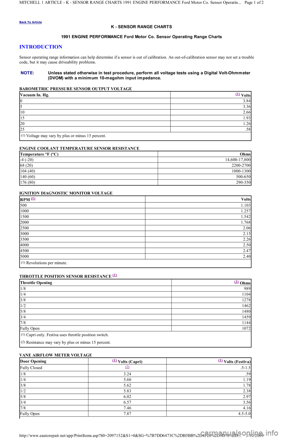
Sensor operating range information can help determine if a sensor is out of calibration. An out-of-calibration sensor may not set a trouble
code, but it may cause driveability problems.
BAROMETRIC PRESSURE SENSOR OUTPUT VOLTAGE
ENGINE COOLANT TEMPERATURE SENSOR RESISTANCE
IGNITION DIAGNOSTIC MONITOR VOLTAGE
THROTTLE POSITION SENSOR RESISTANCE
(1)
VANE AIRFLOW METER VOLTAGE NOTE:Unless stated otherwise in test procedure, perform all voltage tests using a Digital Volt-Ohm m eter
(DVOM) with a m inim um 10-m egohm input im pedance.
Vacuum In. Hg.(1) Volts
03.84
53.36
102.66
151.93
201.26
25.58
(1)Voltage may vary by plus or minus 15 percent.
Temperature °F (°C)Ohms
-4 (-20)14,600-17,800
68 (20)2200-2700
104 (40)1000-1300
140 (60)500-650
176 (80)290-350
RPM (1) Volts
5001.103
10001.257
15001.542
20001.768
25002.06
30002.15
35002.26
40002.50
45002.47
50002.40
(1)Revolutions per minute.
Throttle Opening(2) Ohms
1/8989
1/41104
3/81278
1/21462
5/81480
3/41459
7/81144
Fully Open1072
(1)Capri only. Festiva uses throttle position switch.
(2)Resistance may vary by plus or minus 15 percent.
Door Opening(1) Volts (Capri)(1) Volts (Festiva)
Fully Closed(2) .5-1.5
1/83.24.59
1/45.601.19
3/85.621.78
1/25.832.38
5/86.022.97
3/46.573.56
7/87.464.16
Fully Open7.874.5-5.0
Page 1 of 2 MITCHELL 1 ARTICLE - K - SENSOR RANGE CHARTS 1991 ENGINE PERFORMANCE Ford Motor Co. Sensor Operatin
...
3/10/2009 http://www.eautorepair.net/app/PrintItems.asp?S0=2097152&S1=0&SG=%7B7DD6473C%2DB5BB%2D4F20%2D9D70%2D
...
Page 153 of 454
Back To Article
C - SPECIFICATIONS
1991 ENGINE PERFORMANCE Ford/Mercury - Service & Adjustm ent Specifications
INTRODUCTION
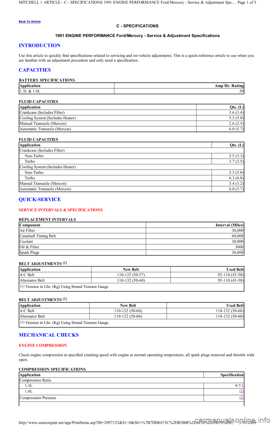
Use this article to quickly find specifications related to servicing and on-vehicle adjustments. This is a quick-reference article to use when you
are familiar with an adjustment procedure and only need a specification.
CAPACITIES
BATTERY SPECIFICATIONS
FLUID CAPACITIES
FLUID CAPACITIES
QUICK-SERVICE
SERVICE INTERVALS & SPECIFICATIONS
REPLACEMENT INTERVALS
BELT ADJUSTMENTS
(1)
BELT ADJUSTMENTS
(1)
MECHANICAL CHECKS
ENGINE COMPRESSION
Check engine compression at specified cranking speed with engine at normal operating temperature, all spark plugs removed and throttle wide
open.
COMPRESSION SPECIFICATIONS
ApplicationAmp Hr. Rating
1.3L & 1.6L50
ApplicationQts. (L)
Crankcase (Includes Filter)3.6 (3.4)
Cooling System (Includes Heater)5.3 (5.0)
Manual Transaxle (Mercon)2.6 (2.5)
Automatic Transaxle (Mercon)6.0 (5.7)
ApplicationQts. (L)
Crankcase (Includes Filter)
Non-Turbo3.5 (3.3)
Turbo3.7 (3.5)
Cooling System (Includes Heater)
Non-Turbo5.3 (5.0)
Turbo6.3 (6.0)
Manual Transaxle (Mercon)3.4 (3.2)
Automatic Transaxle (Mercon)6.0 (5.7)
ComponentInterval (Miles)
Air Filter30,000
Camsh aft Timin g Bel t60,000
Coolant30,000
Oil & Filter3000
Spark Plugs30,000
ApplicationNew BeltUsed Belt
A/C Belt110-125 (50-57)92-110 (42-50)
Alternator Belt110-132 (50-60)95-110 (43-50)
(1)Tension in Lbs. (Kg) Using Strand Tension Gauge
ApplicationNew BeltUsed Belt
A/C Belt110-132 (50-60)110-132 (50-60)
Alternator Belt110-132 (50-60)110-132 (50-60)
(1)Tension in Lbs. (Kg) Using Strand Tension Gauge.
ApplicationSpecification
Compression Ratio
1.3L9.7:1
1.6L(1)
Compression Pressure(2)
Page 1 of 3 MITCHELL 1 ARTICLE - C - SPECIFICATIONS 1991 ENGINE PERFORMANCE Ford/Mercury - Service & Adjustment Spe
...
3/10/2009 http://www.eautorepair.net/app/PrintItems.asp?S0=2097152&S1=0&SG=%7B7DD6473C%2DB5BB%2D4F20%2D9D70%2D
...
Page 162 of 454
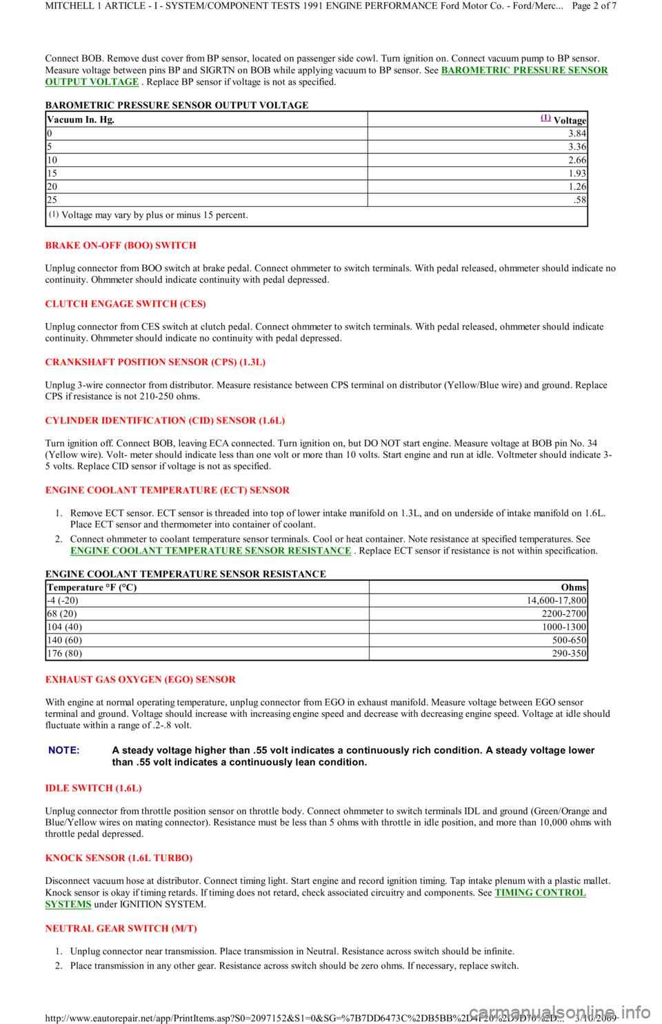
Connect BOB. Remove dust cover from BP sensor, located on passenger side cowl. Turn ignition on. Connect vacuum pump to BP sensor.
Measure voltage between pins BP and SIGRTN on BOB while applying vacuum to BP sensor. See BAROMETRIC PRESSURE SENSOR
OUTPUT VOLTAGE . Replace BP sensor if voltage is not as specified.
BAROMETRIC PRESSURE SENSOR OUTPUT VOLTAGE
BRAKE ON-OFF (BOO) SWITCH
Unplug connector from BOO switch at brake pedal. Connect ohmmeter to switch terminals. With pedal released, ohmmeter should indicate no
continuity. Ohmmeter should indicate continuity with pedal depressed.
CLUTCH ENGAGE SWITCH (CES)
Unplug connector from CES switch at clutch pedal. Connect ohmmeter to switch terminals. With pedal released, ohmmeter should indicate
continuity. Ohmmeter should indicate no continuity with pedal depressed.
CRANKSHAFT POSITION SENSOR (CPS) (1.3L)
Unplug 3-wire connector from distributor. Measure resistance between CPS terminal on distributor (Yellow/Blue wire) and ground. Replace
CPS if resistance is not 210-250 ohms.
CYLINDER IDENTIFICATION (CID) SENSOR (1.6L)
Turn ignition off. Connect BOB, leaving ECA connected. Turn ignition on, but DO NOT start engine. Measure voltage at BOB pin No. 34
(Yellow wire). Volt- meter should indicate less than one volt or more than 10 volts. Start engine and run at idle. Voltmeter should indicate 3-
5 volts. Replace CID sensor if voltage is not as specified.
ENGINE COOLANT TEMPERATURE (ECT) SENSOR
1. Remove ECT sensor. ECT sensor is threaded into top of lower intake manifold on 1.3L, and on underside of intake manifold on 1.6L.
Place ECT sensor and thermometer into container of coolant.
2. Connect ohmmeter to coolant temperature sensor terminals. Cool or heat container. Note resistance at specified temperatures. See
ENGINE COOLANT TEMPERATURE SENSOR RESISTANCE
. Replace ECT sensor if resistance is not within specification.
ENGINE COOLANT TEMPERATURE SENSOR RESISTANCE
EXHAUST GAS OXYGEN (EGO) SENSOR
With engine at normal operating temperature, unplug connector from EGO in exhaust manifold. Measure voltage between EGO sensor
terminal and ground. Voltage should increase with increasing engine speed and decrease with decreasing engine speed. Voltage at idle should
fluctuate within a range of .2-.8 volt.
IDLE SW ITCH (1.6L)
Unplug connector from throttle position sensor on throttle body. Connect ohmmeter to switch terminals IDL and ground (Green/Orange and
Blue/Yellow wires on mating connector). Resistance must be less than 5 ohms with throttle in idle position, and more than 10,000 ohms with
throttle pedal depressed.
KNOCK SENSOR (1.6L TURBO)
Disconnect vacuum hose at distributor. Connect timing light. Start engine and record ignition timing. Tap intake plenum with a plastic mallet.
Knock sensor is okay if timing retards. If timing does not retard, check associated circuitry and components. See TIMING CONTROL
SYSTEMS under IGNITION SYSTEM.
NEUTRAL GEAR SWITCH (M/T)
1. Unplug connector near transmission. Place transmission in Neutral. Resistance across switch should be infinite.
2. Place transmission in any other gear. Resistance across switch should be zero ohms. If necessary, replace switch.
Vacuum In. Hg.(1) Voltage
03.84
53.36
102.66
151.93
201.26
25.58
(1)Voltage may vary by plus or minus 15 percent.
Temperature °F (°C)Ohms
-4 (-20)14,600-17,800
68 (20)2200-2700
104 (40)1000-1300
140 (60)500-650
176 (80)290-350
NOTE:A steady voltage higher than .55 volt indicates a continuously rich condition. A steady voltage lower
than .55 volt indicates a continuously lean condition.
Page 2 of 7 MITCHELL 1 ARTICLE - I - SYSTEM/COMPONENT TESTS 1991 ENGINE PERFORMANCE Ford Motor Co. - Ford/Merc
...
3/10/2009 http://www.eautorepair.net/app/PrintItems.asp?S0=2097152&S1=0&SG=%7B7DD6473C%2DB5BB%2D4F20%2D9D70%2D
...
Page 168 of 454
Back To Article
G - T EST S W/CODES
1991-92 ENGINE PERFORMANCE Ford Motor Co. Self-Diagnostics
INTRODUCTION
If no faults were found while performing BASIC TESTING , proceed with self-diagnostics. If no fault codes or only pass codes are present
after entering self-diagnostics, proceed to TESTS W/O CODES article in the ENGINE PERFORMANCE Section for diagnosis by symptom
(i.e., ROUGH IDLE, NO START, etc.).
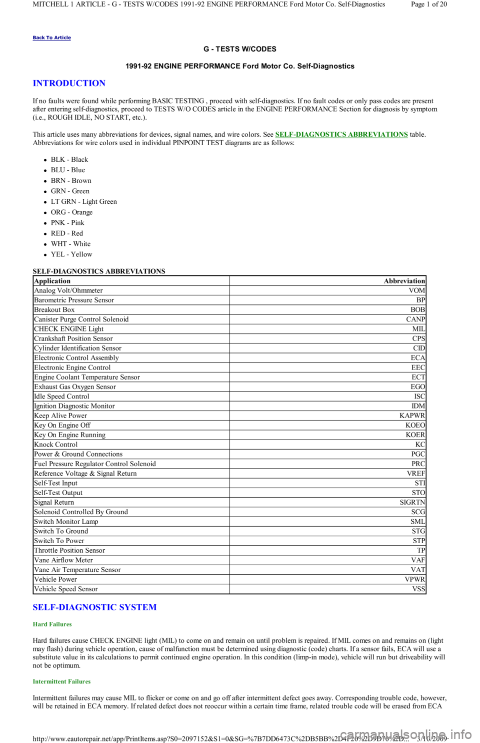
This article uses many abbreviations for devices, signal names, and wire colors. See SELF
-DIAGNOSTICS ABBREVIATIONS table.
Abbreviations for wire colors used in individual PINPOINT TEST diagrams are as follows:
BLK - Black
BLU - Blue
BRN - Brown
GRN - Green
LT GRN - Light Green
ORG - Orange
PNK - Pink
RED - Red
WHT - White
YEL - Yellow
SELF-DIAGNOSTICS ABBREVIATIONS
SELF-DIAGNOSTIC SYSTEM
Hard Failures
Hard failures cause CHECK ENGINE light (MIL) to come on and remain on until problem is repaired. If MIL comes on and remains on (light
may flash) during vehicle operation, cause of malfunction must be determined using diagnostic (code) charts. If a sensor fails, ECA will use a
substitute value in its calculations to permit continued engine operation. In this condition (limp-in mode), vehicle will run but driveability will
not be optimum.
Intermittent Failures
Intermittent failures may cause MIL to flicker or come on and go off after intermittent defect goes away. Corresponding trouble code, however,
will be retained in ECA memory. If related defect does not reoccur within a certain time frame, related trouble code will be erased from ECA
ApplicationAbbreviation
Analog Volt/OhmmeterVOM
Barometric Pressure SensorBP
Breakout BoxBOB
Canister Purge Control SolenoidCANP
CHECK ENGINE LightMIL
Crankshaft Position SensorCPS
Cylinder Identification SensorCID
Electronic Control AssemblyECA
Electronic Engine ControlEEC
Engine Coolant Temperature SensorECT
Exhaust Gas Oxygen SensorEGO
Idle Speed ControlISC
Ignition Diagnostic MonitorIDM
Keep Alive PowerKAPWR
Key On Engine OffKOEO
Key On Engine RunningKOER
Knock ControlKC
Power & Ground ConnectionsPGC
Fuel Pressure Regulator Control SolenoidPRC
Reference Voltage & Signal ReturnVREF
Self-Test InputSTI
Self-Test OutputSTO
Signal ReturnSIGRTN
Solenoid Controlled By GroundSCG
Switch Monitor LampSML
Switch To GroundSTG
Switch To PowerSTP
Throttle Position SensorTP
Vane Airflow MeterVAF
Vane Air Temperature SensorVAT
Vehicle PowerVPWR
Vehicle Speed SensorVSS
Page 1 of 20 MITCHELL 1 ARTICLE - G - TESTS W/CODES 1991-92 ENGINE PERFORMANCE Ford Motor Co. Self-Diagnostics
3/10/2009 http://www.eautorepair.net/app/PrintItems.asp?S0=2097152&S1=0&SG=%7B7DD6473C%2DB5BB%2D4F20%2D9D70%2D
...
Page 170 of 454
Engine control system communicates malfunctions to technician through service codes. These service codes are 2-digit numbers representing a
particular defect. Service codes are transmitted through STO connector.
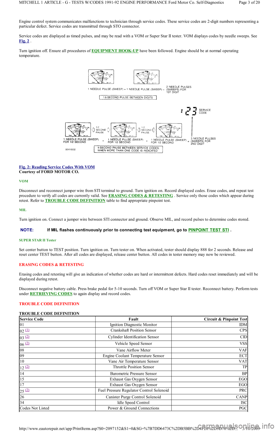
Service codes are displayed as timed pulses, and may be read with a VOM or Super Star II tester. VOM displays codes by needle sweeps. See
Fig. 2
.
Turn ignition off. Ensure all procedures of EQUIPMENT HOOK
-UP have been followed. Engine should be at normal operating
temperature.
Fig. 2: Reading Service Codes With VOM
Courtesy of FORD MOTOR CO.
VOM
Disconnect and reconnect jumper wire from STI terminal to ground. Turn ignition on. Record displayed codes. Erase codes, and repeat test
procedure to verify all codes are currently valid. See ERASING CODES & RETESTING . Service only those codes which appear during
retest. Refer to TROUBLE CODE DEFINITION
table to find appropriate pinpoint test.
MIL
Turn ignition on. Connect a jumper wire between STI connector and ground. Observe MIL, and record pulses to determine codes stored.
SUPER STAR II Tester
Set center button to TEST position. Turn ignition on. Turn tester on. When activated, tester should display 888 for 2 seconds. Release and
reset center TEST button. After all codes are displayed, release center button. All codes in tester memory may now be reviewed.
ERASING CODES & RETESTING
Erasing codes and retesting will give an indication of whether codes are hard or intermittent defects. Hard codes reset immediately and will be
displayed during retest.
Disconnect negative battery cable. Press brake pedal for 5-10 seconds. Turn off VOM or Super Star II tester. Reconnect battery. Perform tests
under RETRIEVING CODES
to again display and record codes.
TROUBLE CODE DEFINITION
TROUBLE CODE DEFINITION
NOTE:If MIL flashes continuously prior to connecting test equipm ent, go to PINPOINT T EST ST I .
Service CodeFaultCircuit & Pinpoint Test
01Ignition Diagnostic MonitorIDM
02 (1) Crankshaft Position SensorCPS
03 (2) Cylinder Identification SensorCID
06 (2) Vehicle Speed SensorVSS
08Vane Airflow MeterVAF
09Engine Coolant Temperature SensorECT
10Vane Air Temperature SensorVAT
12 (2) Throttle Position SensorTP
14Barometric Pressure SensorBP
15Exhaust Gas Oxygen SensorEGO
17Exhaust Gas Oxygen SensorEGO
25 (2) Fuel Pressure Regulator Control SolenoidPRC
26Canister Purge Control SolenoidCANP
34Idle Speed ControlISC
Codes Not ListedPower & Ground ConnectionsPGC
Page 3 of 20 MITCHELL 1 ARTICLE - G - TESTS W/CODES 1991-92 ENGINE PERFORMANCE Ford Motor Co. Self-Diagnostics
3/10/2009 http://www.eautorepair.net/app/PrintItems.asp?S0=2097152&S1=0&SG=%7B7DD6473C%2DB5BB%2D4F20%2D9D70%2D
...