check engine light FORD FIESTA 1989 Service Manual PDF
[x] Cancel search | Manufacturer: FORD, Model Year: 1989, Model line: FIESTA, Model: FORD FIESTA 1989Pages: 296, PDF Size: 10.65 MB
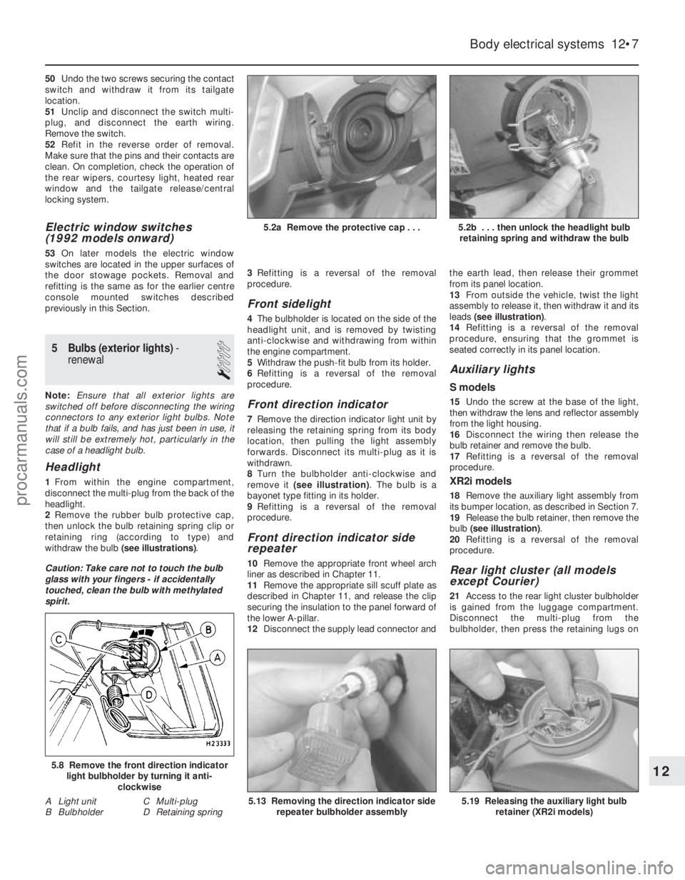
Page 239 of 296
windows (early models) and the tailgate
remote release mechanism, where fitted.
19Disconnect the battery negative (earth)
lead (refer to Chapter 5A, Section 1).
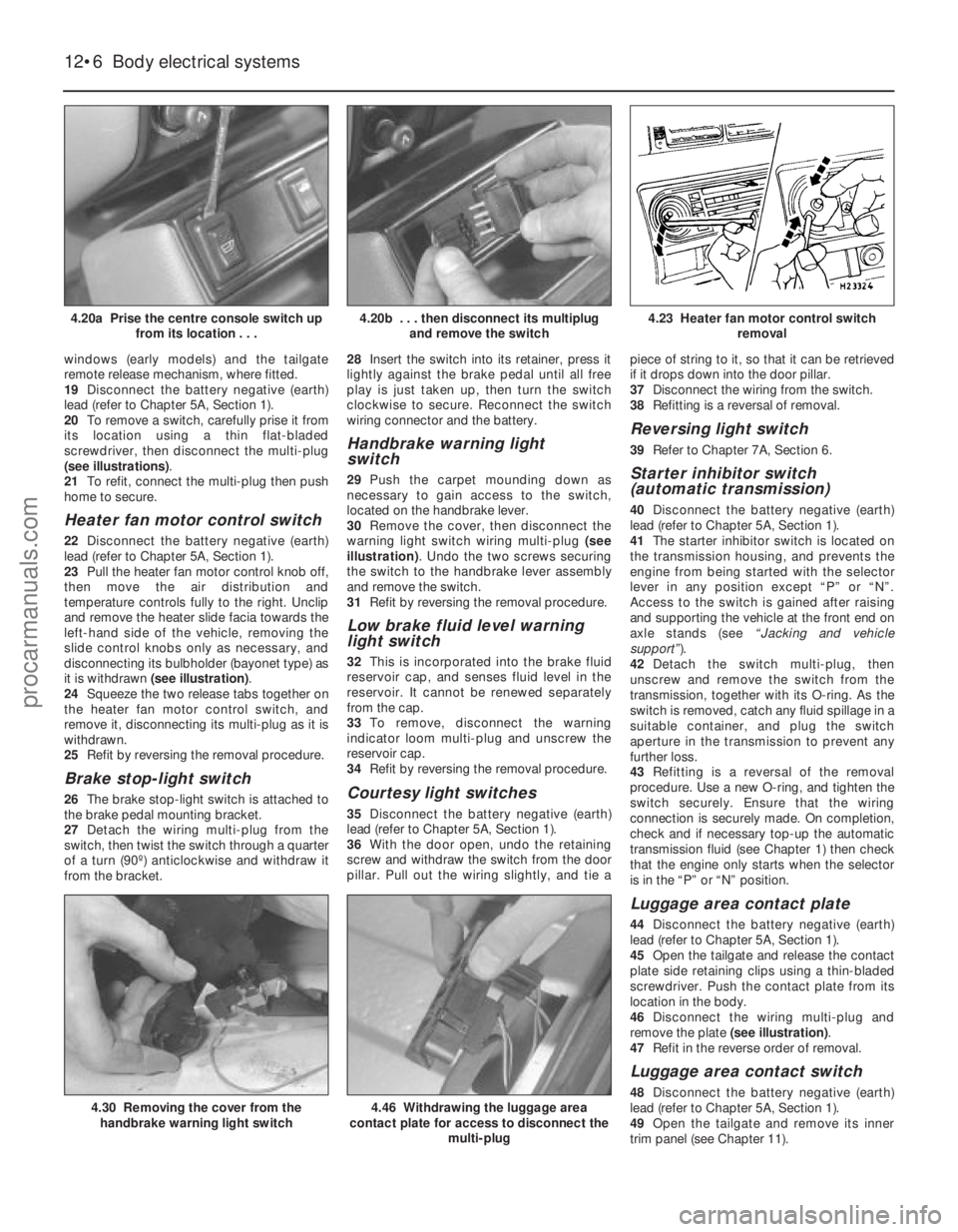
20 To remove a switch, carefully prise it from
its location using a thin flat-bladed
screwdriver, then disconnect the multi-plug
(see illustrations) .
21 To refit, connect the multi-plug then push
home to secure.
Heater fan motor control switch
22 Disconnect the battery negative (earth)
lead (refer to Chapter 5A, Section 1).
23 Pull the heater fan motor control knob off,
then move the air distribution and
temperature controls fully to the right. Unclip
and remove the heater slide facia towards the
left-hand side of the vehicle, removing the
slide control knobs only as necessary, and
disconnecting its bulbholder (bayonet type) as
it is withdrawn (see illustration) .
24 Squeeze the two release tabs together on
the heater fan motor control switch, and
remove it, disconnecting its multi-plug as it is
withdrawn.
25 Refit by reversing the removal procedure.
Brake stop-light switch
26The brake stop-light switch is attached to
the brake pedal mounting bracket.
27 Detach the wiring multi-plug from the
switch, then twist the switch through a quarter
of a turn (90º) anticlockwise and withdraw it
from the bracket. 28
Insert the switch into its retainer, press it
lightly against the brake pedal until all free
play is just taken up, then turn the switch
clockwise to secure. Reconnect the switch
wiring connector and the battery.
Handbrake warning light
switch
29 Push the carpet mounding down as
necessary to gain access to the switch,
located on the handbrake lever.
30 Remove the cover, then disconnect the
warning light switch wiring multi-plug (see
illustration) . Undo the two screws securing
the switch to the handbrake lever assembly
and remove the switch.
31 Refit by reversing the removal procedure.
Low brake fluid level warning
light switch
32This is incorporated into the brake fluid
reservoir cap, and senses fluid level in the
reservoir. It cannot be renewed separately
from the cap.
33 To remove, disconnect the warning
indicator loom multi-plug and unscrew the
reservoir cap.
34 Refit by reversing the removal procedure.
Courtesy light switches
35Disconnect the battery negative (earth)
lead (refer to Chapter 5A, Section 1).
36 With the door open, undo the retaining
screw and withdraw the switch from the door
pillar. Pull out the wiring slightly, and tie a piece of string to it, so that it can be retrieved
if it drops down into the door pillar.
37
Disconnect the wiring from the switch.
38 Refitting is a reversal of removal.
Reversing light switch
39Refer to Chapter 7A, Section 6.
Starter inhibitor switch
(automatic transmission)
40Disconnect the battery negative (earth)
lead (refer to Chapter 5A, Section 1).
41 The starter inhibitor switch is located on
the transmission housing, and prevents the
engine from being started with the selector
lever in any position except “P” or “N”.
Access to the switch is gained after raising
and supporting the vehicle at the front end on
axle stands (see “Jacking and vehicle
support” ).
42 Detach the switch multi-plug, then
unscrew and remove the switch from the
transmission, together with its O-ring. As the
switch is removed, catch any fluid spillage in a
suitable container, and plug the switch
aperture in the transmission to prevent any
further loss.
43 Refitting is a reversal of the removal
procedure. Use a new O-ring, and tighten the
switch securely. Ensure that the wiring
connection is securely made. On completion,
check and if necessary top-up the automatic
transmission fluid (see Chapter 1) then check
that the engine only starts when the selector
is in the “P” or “N” position.
Luggage area contact plate
44 Disconnect the battery negative (earth)
lead (refer to Chapter 5A, Section 1).
45 Open the tailgate and release the contact
plate side retaining clips using a thin-bladed
screwdriver. Push the contact plate from its
location in the body.
46 Disconnect the wiring multi-plug and
remove the plate (see illustration).
47 Refit in the reverse order of removal.
Luggage area contact switch
48Disconnect the battery negative (earth)
lead (refer to Chapter 5A, Section 1).
49 Open the tailgate and remove its inner
trim panel (see Chapter 11).
12•6 Body electrical systems
4.46 Withdrawing the luggage area
contact plate for access to disconnect the
multi-plug4.30 Removing the cover from thehandbrake warning light switch
4.23 Heater fan motor control switch removal4.20b . . . then disconnect its multiplugand remove the switch4.20a Prise the centre console switch up from its location . . .
1595Ford Fiesta Remakeprocarmanuals.com
http://vnx.su
Page 240 of 296
50Undo the two screws securing the contact
switch and withdraw it from its tailgate
location.
51 Unclip and disconnect the switch multi-
plug, and disconnect the earth wiring.
Remove the switch.
52 Refit in the reverse order of removal.
Make sure that the pins and their contacts are
clean. On completion, check the operation of
the rear wipers, courtesy light, heated rear
window and the tailgate release/central
locking system.
Electric window switches
(1992 models onward)
53 On later models the electric window
switches are located in the upper surfaces of
the door stowage pockets. Removal and
refitting is the same as for the earlier centre
console mounted switches described
previously in this Section.
5 Bulbs (exterior lights) -
renewal
1
Note: Ensure that all exterior lights are
switched off before disconnecting the wiring
connectors to any exterior light bulbs. Note
that if a bulb fails, and has just been in use, it
will still be extremely hot, particularly in the
case of a headlight bulb.
Headlight
1 From within the engine compartment,
disconnect the multi-plug from the back of the
headlight.
2 Remove the rubber bulb protective cap,
then unlock the bulb retaining spring clip or
retaining ring (according to type) and
withdraw the bulb (see illustrations).
Caution: Take care not to touch the bulb
glass with your fingers - if accidentally
touched, clean the bulb with methylated
spirit. 3
Refitting is a reversal of the removal
procedure.
Front sidelight
4 The bulbholder is located on the side of the
headlight unit, and is removed by twisting
anti-clockwise and withdrawing from within
the engine compartment.
5 Withdraw the push-fit bulb from its holder.
6 Refitting is a reversal of the removal
procedure.
Front direction indicator
7 Remove the direction indicator light unit by
releasing the retaining spring from its body
location, then pulling the light assembly
forwards. Disconnect its multi-plug as it is
withdrawn.
8 Turn the bulbholder anti-clockwise and
remove it (see illustration) . The bulb is a
bayonet type fitting in its holder.
9 Refitting is a reversal of the removal
procedure.
Front direction indicator side
repeater
10 Remove the appropriate front wheel arch
liner as described in Chapter 11.
11 Remove the appropriate sill scuff plate as
described in Chapter 11, and release the clip
securing the insulation to the panel forward of
the lower A-pillar.
12 Disconnect the supply lead connector and the earth lead, then release their grommet
from its panel location.
13
From outside the vehicle, twist the light
assembly to release it, then withdraw it and its
leads (see illustration) .
14 Refitting is a reversal of the removal
procedure, ensuring that the grommet is
seated correctly in its panel location.
Auxiliary lights
S models
15 Undo the screw at the base of the light,
then withdraw the lens and reflector assembly
from the light housing.
16 Disconnect the wiring then release the
bulb retainer and remove the bulb.
17 Refitting is a reversal of the removal
procedure.
XR2i models
18 Remove the auxiliary light assembly from
its bumper location, as described in Section 7.
19 Release the bulb retainer, then remove the
bulb (see illustration) .
20 Refitting is a reversal of the removal
procedure.
Rear light cluster (all models
except Courier)
21 Access to the rear light cluster bulbholder
is gained from the luggage compartment.
Disconnect the multi-plug from the
bulbholder, then press the retaining lugs on
Body electrical systems 12•7
5.2b . . . then unlock the headlight bulb retaining spring and withdraw the bulb5.2a Remove the protective cap . . .
5.19 Releasing the auxiliary light bulb retainer (XR2i models)5.13 Removing the direction indicator siderepeater bulbholder assembly
5.8 Remove the front direction indicatorlight bulbholder by turning it anti-
clockwise
A Light unit C Multi-plug
B Bulbholder D Retaining spring12
1595Ford Fiesta Remakeprocarmanuals.com
http://vnx.su
Page 270 of 296

1595 Ford Fiesta Remake
REF•4General repair procedures
Whenever servicing, repair or overhaul work
is carried out on the car or its components,
observe the following procedures and
instructions. This will assist in carrying out the
operation efficiently and to a professional
standar d of workmanship.
Joint mating faces and gaskets
When separating components at their
mating faces, never insert screwdrivers or
similar implements into the joint between the
faces in order to prise them apart. This can
cause severe damage which results in oil
leaks, coolant leaks, etc upon reassembly.
Separation is usually achieved by tapping
along the joint with a soft-faced hammer in
or der to break the seal. However, note that
this method may not be suitable where
dowels are used for component location.
Wher e a gasket is used between the mating
faces of two components, a new one must be
fitted on reassembly; fit it dry unless otherwise
stated in the repair procedure. Make sure that
the mating faces are clean and dry, with all
traces of old gasket removed. When cleaning a
joint face, use a tool which is unlikely to score
or damage the face, and remove any burrs or
nicks with an oilstone or fine file.
Make sure that tapped holes are cleaned
with a pipe cleaner, and keep them free of
jointing compound, if this is being used,
unless specifically instructed otherwise. Ensur e that all orifices, channels or pipes
ar e clear, and blow through them, preferably
using compressed air.
Oil seals
Oil seals can be removed by levering them
out with a wide flat-bladed screwdriver or
similar implement. Alternatively, a number of
self-tapping screws may be screwed into the
seal, and these used as a purchase for pliers or
some similar device in order to pull the seal free.
Whenever an oil seal is removed from its
working location, either individually or as part
of an assembly, it should be renewed. The very fine sealing lip of the seal is easily
damaged, and will not seal if the surface it
contacts is not completely clean and free fr om
scratches, nicks or grooves. If the original
sealing surface of the component cannot be
restor ed, and the manufacturer has not made
pr ovision for slight relocation of the seal
r elative to the sealing surface, the component
should be renewed.
Protect the lips of the seal from any surface
which may damage them in the course of
fitting. Use tape or a conical sleeve where
possible. Lubricate the seal lips with oil before
fitting and, on dual-lipped seals, fill the space
between the lips with grease.
Unless otherwise stated, oil seals must be
fitted with their sealing lips toward the
lubricant to be sealed.
Use a tubular drift or block of wood of the
appr opriate size to install the seal and, if the
seal housing is shouldered, drive the seal
down to the shoulder. If the seal housing is unshoulder
ed, the seal should be fitted with
its face flush with the housing top face (unless
otherwise instructed).
Screw threads and fastenings
Seized nuts, bolts and screws are quite a
common occurrence where corrosion has set
in, and the use of penetrating oil or releasing
fluid will often overcome this problem if the
of fending item is soaked for a while before
attempting to release it. The use of an impact
driver may also provide a means of releasing
such stubborn fastening devices, when used
in conjunction with the appropriate
scr ewdriver bit or socket. If none of these
methods works, it may be necessary to resort
to the careful application of heat, or the use of
a hacksaw or nut splitter device. Studs are usually removed by locking two
nuts together on the threaded part, and then
using a spanner on the lower nut to unscrew
the stud. Studs or bolts which have broken off
below the surface of the component in which
they are mounted can sometimes be removed
using a stud extractor. Always ensure that a
blind tapped hole is completely free from oil,
gr ease, water or other fluid before installing
the bolt or stud. Failure to do this could cause
the housing to crack due to the hydraulic
action of the bolt or stud as it is screwed in. When tightening a castellated nut to accept
a split pin, tighten the nut to the specified
tor que, where applicable, and then tighten
further to the next split pin hole. Never slacken
the nut to align the split pin hole, unless stated
in the repair procedure.
When checking or retightening a nut or bolt
to a specified torque setting, slacken the nut
or bolt by a quarter of a turn, and then
r etighten to the specified setting. However,
this should not be attempted where angular
tightening has been used. For some screw fastenings, notably
cylinder head bolts or nuts, torque wrench
settings are no longer specified for the latter
stages of tightening, “angle-tightening” being
called up instead. Typically, a fairly low torque wr ench setting will be applied to the
bolts/nuts in the correct sequence, followed
by one or more stages of tightening through
specified angles.
Locknuts, locktabs and washers
Any fastening which will rotate against a
component or housing during tightening
should always have a washer between it and
the relevant component or housing. Spring or split washers should always be
r enewed when they are used to lock a critical
component such as a big-end bearing
r etaining bolt or nut. Locktabs which are
folded over to retain a nut or bolt should
always be renewed.
Self-locking nuts can be re-used in non-
critical areas, providing resistance can be felt
when the locking portion passes over the bolt
or stud thread. However, it should be noted
that self-locking stiffnuts tend to lose their ef
fectiveness after long periods of use, and
should then be renewed as a matter of course.
Split pins must always be replaced with
new ones of the correct size for the hole. When thread-locking compound is found
on the threads of a fastener which is to be re-
used, it should be cleaned off with a wire
brush and solvent, and fresh compound
applied on reassembly.
Special tools
Some repair procedures in this manual
entail the use of special tools such as a press,
two or three-legged pullers, spring com-
pr essors, etc. Wherever possible, suitable
readily-available alternatives to the manu-
facturer’ s special tools are described, and are
shown in use. In some instances, where no
alter native is possible, it has been necessary
to resort to the use of a manufacturer’s tool, and this has been done for reasons of safety
as well as the efficient completion of the repair
operation. Unless you are highly-skilled and
have a thorough understanding of the
procedur es described, never attempt to
bypass the use of any special tool when the
pr ocedur e described specifies its use. Not
only is there a very great risk of personal
injury , but expensive damage could be
caused to the components involved.
Environmental considerations
When disposing of used engine oil, brake
fluid, antifreeze, etc, give due consideration to
any detrimental environmental effects. Do not,
for instance, pour any of the above liquids
down drains into the general sewage system,
or onto the ground to soak away. Many local
council refuse tips provide a facility for waste
oil disposal, as do some garages. If none of
these facilities are available, consult your local
Envir onmental Health Department, or the
National Rivers Authority, for further advice. With the universal tightening-up of legis-
lation regarding the emission of environmen-
tally-harmful substances from motor vehicles,
most vehicles have tamperproof devices fitted
to the main adjustment points of the fuel
system. These devices are primarily designed
to prevent unqualified persons from adjusting the fuel/air mixture, with the chance of a
consequent increase in toxic emissions. If
such devices are found during servicing or
overhaul, they should, wherever possible, be
r enewed or refitted in accordance with the
manufacturer’ s requirements or current
legislation.
Note: It is
antisocial and
illegal to dump
oil down the
drain. To find
the location of
your local oil
recycling
bank, call this
number free.
procarmanuals.com
http://vnx.su
Page 276 of 296
1595 Ford Fiesta Remake
REF•10MOT test checks
This is a guide to getting your vehicle through the MOT test.
Obviously it will not be possible to examine the vehicle to the same
standar d as the professional MOT tester. However, working through
the following checks will enable you to identify any problem areas
befor e submitting the vehicle for the test.
Wher e a testable component is in borderline condition, the tester
has discretion in deciding whether to pass or fail it. The basis of such
discr etion is whether the tester would be happy for a close relative or
friend to use the vehicle with the component in that condition. If the
vehicle presented is clean and evidently well cared for, the tester may
be more inclined to pass a borderline component than if the vehicle is
scruffy and apparently neglected.
It has only been possible to summarise the test requirements her e,
based on the regulations in force at the time of printing. Test standards ar e becoming increasingly stringent, although there are some
exemptions for older vehicles. For full details obtain a copy of the Hay\
nes
publication Pass the MOT! (available from stockists of Haynes manuals).
An assistant will be needed to help carry out some of these checks.
The checks have been sub-divided into four categories, as follows:
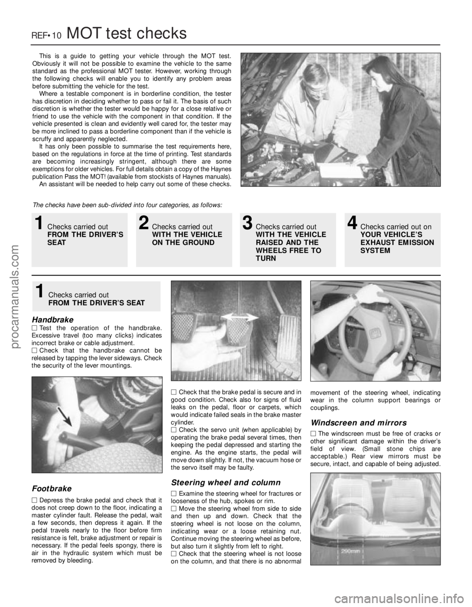
HandbrakeM Test the operation of the handbrake.
Excessive travel (too many clicks) indicates
incorr ect brake or cable adjustment.
M Check that the handbrake cannot be
r eleased by tapping the lever sideways. Check
the security of the lever mountings.
Footbrake
M Depr ess the brake pedal and check that it
does not creep down to the floor, indicating a master cylinder fault. Release the pedal, wait
a few seconds, then depress it again. If the
pedal travels nearly to the floor before firm
r esistance is felt, brake adjustment or repair is
necessary . If the pedal feels spongy, there is
air in the hydraulic system which must be
r emoved by bleeding. M
Check that the brake pedal is secure and in
good condition. Check also for signs of fluid
leaks on the pedal, floor or carpets, which
would indicate failed seals in the brake master
cylinder.
M Check the servo unit (when applicable) by
operating the brake pedal several times, then
keeping the pedal depressed and starting the
engine. As the engine starts, the pedal will
move down slightly. If not, the vacuum hose or
the servo itself may be faulty.
Steering wheel and column
M Examine the steering wheel for fractures or
looseness of the hub, spokes or rim.
M Move the steering wheel from side to side
and then up and down. Check that the
steering wheel is not loose on the column,
indicating wear or a loose retaining nut.
Continue moving the steering wheel as before,
but also turn it slightly from left to right.
M Check that the steering wheel is not loose
on the column, and that there is no abnormal movement of the steering wheel, indicating
wear in the column support bearings or
couplings.
W
indscreen and mirrors
M The windscreen must be free of cracks or
other significant damage within the driver’s
field of view. (Small stone chips are
acceptable.) Rear view mirrors must be
secur e, intact, and capable of being adjusted.
1Checks carried out
FROM THE DRIVER’S SEAT
1Checks carried out
FROM THE DRIVER’S
SEAT2Checks carried out
WITH THE VEHICLE
ON THE GROUND3Checks carried out
WITH THE VEHICLE
RAISED AND THE
WHEELS FREE TO
TURN4Checks carried out on
YOUR VEHICLE’S
EXHAUST EMISSION
SYSTEM
procarmanuals.com
http://vnx.su
Page 286 of 296
1595 Ford Fiesta Remake
REF•20Fault finding
Electrical system
Note:For problems associated with the starting system, refer to the
faults listed under “Engine” earlier in this Section.
Battery will not hold a charge for more than a few
days
m m Battery defective internally (Chapter 5A).
m
m Battery terminal connections loose or corroded (Chapter 5A).
m
m Auxiliary drivebelt worn or incorrectly-adjusted (Chapter 1).
m
m Alternator not charging at correct output (Chapter 5A).
m
m Alternator or voltage regulator faulty (Chapter 5A).
m
m Short-circuit causing continual battery drain (Chapters 5A and 12).
Ignition (no-charge) warning light remains
illuminated with engine running
m mAuxiliary drivebelt broken, worn, or incorrectly-adjusted (Chap-
ter 1).
m m Alternator brushes worn, sticking, or dirty (Chapter 5A).
m
m Alternator brush springs weak or broken (Chapter 5A).
m
m Internal fault in alternator or voltage regulator (Chapter 5A).
m
m Broken, disconnected, or loose wiring in charging circuit (Chap-
ter 5A).
Ignition (no-charge) warning light fails to come on
m mWarning light bulb blown (Chapter 12).
m
m Broken, disconnected, or loose wiring in warning light circuit
(Chapters 5A and 12).
m m Alternator faulty (Chapter 5A).
Lights inoperative
m
mBulb blown (Chapter 12).
m
m Corrosion of bulb or bulbholder contacts (Chapter 12).
m
m Blown fuse (Chapter 12).
m
m Faulty relay (Chapter 12).
m
m Broken, loose, or disconnected wiring (Chapter 12).
m
m Faulty switch (Chapter 12).
Instrument readings inaccurate or erratic
Instrument readings increase with engine speed
m
mFaulty voltage regulator (Chapter 12).
Fuel or temperature gauges give no reading
m
mFaulty gauge sender unit (Chapters 3 or 4A, 4B, 4C, or 4D).
m
m Wiring open-circuit (Chapter 12).
m
m Faulty gauge (Chapter 12).
Fuel or temperature gauges give continuous maximum
reading
m mFaulty gauge sender unit (Chapters 3 or 4A, 4B, 4C, or 4D).
m
m Wiring short-circuit (Chapter 12).
m
m Faulty gauge (Chapter 12).
Horn inoperative, or unsatisfactory in operation
Horn fails to operate
m
mBlown fuse (Chapter 12).
m
m Cable or cable connections loose, broken or disconnected
(Chapter 12).
m m Faulty horn (Chapter 12).
Horn emits intermittent or unsatisfactory sound
m
mCable connections loose (Chapter 12).
m
m Horn mountings loose (Chapter 12).
m
m Faulty horn (Chapter 12).
Horn operates all the time
m
mHorn push either earthed or stuck down (Chapter 12).
m
m Horn cable to horn push earthed (Chapter 12).
Windscreen/tailgate wipers inoperative or
unsatisfactory in operation
Wipers fail to operate, or operate very slowly
m mWiper blades stuck to screen, or linkage seized or binding
(Chapter 12).
m m Blown fuse (Chapter 12).
m
m Cable or cable connections loose, broken or disconnected
(Chapter 12).
m m Faulty relay (Chapter 12).
m
m Faulty wiper motor (Chapter 12).
Wiper blades sweep over too large or too small an area of
the glass
m mWiper arms incorrectly-positioned on spindles (Chapter 1).
m
m Excessive wear of wiper linkage (Chapter 1).
m
m Wiper motor or linkage mountings loose or insecure (Chapter 12).
Wiper blades fail to clean the glass effectively
m
mWiper blade rubbers worn or perished ( “Weekly Checks”).
m
m Wiper arm tension springs broken, or arm pivots seized (Chap-
ter 1).
m m Insufficient windscreen washer additive to adequately remove
road film ( “Weekly Checks” ).
Windscreen/tailgate washers inoperative, or
unsatisfactory in operation
One or more washer jets inoperative
m mBlocked washer jet ( “Weekly Checks”or Chapter 1).
m
m Disconnected, kinked or restricted fluid hose (Chapter 1).
m
m Insufficient fluid in washer reservoir ( “Weekly Checks”).
Washer pump fails to operate
m
mBroken or disconnected wiring or connections (Chapter 12).
m
m Blown fuse (Chapter 12).
m
m Faulty washer switch (Chapter 12).
m
m Faulty washer pump (Chapter 12).
Washer pump runs for some time before fluid is emitted
from jets
m mFaulty one-way valve in fluid supply hose (Chapter 12).
Electric windows inoperative, or unsatisfactory in
operation
Window glass will only move in one direction
m mFaulty switch (Chapter 12).
Window glass slow to move
m
mIncorrectly-adjusted door glass guide channels (Chapter 11).
m
m Regulator seized or damaged, or in need of lubrication (Chapter
11).
m m Door internal components or trim fouling regulator (Chapter 11).
m
m Faulty motor (Chapter 12).
Window glass fails to move
m
mIncorrectly-adjusted door glass guide channels (Chapter 11).
m
m Blown fuse (Chapter 12).
m
m Faulty relay (Chapter 12).
m
m Broken or disconnected wiring or connections (Chapter 12).
m
m Faulty motor (Chapter 12).
procarmanuals.com
http://vnx.su
Page 293 of 296
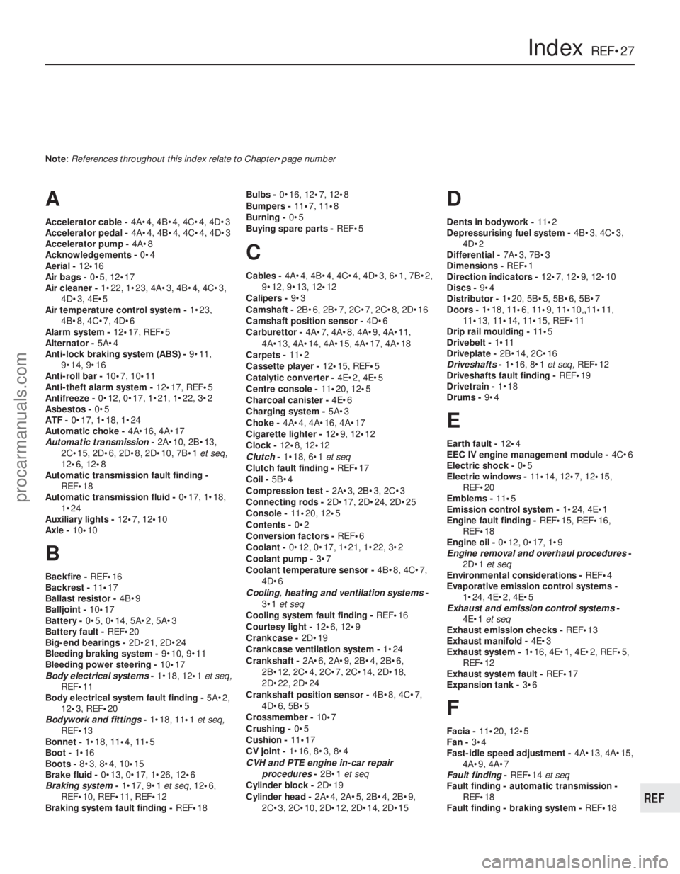
1595 Ford Fiesta Remake
IndexREF•27
REF
Note: References throughout this index relate to Chapter•page number
A
Accelerator cable -4A•4, 4B•4, 4C•4, 4D•3
Accelerator pedal - 4A•4, 4B•4, 4C•4, 4D•3
Accelerator pump - 4A•8
Acknowledgements - 0•4
Aerial - 12•16
Air bags - 0•5, 12•17
Air cleaner - 1•22, 1•23, 4A•3, 4B•4, 4C•3,
4D•3, 4E•5
Air temperature control system - 1•23,
4B•8, 4C•7, 4D•6
Alarm system - 12•17, REF• 5
Alternator - 5A•4
Anti-lock braking system (ABS) - 9•11,
9•14, 9•16
Anti-roll bar - 10•7, 10•11
Anti-theft alarm system - 12•17, REF•5
Antifreeze - 0•12, 0•17, 1•21, 1•22, 3•2
Asbestos - 0•5
ATF - 0•17, 1•18, 1•24
Automatic choke - 4A•16, 4A•17
Automatic transmission -2A•10, 2B•13,
2C•15, 2D•6, 2D•8, 2D•10, 7B•1 et seq,
12 •6, 12 •8
Automatic transmission fault finding - REF• 18
Automatic transmission fluid - 0•17, 1•18,
1•24
Auxiliary lights - 12•7, 12•10
Axle - 10•10
B
Backfire - REF•16
Backrest - 11•17
Ballast resistor - 4B•9
Balljoint - 10•17
Battery - 0•5, 0•14, 5A•2, 5A•3
Battery fault - REF•20
Big-end bearings - 2D•21, 2D•24
Bleeding braking system - 9•10, 9•11
Bleeding power steering - 10•17
Body electrical systems -1•18, 12 •1et seq,
REF• 11
Body electrical system fault finding - 5A•2,
12 •3, REF •20
Bodywork and fittings -1•18, 11 •1et seq,
REF• 13
Bonnet - 1•18, 11•4,11•5
Boot - 1•16
Boots - 8•3, 8•4, 10 •15
Brake fluid - 0•13, 0•17, 1•26, 12 •6
Braking system -1•17, 9•1 et seq, 12•6,
REF• 10, REF•11, REF• 12
Braking system fault finding - REF•18 Bulbs -
0•16, 12 •7,12•8
Bumpers - 11•7, 11•8
Burning - 0•5
Buying spare parts - REF•5
C
Cables -4A•4, 4B•4, 4C•4, 4D•3, 6•1, 7B•2,
9•12, 9•13, 12 •12
Calipers - 9•3
Camshaft - 2B•6, 2B•7, 2C•7, 2C•8, 2D•16
Camshaft position sensor - 4D•6
Carburettor - 4A•7, 4A•8, 4A•9, 4A•11,
4A•13, 4A•14, 4A•15, 4A•17, 4A•18
Carpets - 11•2
Cassette player - 12•15, REF •5
Catalytic converter - 4E•2, 4E•5
Centre console - 11•20, 12 •5
Charcoal canister - 4E•6
Charging system - 5A•3
Choke - 4A•4, 4A•16, 4A•17
Cigarette lighter - 12•9, 12 •12
Clock - 12•8, 12•12
Clutch -1•18, 6•1 et seq
Clutch fault finding - REF•17
Coil - 5B•4
Compression test - 2A•3, 2B•3, 2C•3
Connecting rods - 2D•17, 2D•24, 2D•25
Console - 11•20, 12•5
Contents - 0•2
Conversion factors - REF•6
Coolant - 0•12, 0•17, 1•21, 1•22, 3•2
Coolant pump - 3•7
Coolant temperature sensor - 4B•8, 4C•7,
4D•6
Cooling ,heating and ventilation systems -
3•1 et seq
Cooling system fault finding - REF•16
Courtesy light - 12•6, 12•9
Crankcase - 2D•19
Crankcase ventilation system - 1•24
Crankshaft - 2A•6, 2A•9, 2B•4, 2B•6,
2B•12, 2C•4, 2C•7, 2C•14, 2D•18,
2D•22, 2D•24
Crankshaft position sensor - 4B•8, 4C•7,
4D•6, 5B•5
Crossmember - 10•7
Crushing - 0•5
Cushion - 11•17
CV joint - 1•16, 8•3, 8•4
CVH and PTE engine in-car repair
procedures -2B•1 et seq
Cylinder block - 2D•19
Cylinder head - 2A•4, 2A•5, 2B•4, 2B•9,
2C•3, 2C•10, 2D•12, 2D•14, 2D•15
D
Dents in bodywork - 11•2
Depressurising fuel system - 4B•3, 4C•3,
4D•2
Differential - 7A•3, 7B•3
Dimensions - REF•1
Direction indicators - 12•7, 12•9, 12•10
Discs - 9•4
Distributor - 1•20, 5B•5, 5B•6, 5B•7
Doors - 1•18, 11• 6,11•9, 11 •10,,11 •11,
11 •13, 11•14, 11•15, REF •11
Drip rail moulding - 11•5
Drivebelt - 1•11
Driveplate - 2B•14, 2C•16
Driveshafts -1•16, 8•1 et seq,REF•12
Driveshafts fault finding - REF•19
Drivetrain - 1•18
Drums - 9•4
E
Earth fault - 12•4
EEC IV engine management module - 4C•6
Electric shock - 0•5
Electric windows - 11•14, 12 •7, 12•15,
REF•20
Emblems - 11•5
Emission control system - 1•24, 4E•1
Engine fault finding - REF•15, REF•16,
REF •18
Engine oil - 0•12, 0•17, 1•9
Engine removal and overhaul procedures -
2D•1 et seq
Environmental considerations - REF•4
Evaporative emission control systems - 1•24, 4E•2, 4E•5
Exhaust and emission control systems -
4E•1 et seq
Exhaust emission checks - REF•13
Exhaust manifold - 4E•3
Exhaust system - 1•16, 4E•1, 4E•2, REF •5,
REF •12
Exhaust system fault - REF•17
Expansion tank - 3•6
F
Facia - 11•20, 12 •5
Fan - 3•4
Fast-idle speed adjustment - 4A•13, 4A•15,
4A•9, 4A•7
Fault finding - REF•14et seq
Fault finding - automatic transmission -
REF •18
Fault finding - braking system - REF•18
procarmanuals.com
http://vnx.su
Page 294 of 296
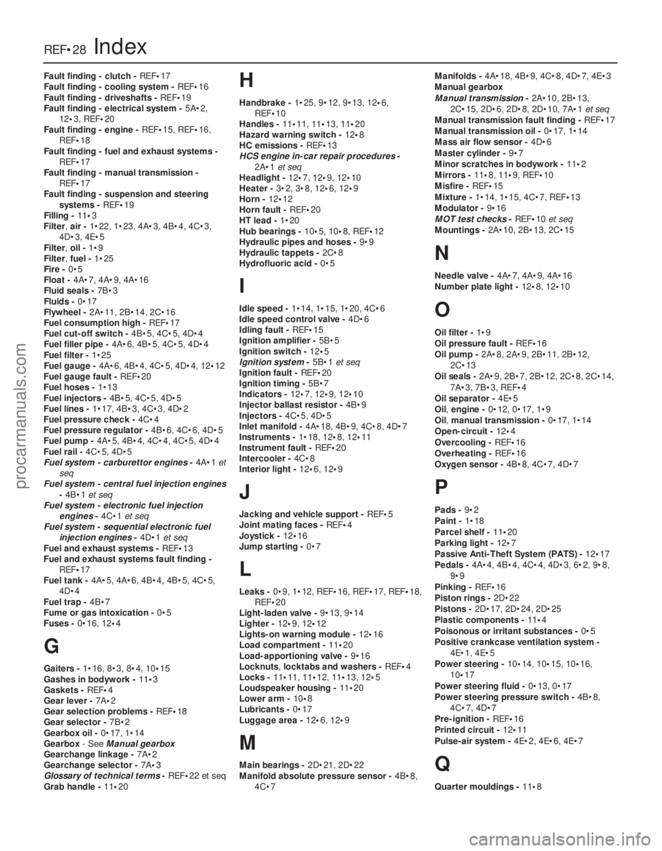
Fault finding - clutch - REF•17
Fault finding - cooling system - REF•16
Fault finding - driveshafts - REF•19
Fault finding - electrical system - 5A•2,
12 •3, REF •20
Fault finding - engine - REF•15, REF•16,
REF•18
Fault finding - fuel and exhaust systems -
REF•17
Fault finding - manual transmission - REF•17
Fault finding - suspension and steering
systems - REF•19
Filling - 11•3
Filter, air -1•22, 1•23, 4A•3, 4B•4, 4C•3,
4D•3, 4E•5
Filter, oil -1•9
Filter, fuel -1•25
Fire - 0•5
Float - 4A•7, 4A•9, 4A•16
Fluid seals - 7B•3
Fluids - 0•17
Flywheel - 2A•11, 2B•14, 2C•16
Fuel consumption high - REF•17
Fuel cut-off switch - 4B•5, 4C•5, 4D•4
Fuel filler pipe - 4A•6, 4B•5, 4C•5, 4D•4
Fuel filter - 1•25
Fuel gauge - 4A•6, 4B•4, 4C•5, 4D•4, 12 •12
Fuel gauge fault - REF•20
Fuel hoses - 1•13
Fuel injectors - 4B•5, 4C•5, 4D•5
Fuel lines - 1•17, 4B•3, 4C•3, 4D•2
Fuel pressure check - 4C•4
Fuel pressure regulator - 4B•6, 4C•6, 4D•5
Fuel pump - 4A•5, 4B•4, 4C•4, 4C•5, 4D•4
Fuel rail - 4C•5, 4D•5
Fuel system - carburettor engines -4A•1 et
seq
Fuel system - central fuel injection engines
-4B•1 et seq
Fuel system - electronic fuel injection engines -4C•1 et seq
Fuel system - sequential electronic fuel
injection engines -4D•1 et seq
Fuel and exhaust systems - REF•13
Fuel and exhaust systems fault finding - REF•17
Fuel tank - 4A•5, 4A•6, 4B•4, 4B•5, 4C•5,
4D•4
Fuel trap - 4B•7
Fume or gas intoxication - 0•5
Fuses - 0•16, 12 •4
G
Gaiters - 1•16, 8•3, 8•4, 10 •15
Gashes in bodywork - 11•3
Gaskets - REF •4
Gear lever - 7A•2
Gear selection problems - REF•18
Gear selector - 7B•2
Gearbox oil - 0•17, 1•14
Gearbox - See Manual gearbox
Gearchange linkage - 7A•2
Gearchange selector - 7A•3
Glossary of technical terms - REF•22 et seq
Grab handle - 11•20
H
Handbrake - 1•25, 9•12, 9•13, 12 •6,
REF•10
Handles - 11•11, 11•13, 11 •20
Hazard warning switch - 12•8
HC emissions - REF•13
HCS engine in-car repair procedures -
2A•1 et seq
Headlight - 12•7, 12 •9, 12 •10
Heater - 3•2, 3•8, 12 •6, 12•9
Horn - 12•12
Horn fault - REF•20
HT lead - 1•20
Hub bearings - 10•5, 10•8, REF •12
Hydraulic pipes and hoses - 9•9
Hydraulic tappets - 2C•8
Hydrofluoric acid - 0•5
I
Idle speed -1•14, 1•15, 1•20, 4C•6
Idle speed control valve - 4D•6
Idling fault - REF•15
Ignition amplifier - 5B•5
Ignition switch - 12•5
Ignition system -5B•1 et seq
Ignition fault - REF•20
Ignition timing - 5B•7
Indicators - 12•7, 12•9, 12 •10
Injector ballast resistor - 4B•9
Injectors - 4C•5, 4D•5
Inlet manifold - 4A•18, 4B•9, 4C•8, 4D•7
Instruments - 1•18, 12•8, 12•11
Instrument fault - REF•20
Intercooler - 4C•8
Interior light - 12•6, 12 •9
J
Jacking and vehicle support - REF•5
Joint mating faces - REF•4
Joystick - 12•16
Jump starting - 0•7
L
Leaks -0•9, 1•12, REF •16, REF•17, REF•18,
REF•20
Light-laden valve - 9•13, 9•14
Lighter - 12•9, 12 •12
Lights-on warning module - 12•16
Load compartment - 11•20
Load-apportioning valve - 9•16
Locknuts ,locktabs and washers - REF•4
Locks - 11•11, 11•12, 11•13, 12 •5
Loudspeaker housing - 11•20
Lower arm - 10•8
Lubricants - 0•17
Luggage area - 12•6, 12•9
M
Main bearings - 2D•21, 2D•22
Manifold absolute pressure sensor - 4B•8,
4C•7 Manifolds -
4A•18, 4B•9, 4C•8, 4D•7, 4E•3
Manual gearbox
Manual transmission -2A•10, 2B•13,
2C•15, 2D•6, 2D•8, 2D•10, 7A•1 et seq
Manual transmission fault finding - REF•17
Manual transmission oil - 0•17, 1•14
Mass air flow sensor - 4D•6
Master cylinder - 9•7
Minor scratches in bodywork - 11•2
Mirrors - 11 •8, 11•9, REF •10
Misfire - REF•15
Mixture - 1•14, 1•15, 4C•7, REF•13
Modulator - 9•16
MOT test checks - REF•10et seq
Mountings - 2A•10, 2B•13, 2C•15
N
Needle valve - 4A•7, 4A•9, 4A•16
Number plate light - 12•8, 12 •10
O
Oil filter - 1•9
Oil pressure fault - REF•16
Oil pump - 2A•8, 2A•9, 2B•11, 2B•12,
2C•13
Oil seals - 2A•9, 2B•7, 2B•12, 2C•8, 2C•14,
7A•3, 7B•3, REF •4
Oil separator - 4E•5
Oil, engine - 0•12, 0•17, 1•9
Oil, manual transmission - 0•17, 1•14
Open-circuit - 12•4
Overcooling - REF•16
Overheating - REF•16
Oxygen sensor - 4B•8, 4C•7, 4D•7
P
Pads -9•2
Paint - 1•18
Parcel shelf - 11•20
Parking light - 12•7
Passive Anti-Theft System (PATS) - 12•17
Pedals - 4A•4, 4B•4, 4C•4, 4D•3, 6•2, 9•8,
9•9
Pinking - REF•16
Piston rings - 2D•22
Pistons - 2D•17, 2D•24, 2D•25
Plastic components - 11•4
Poisonous or irritant substances - 0•5
Positive crankcase ventilation system - 4E•1, 4E•5
Power steering - 10•14, 10•15, 10•16,
10 •17
Power steering fluid - 0•13, 0•17
Power steering pressure switch - 4B•8,
4C•7, 4D•7
Pre-ignition - REF•16
Printed circuit - 12•11
Pulse-air system - 4E•2, 4E•6, 4E•7
Q
Quarter mouldings - 11•8
REF•28Index
1595 Ford Fiesta Remakeprocarmanuals.com
http://vnx.su
Page 295 of 296
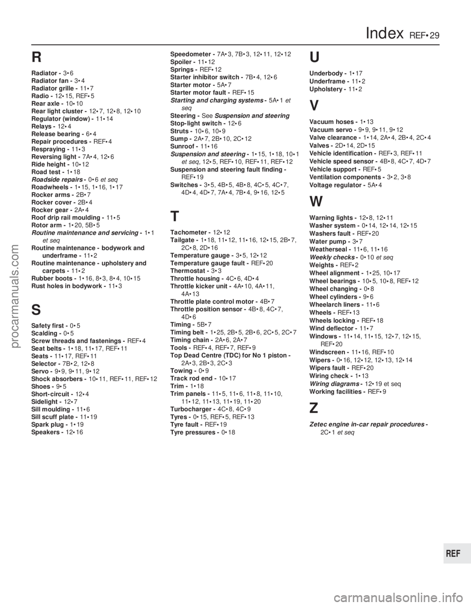
R
Radiator -3•6
Radiator fan - 3•4
Radiator grille - 11•7
Radio - 12•15, REF •5
Rear axle - 10•10
Rear light cluster - 12•7, 12•8, 12 •10
Regulator (window) - 11•14
Relays - 12•4
Release bearing - 6•4
Repair procedures - REF•4
Respraying - 11•3
Reversing light - 7A•4, 12•6
Ride height - 10•12
Road test - 1•18
Roadside repairs -0•6 et seq
Roadwheels - 1•15, 1•16, 1•17
Rocker arms - 2B•7
Rocker cover - 2B•4
Rocker gear - 2A•4
Roof drip rail moulding - 11•5
Rotor arm - 1•20, 5B•5
Routine maintenance and servicing -1•1
et seq
Routine maintenance - bodywork and
underframe - 11•2
Routine maintenance - upholstery and carpets - 11•2
Rubber boots - 1•16, 8•3, 8•4, 10 •15
Rust holes in bodywork - 11•3
S
Safety first - 0•5
Scalding - 0•5
Screw threads and fastenings - REF•4
Seat belts - 1•18, 11•17, REF•11
Seats - 11•17, REF •11
Selector - 7B•2, 12•8
Servo - 9•9, 9•11, 9•12
Shock absorbers - 10•11, REF •11, REF•12
Shoes - 9•5
Short-circuit - 12•4
Sidelight - 12•7
Sill moulding - 11•6
Sill scuff plate - 11•19
Spark plug - 1•19
Speakers - 12•16 Speedometer -
7A•3, 7B•3, 12•11, 12•12
Spoiler - 11•12
Springs - REF•12
Starter inhibitor switch - 7B•4, 12•6
Starter motor - 5A•7
Starter motor fault - REF•15
Starting and charging systems -5A•1 et
seq
Steering - See Suspension and steering
Stop-light switch - 12•6
Struts - 10•6, 10• 9
Sump - 2A•7, 2B•10, 2C•12
Sunroof - 11•16
Suspension and steering -1•15, 1•18, 10 •1
et seq, 12•5, REF •10, REF •11, REF• 12
Suspension and steering fault finding -
REF •19
Switches - 3•5, 4B•5, 4B•8, 4C•5, 4C•7,
4D•4, 4D•7, 7A•4, 7B•4, 9•16, 12 •5
T
Tachometer - 12•12
Tailgate - 1•18, 11•12, 11•16, 12•15, 2B•7,
2C•8, 2D•16
Temperature gauge - 3•5, 12•12
Temperature gauge fault - REF•20
Thermostat - 3•3
Throttle housing - 4C•6, 4D•4
Throttle kicker unit - 4A•10, 4A•11,
4A•13
Throttle plate control motor - 4B•7
Throttle position sensor - 4B•8, 4C•7,
4D•6
Timing - 5B•7
Timing belt - 1•25, 2B•5, 2B•6, 2C•5, 2C•7
Timing chain - 2A•6, 2A•7
Tools - REF•4, REF•7, REF•9
Top Dead Centre (TDC) for No 1 piston - 2A•3, 2B•3, 2C•3
Towing - 0•9
Track rod end - 10•17
Trim - 1•18
Trim panels - 11•5, 11 •6, 11•8, 11 •10,
11 •12, 11•13, 11•19, 11•20
Turbocharger - 4C•8, 4C•9
Tyres - 0•15, REF•5, REF •13
Tyre fault - REF•19
Tyre pressures - 0•18
U
Underbody -1•17
Underframe - 11•2
Upholstery - 11•2
V
Vacuum hoses - 1•13
Vacuum servo - 9•9, 9•11, 9•12
Valve clearance - 1•14, 2A•4, 2B•4, 2C•4
Valves - 2D•14, 2D•15
Vehicle identification - REF•3, REF •11
Vehicle speed sensor - 4B•8, 4C•7, 4D•7
Vehicle support - REF•5
Ventilation components - 3•2, 3•8
Voltage regulator - 5A•4
W
Warning lights - 12•8, 12•11
Washer system - 0•14, 12•14, 12•15
Washers fault - REF•20
Water pump - 3•7
Weatherseal - 11•6, 11•16
Weekly checks -0•10 et seq
Weights - REF•2
Wheel alignment - 1•25, 10•17
Wheel bearings - 10•5, 10 •8, REF •12
Wheel changing - 0•8
Wheel cylinders - 9•6
Wheelarch liners - 11•6
Wheels - REF•13
Wheels locking - REF•18
Wind deflector - 11•7
Windows - 11•14, 11•15, 12 •7, 12•15,
REF•20
Windscreen - 11•16, REF •10
Wipers - 0•16, 12• 12, 12•13, 12•14
Wipers fault - REF•20
Wiring check - 1•13
Wiring diagrams - 12•19 et seq
Working facilities - REF•9
Z
Zetec engine in-car repair procedures -
2C•1 et seq
IndexREF•29
REF
1595 Ford Fiesta Remakeprocarmanuals.com
http://vnx.su