check engine light FORD FIESTA 1989 Service Service Manual
[x] Cancel search | Manufacturer: FORD, Model Year: 1989, Model line: FIESTA, Model: FORD FIESTA 1989Pages: 296, PDF Size: 10.65 MB
Page 94 of 296
Plastigauge to the scale printed on the
Plastigauge envelope, to obtain the running
clearance (see illustration 17.15) . Compare it
to the Specifications, to make sure the
clearance is correct.
14 If the clearance is not as specified, seek
the advice of a Ford dealer or similar engine
reconditioning specialist - if the crankshaft
journals are in good condition it may be
possible simply to renew the shells to achieve
the correct clearance. If this is not possible,
the crankshaft must be reground by a
specialist, who can also supply the necessary
undersized shells. First though, make sure
that no dirt or oil was trapped between the
bearing shells and the connecting rod or cap
when the clearance was measured. Also,
recheck the crankpin diameter. If the
Plastigauge was wider at one end than the
other, the crankpin journal may be tapered.
15 Carefully scrape all traces of the
Plastigauge material off the journal and the
bearing surface. Be very careful not to scratch
the bearing - use your fingernail or the edge of a credit card.
Final piston/connecting rod
refitting
16 Make sure the bearing surfaces are
perfectly clean, then apply a uniform layer of
clean molybdenum disulphide-based grease,
engine assembly lubricant, or clean engine oil,
to both of them. You’ll have to push the piston
into the cylinder to expose the bearing surface
of the shell in the connecting rod.
17 Slide the connecting rod back into place
on the crankpin (big-end) journal, refit the big-
end bearing cap, and then tighten the bolts as
described above.
18 Repeat the entire procedure for the
remaining piston/connecting rod assemblies.
19 The important points to remember are:
a) Keep the backs of the bearing shells and the recesses of the connecting rods and
caps perfectly clean when assembling
them.
b) Make sure you have the correct
piston/rod assembly for each cylinder -
use the etched cylinder numbers to
identify the front-facing side of both the
rod and its cap.
c) The arrow on the piston crown must face the timing belt/chain end of the engine.
d) Lubricate the cylinder bores with clean
engine oil.
e) Lubricate the bearing surfaces when refitting the big-end bearing caps after the
running clearance has been checked. 20
After all the piston/connecting rod
assemblies have been properly installed,
rotate the crankshaft a number of times by
hand, to check for any obvious binding.
21 On HCS engines, if the oil pick-up pipe
and strainer was removed, this is a good time
to refit it. First clean the joint area, then coat
the area indicated with the specified activator
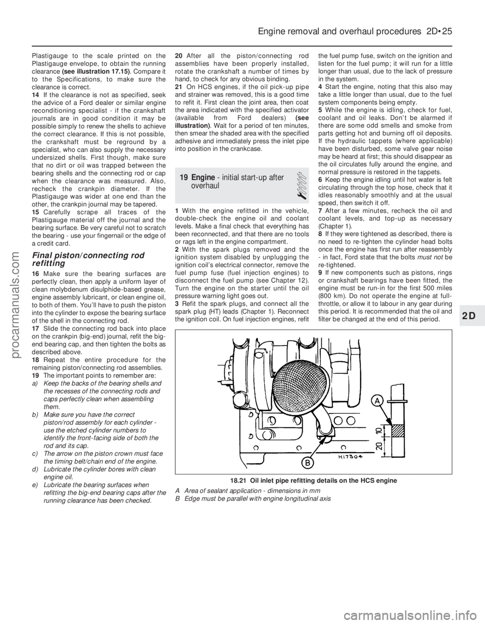
(available from Ford dealers) (see
illustration) . Wait for a period of ten minutes,
then smear the shaded area with the specified
adhesive and immediately press the inlet pipe
into position in the crankcase.
19 Engine - initial start-up after
overhaul
1
1 With the engine refitted in the vehicle,
double-check the engine oil and coolant
levels. Make a final check that everything has
been reconnected, and that there are no tools
or rags left in the engine compartment.
2 With the spark plugs removed and the
ignition system disabled by unplugging the
ignition coil’s electrical connector, remove the
fuel pump fuse (fuel injection engines) to
disconnect the fuel pump (see Chapter 12).
Turn the engine on the starter until the oil
pressure warning light goes out.
3 Refit the spark plugs, and connect all the
spark plug (HT) leads (Chapter 1). Reconnect
the ignition coil. On fuel injection engines, refit the fuel pump fuse, switch on the ignition and
listen for the fuel pump; it will run for a little
longer than usual, due to the lack of pressure
in the system.
4
Start the engine, noting that this also may
take a little longer than usual, due to the fuel
system components being empty.
5 While the engine is idling, check for fuel,
coolant and oil leaks. Don’t be alarmed if
there are some odd smells and smoke from
parts getting hot and burning off oil deposits.
If the hydraulic tappets (where applicable)
have been disturbed, some valve gear noise
may be heard at first; this should disappear as
the oil circulates fully around the engine, and
normal pressure is restored in the tappets.
6 Keep the engine idling until hot water is felt
circulating through the top hose, check that it
idles reasonably smoothly and at the usual
speed, then switch it off.
7 After a few minutes, recheck the oil and
coolant levels, and top-up as necessary
(Chapter 1).
8 If they were tightened as described, there is
no need to re-tighten the cylinder head bolts
once the engine has first run after reassembly
- in fact, Ford state that the bolts must notbe
re-tightened.
9 If new components such as pistons, rings
or crankshaft bearings have been fitted, the
engine must be run-in for the first 500 miles
(800 km). Do not operate the engine at full-
throttle, or allow it to labour in any gear during
this period. It is recommended that the oil and
filter be changed at the end of this period.
Engine removal and overhaul procedures 2D•25
18.21 Oil inlet pipe refitting details on the HCS engine
A Area of sealant application - dimensions in mm
B Edge must be parallel with engine longitudinal axis
2D
1595Ford Fiesta Remakeprocarmanuals.com
http://vnx.su
Page 100 of 296
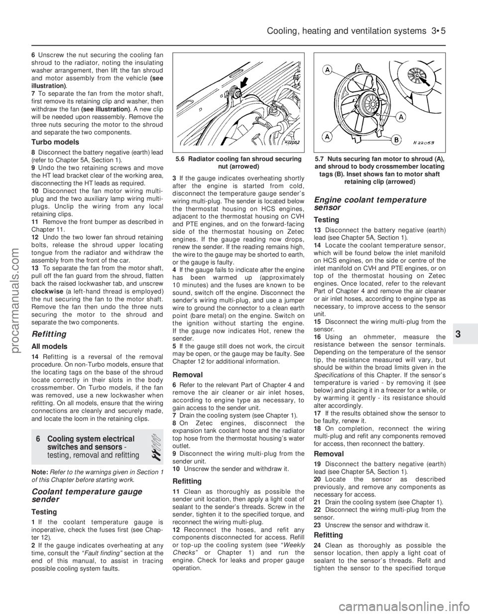
6Unscrew the nut securing the cooling fan
shroud to the radiator, noting the insulating
washer arrangement, then lift the fan shroud
and motor assembly from the vehicle (see
illustration) .
7 To separate the fan from the motor shaft,
first remove its retaining clip and washer, then
withdraw the fan (see illustration) . A new clip
will be needed upon reassembly. Remove the
three nuts securing the motor to the shroud
and separate the two components.
Turbo models
8 Disconnect the battery negative (earth) lead
(refer to Chapter 5A, Section 1).
9 Undo the two retaining screws and move
the HT lead bracket clear of the working area,
disconnecting the HT leads as required.
10 Disconnect the fan motor wiring multi-
plug and the two auxiliary lamp wiring multi-
plugs. Unclip the wiring from any local
retaining clips.
11 Remove the front bumper as described in
Chapter 11.
12 Undo the two lower fan shroud retaining
bolts, release the shroud upper locating
tongue from the radiator and withdraw the
assembly from the front of the car.
13 To separate the fan from the motor shaft,
pull off the fan guard from the shroud, flatten
back the raised lockwasher tab, and unscrew
clockwise (a left-hand thread is employed)
the nut securing the fan to the motor shaft.
Remove the fan then undo the three nuts
securing the motor to the shroud and
separate the two components.
Refitting
All models
14 Refitting is a reversal of the removal
procedure. On non-Turbo models, ensure that
the locating tags on the base of the shroud
locate correctly in their slots in the body
crossmember. On Turbo models, if the fan
was removed, use a new lockwasher when
refitting. On all models, ensure that the wiring
connections are cleanly and securely made,
and locate the loom in the retaining clips.
6 Cooling system electrical switches and sensors -
testing, removal and refitting
2
Note: Refer to the warnings given in Section 1
of this Chapter before starting work.
Coolant temperature gauge
sender
Testing
1 If the coolant temperature gauge is
inoperative, check the fuses first (see Chap-
ter 12).
2 If the gauge indicates overheating at any
time, consult the “Fault finding” section at the
end of this manual, to assist in tracing
possible cooling system faults. 3
If the gauge indicates overheating shortly
after the engine is started from cold,
disconnect the temperature gauge sender’s
wiring multi-plug. The sender is located below
the thermostat housing on HCS engines,
adjacent to the thermostat housing on CVH
and PTE engines, and on the forward-facing
side of the thermostat housing on Zetec
engines. If the gauge reading now drops,
renew the sender. If the reading remains high,
the wire to the gauge may be shorted to earth,
or the gauge is faulty.
4 If the gauge fails to indicate after the engine
has been warmed up (approximately
10 minutes) and the fuses are known to be
sound, switch off the engine. Disconnect the
sender’s wiring multi-plug, and use a jumper
wire to ground the connector to a clean earth
point (bare metal) on the engine. Switch on
the ignition without starting the engine.
If the gauge now indicates Hot, renew the
sender.
5 If the gauge still does not work, the circuit
may be open, or the gauge may be faulty. See
Chapter 12 for additional information.
Removal
6 Refer to the relevant Part of Chapter 4 and
remove the air cleaner or air inlet hoses,
according to engine type as necessary, to
gain access to the sender unit.
7 Drain the cooling system (see Chapter 1).
8 On Zetec engines, disconnect the
expansion tank coolant hose and the radiator
top hose from the thermostat housing’s water
outlet.
9 Disconnect the wiring multi-plug from the
sender unit.
10 Unscrew the sender and withdraw it.
Refitting
11Clean as thoroughly as possible the
sender unit location, then apply a light coat of
sealant to the sender’s threads. Screw in the
sender, tighten it to the specified torque, and
reconnect the wiring multi-plug.
12 Reconnect the hoses, and refit any
components disconnected for access. Refill
or top-up the cooling system (see “Weekly
Checks” or Chapter 1) and run the
engine. Check for leaks and proper gauge
operation.
Engine coolant temperature
sensor
Testing
13 Disconnect the battery negative (earth)
lead (see Chapter 5A, Section 1).
14 Locate the coolant temperature sensor,
which will be found below the inlet manifold
on HCS engines, on the side or centre of the
inlet manifold on CVH and PTE engines, or on
top of the thermostat housing on Zetec
engines. Once located, refer to the relevant
Part of Chapter 4 and remove the air cleaner
or air inlet hoses, according to engine type as
necessary, to improve access to the sensor
unit.
15 Disconnect the wiring multi-plug from the
sensor.
16 Using an ohmmeter, measure the
resistance between the sensor terminals.
Depending on the temperature of the sensor
tip, the resistance measured will vary, but
should be within the broad limits given in the
Specifications of this Chapter. If the sensor’s
temperature is varied - by removing it (see
below) and placing it in a freezer for a while, or
by warming it gently - its resistance should
alter accordingly.
17 If the results obtained show the sensor to
be faulty, renew it.
18 On completion, reconnect the wiring
multi-plug and refit any components removed
for access, then reconnect the battery.
Removal
19 Disconnect the battery negative (earth)
lead (see Chapter 5A, Section 1).
20 Locate the sensor as described
previously, and remove any components as
necessary for access.
21 Drain the cooling system (see Chapter 1).
22 Disconnect the wiring multi-plug from the
sensor.
23 Unscrew the sensor and withdraw it.
Refitting
24Clean as thoroughly as possible the
sensor location, then apply a light coat of
sealant to the sensor’s threads. Refit and
tighten the sensor to the specified torque
Cooling, heating and ventilation systems 3•5
5.7 Nuts securing fan motor to shroud (A),
and shroud to body crossmember locating tags (B). Inset shows fan to motor shaft retaining clip (arrowed)5.6 Radiator cooling fan shroud securing nut (arrowed)
3
1595Ford Fiesta Remakeprocarmanuals.com
http://vnx.su
Page 102 of 296

Refitting
23Refit in the reverse order of removal. Top-
up the cooling system as described in
“Weekly Checks”.
8 Water pump (HCS engines) -
removal and refitting
2
Note: Refer to the warnings given in Section 1
of this Chapter before starting work.
Removal
1 Disconnect the battery negative (earth) lead
(refer to Chapter 5A, Section 1).
2 Drain the cooling system (see Chapter 1).
3 Slacken the water pump pulley retaining
bolts, then remove the auxiliary drivebelt as
described in Chapter 1 (see illustration).
4 Remove the retaining bolts, and remove the
drivebelt pulley from the water pump.
5 Loosen off the coolant hose securing clips,
and disconnect the hoses from the water
pump.
6 Unscrew the retaining bolts, and withdraw
the water pump from the engine (see
illustration) .
7 No provision is made for the repair of the
water pump; if it is noisy or defective in any
way, it must be renewed.
Refitting
8 Clean all traces of gasket from the engine
and the water pump mating faces. Ensure that
the mating faces are clean and dry. Note
that the water pump gasket fitted during
production is integral with the timing cover
gasket, and this will need to be cut away
using a sharp knife, keeping as close to the
timing cover as possible.
9 Refitting is a reversal of the removal
procedure. Use a new gasket, lightly smeared
with jointing compound, and tighten the
retaining bolts to the specified torque.
10 Refit and adjust the auxiliary drivebelt as
described in Chapter 1.
11 Refill the cooling system as described in
Chapter 1, and reconnect the battery.
9 Water pump (CVH and PTE engines) -
removal and refitting
4
Note: Refer to the warnings given in Section 1
of this Chapter before starting work.
Removal
1 Disconnect the battery negative (earth) lead
(refer to Chapter 5A, Section 1).
2 Drain the cooling system (see Chapter 1).
3 Remove the timing belt and tensioner (see
Chapter 2B). If the belt is fouled with coolant,
it must be renewed as a matter of course.
4 Loosen off the coolant hose retaining clip,
and detach the coolant hose from the water
pump.
5 Unscrew and remove the four bolts
securing the water pump to the front end face
of the cylinder block, and then withdraw the
pump from the vehicle (see illustration).
Refitting
6Clean the engine water pump mating faces.
Ensure that the mating faces are clean and
dry.
7 No provision is made for the repair of the
water pump; if it is noisy or defective in any
way, it must be renewed.
8 Refitting is a reversal of the removal
procedure. Tighten the retaining bolts to the
specified torque, and ensure that the coolant
hose connection to the water pump is
securely made. 9
Refit the timing belt and tensioner as
described in Chapter 2B.
10 Refill the cooling system as described in
Chapter 1, and reconnect the battery.
10 Water pump (Zetec engines) - removal and refitting
4
Note: Refer to the warnings given in Section 1
of this Chapter before starting work.
Removal
1 Disconnect the battery negative (earth) lead
(refer to Chapter 5A, Section 1).
2 Drain the cooling system (see Chapter 1).
3 Remove the timing belt and tensioner (see
Chapter 2C). If the belt is fouled with coolant,
it must be renewed as a matter of course.
4 Disconnect the radiator bottom hose from
the pump union.
5 Unbolt and remove the water pump (see
illustrations) . If the pump is to be renewed,
unbolt the timing belt guide pulleys, and
transfer them to the new pump.
Refitting
6 Clean the mating surfaces carefully; the
gasket must be renewed whenever it is
disturbed.
7 On refitting, use grease to stick the new
gasket in place, refit the pump, and tighten
the pump bolts to the specified torque.
8 The remainder of refitting is a reversal of the
Cooling, heating and ventilation systems 3•7
9.5 CVH engine timing belt tensioner
retaining bolts (A) and water pump securing bolts (B)8.6 HCS engine water pump removal8.3 HCS engine water pump pulleyretaining bolts (arrowed)
10.5b . . . and remove the Zetec engine water pump10.5a Unscrew the bolts (arrowed) . . .
3
1595Ford Fiesta Remakeprocarmanuals.com
http://vnx.su
Page 108 of 296
1 General information andprecautions
General information
The fuel system on all models with
carburettor induction comprises a rear-
mounted fuel tank, a mechanical diaphragm
fuel pump, a carburettor and an air cleaner. The fuel tank is mounted at the rear, under
the floorpan behind the rear seats. The tank
has a “ventilation-to-atmosphere system”
through a combined roll-over/anti-trickle fill
valve assembly, located in the left-hand rear
wheel arch. A filler neck sensing pipe, integral
with the fuel tank filler pipe, will shut off the
petrol pump filler gun when the predetermined
maximum level of fuel is reached in the tank,
so preventing spillage and wastage. A
conventional fuel level sender unit is mounted
in the top face of the fuel tank. One of two fuel pump types will be fitted,
depending on the engine type. On HCS
engines, the fuel pump is operated by a
pivoting rocker arm; one end rests on an
eccentric lobe on the engine camshaft, and
the other end is attached to the fuel pump
diaphragm. The pump fitted to the CVH
engine is operated by a separate pushrod,
one end rests on an eccentric lobe on the
engine camshaft, and the other rests on the
pump actuating rod which operates the
diaphragm. Both types of mechanical pump
incorporate a nylon mesh filter, and are of
sealed type (they cannot be serviced or
overhauled). Four different types of Weber carburettor
are featured in the range, further details being
given in later Sections of this Chapter. The air cleaner incorporates a “waxstat”
controlled air inlet, supplying either hot air
from a shroud mounted around the exhaust
manifold, or cool air from a duct in the front of
the vehicle.
Precautions
Warning: Petrol is extremely
flammable - great care must be
taken when working on any part of the fuel system. Do not smoke or allow
any naked flames or uncovered light bulbs
near the work area. Note that gas powered
domestic appliances with pilot flames,
such as heaters, boilers and tumble
dryers, also present a fire hazard - bear
this in mind if you are working in an area
where such appliances are present.
Always keep a suitable fire extinguisher
close to the work area and familiarise
yourself with its operation before starting
work. Wear eye protection when working
on fuel systems and wash off any fuel spilt
on bare skin immediately with soap and
water. Note that fuel vapour is just as
dangerous as liquid fuel; a vessel that has
just been emptied of liquid fuel will still
contain vapour and can be potentially
explosive. Petrol is a highly dangerous and
volatile liquid, and the precautions
necessary when handling it cannot be
overstressed.
Many of the operations described in this
Chapter involve the disconnection of fuel
lines, which may cause an amount of fuel
spillage. Before commencing work, refer
to the above Warning and the information
in “Safety first” at the beginning of this
manual.
When working with fuel system
components, pay particular attention to
cleanliness - dirt entering the fuel system
may cause blockages which will lead to
poor running.
Certain adjustment points in the fuel system
are protected by tamperproof caps, plugs or
seals. In some territories, it is an offence to
drive a vehicle with broken or missing
tamperproof seals. Before disturbing a
tamperproof seal, first check that no local or
national laws will be broken by doing so, and
fit a new tamperproof seal after adjustment is
complete, where required by law. Do not
break tamperproof seals on any vehicle whilst
it is still under warranty. Carburettors are delicate instruments, and
care must be taken not to disturb any
components unnecessarily. Before attempting
work on a carburettor, ensure that the relevant
spares are available; it should be noted that a complete strip down of a carburettor is
unlikely to cure a fault which is not
immediately obvious, without introducing new
problems. If persistent problems occur, it is
recommended that the services of a Ford
dealer or a carburettor specialist are sought.
Most dealers will be able to provide
carburettor rejetting and servicing facilities.
Where necessary, it may be possible to
purchase a reconditioned carburettor.
2 Air cleaner
-
removal and refitting
1
Note: Air cleaner element renewal and air
cleaner temperature control system checks
are described in Chapter 1.
Removal
1 Disconnect the battery negative (earth) lead
(refer to Chapter 5A, Section 1).
2 On CVH engine models, pull free and
release the accelerator cable from the locating
clip on the side of the air cleaner.
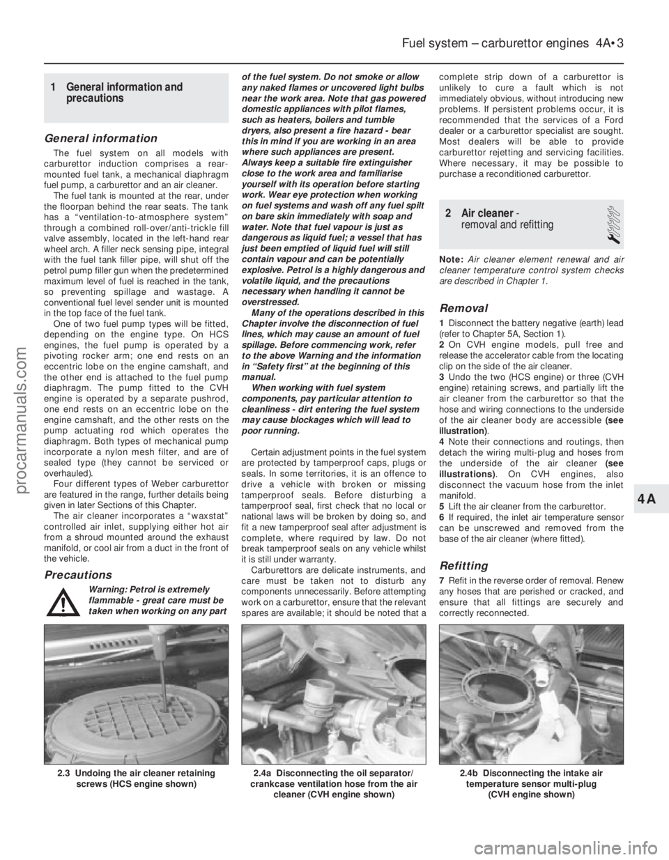
3 Undo the two (HCS engine) or three (CVH
engine) retaining screws, and partially lift the
air cleaner from the carburettor so that the
hose and wiring connections to the underside
of the air cleaner body are accessible (see
illustration) .
4 Note their connections and routings, then
detach the wiring multi-plug and hoses from
the underside of the air cleaner (see
illustrations) . On CVH engines, also
disconnect the vacuum hose from the inlet
manifold.
5 Lift the air cleaner from the carburettor.
6 If required, the inlet air temperature sensor
can be unscrewed and removed from the
base of the air cleaner (where fitted).
Refitting
7 Refit in the reverse order of removal. Renew
any hoses that are perished or cracked, and
ensure that all fittings are securely and
correctly reconnected.
Fuel system – carburettor engines 4A•3
2.4b Disconnecting the intake air temperature sensor multi-plug
(CVH engine shown)2.4a Disconnecting the oil separator/
crankcase ventilation hose from the air
cleaner (CVH engine shown)2.3 Undoing the air cleaner retainingscrews (HCS engine shown)
4A
1595Ford Fiesta Remakeprocarmanuals.com
http://vnx.su
Page 109 of 296

3Accelerator cable (manual
transmission models) -
removal, refitting and adjustment
1
Removal
1 Disconnect the battery negative (earth) lead
(refer to Chapter 5A, Section 1).
2 Working inside the vehicle, disconnect the
cable from the top of the accelerator pedal,
release the grommet and pull the cable free
from the pedal. Withdraw the cable through
the engine side of the bulkhead.
3 Refer to Section 2 and remove the air
cleaner.
4 Detach the inner cable from the carburettor
linkage.
5 Prise free the retaining clip, detach the
outer cable from the support bracket, and
remove the cable (see illustrations) .
Refitting and adjustment
6To refit the cable, feed the inner cable
through the bulkhead, and reconnect the inner
cable to the accelerator pedal. Note that a
plastic sleeve is supplied with new cables for
the purpose of routing through the bulkhead
panel.
7 Locate the grommet in the bulkhead, then
push the outer cable into it to secure it in the
bulkhead.
8 Lubricate the cable grommet at the
carburettor end with a mild soapy solution, then reconnect the cable to the carburettor.
Locate the outer cable by pulling it towards
the rocker cover.
9
Have an assistant depress the accelerator
pedal fully, and hold it in this position. The
outer cable should be seen to move in its
grommet. Refit the securing clip to the
bracket, then release the accelerator pedal.
10 Depress the accelerator pedal, then
release it and check that the throttle opens
and shuts fully. Further adjust if necessary
before refitting the air cleaner and
reconnecting the battery.
4 Accelerator cable (CTX automatic transmission
models) - adjustment
4
The system for operating the throttle-plate
in the carburettor on CTX automatic
transmission equipped vehicles is completely
different to that employed on manual
transmission vehicles. The cable from the
accelerator pedal leads to a linkage
mechanism which is bolted to the
transmission housing. Two further cables lead
from this linkage mechanism, one of which
operates the throttle-plate in the carburettor. As all three cables have to be adjusted at
the same time, and access to a Ford special
tool is required, it is recommended that a Ford
dealer be entrusted with cable adjustments,
or renewal.
5 Accelerator pedal -
removal and refitting
1
Removal
1 Disconnect the battery negative (earth) lead
(refer to Chapter 5A, Section 1).
2 Peel back the carpet and insulation from
the driver’s footwell to allow access to the
accelerator pedal.
3 Detach the accelerator cable from the pedal
(see Section 3), then release the circlip from
the pivot shaft and remove the accelerator
pedal.
Refitting
4 Refit in the reverse order of removal. On
completion, check the action of the pedal and
the cable to ensure that the throttle has full
unrestricted movement, and fully returns
when released.
5 Reconnect the battery negative lead.
6 Choke cable - removal,
refitting and adjustment
1
Removal
1 Disconnect the battery negative (earth) lead
(refer to Chapter 5A, Section 1).
2 Refer to Section 2 and remove the air
cleaner.
3 Referring to Chapter 10, Section 20, for
further details and illustrations, remove the
choke control knob on the side of the steering
column shroud by pushing in the pin located
on the side of the knob and withdrawing.
4 Detach the steering column lower shroud,
disconnect the multi-plug from the choke
warning light switch/pull control assembly,
and unscrew the collar securing the
switch/pull control assembly to the shroud.
5 Disconnect the choke inner cable from its
location on the carburettor choke linkage,
then release the outer cable retaining clip (see
illustrations) .
6 Push the bulkhead panel grommet through
the bulkhead and remove the cable.
Refitting
7 Route the cable through the bulkhead then
secure the bulkhead panel grommet to its
location.
8 Reconnect the choke inner cable to its
location on the carburettor choke linkage.
9 Refit the choke warning light switch/pull
control assembly to the lower steering column
shroud and secure with the collar, then
reconnect the multi-plug.
10 Refit and secure the lower steering
column shroud, then refit the choke control
knob.
11 Pull the choke control knob to the fully-on
position. Hold the choke in the fully-on
4A•4 Fuel system – carburettor engines
6.5b Choke outer cable retaining clip
released6.5a Disconnect the inner cable from thechoke linkage
3.5b . . . then release from its support bracket3.5a Remove the accelerator outer cablesecuring clip . . .
1595Ford Fiesta Remakeprocarmanuals.com
http://vnx.su
Page 110 of 296
position at the carburettor, then secure the
outer cable with its retaining clip.
Adjustment
12To check that the choke cable is correctly
adjusted, the control knob must be pulled out
to the full-on position and the choke lever
must be in contact with its stop. Adjust as
required if necessary.
13 Press the choke knob fully in (to the off
position), then check that the choke linkage at
the carburettor has fully returned to its off
position and the choke valve plate in the
carburettor is at a right angle (90º) to the
venturi.
14 Refit the air cleaner.
15 Reconnect the battery, turn the ignition
on, operate the choke and check that the
choke warning light operates correctly.
7 Fuel pump -
testing, removal and refitting
2
Note: Refer to the warning note in Section 1
before proceeding.
Testing
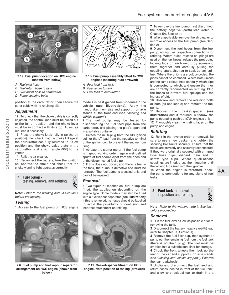
1 Access to the fuel pump on HCS engine models is best gained from underneath the
vehicle
(see illustrations) . Apply the
handbrake, then raise and support it on axle
stands at the front end (see “Jacking and
vehicle support” ).
2 The fuel pump may be tested by
disconnecting the fuel feed pipe from the
carburettor, and placing the pipe’s open end
in a suitable container.
3 Detach the multi-plug from the DIS ignition
coil, or the LT lead from the negative terminal
of the ignition coil, to prevent the engine from
firing.
4 Actuate the starter motor. If the fuel pump
is in good working order, regular well-defined
spurts of fuel should eject from the open end
of the disconnected fuel pipe.
5 If this does not occur, and there is fuel in
the tank, the pump is defective and must be
renewed. The fuel pump is a sealed unit, and
cannot be repaired.
Removal
6 Two types of mechanical fuel pump are
fitted, the application depending on the
engine type. Some models may also be fitted
with a fuel vapour separator (see illustration) ;
if this is removed, its hoses should be labelled
to avoid the possibility of confusion and
incorrect attachment on refitting. 7
To remove the fuel pump, first disconnect
the battery negative (earth) lead (refer to
Chapter 5A, Section 1).
8 Where applicable, remove the air cleaner to
improve access to the fuel pump (see Sec-
tion 2).
9 Disconnect the fuel hoses from the fuel
pump, noting their respective connections for
refitting. Where quick-release couplings are
used on the fuel hoses, release the protruding
locking lugs on each union, by squeezing
them together and carefully pulling the
coupling apart. Use rag to soak up any spilt
fuel. Where the unions are colour-coded, the
pipes cannot be confused. Where both unions
are the same colour, note carefully which pipe
is connected to which, and ensure that they
are correctly reconnected on refitting. Plug
the hoses to prevent fuel spillage and the
ingress of dirt.
10 Unscrew and remove the retaining bolts
or nuts (as applicable) and remove the fuel
pump.
11 Recover the gasket/spacer (see
illustration) and if required, withdraw the
pump operating pushrod (CVH engines only).
12 Thoroughly clean the mating faces on the
pump and engine.
Refitting
13 Refit in the reverse order of removal. Be
sure to use a new gasket, and tighten the
securing bolts/nuts securely. Ensure that the
hoses are correctly and securely reconnected.
If they were originally secured with crimped
type hose clips, discard them and fit
screw type clips. Where quick-release
couplings are fitted, press them together until
the locking lugs snap into their groove.
14 When the engine is restarted, check
the pump connections for any signs of fuel
leaks.
8 Fuel tank - removal,
inspection and refitting
3
Note: Refer to the warning note in Section 1
before proceeding.
Removal
1 Run the fuel level as low as possible prior to
removing the tank.
2 Disconnect the battery negative (earth) lead
(refer to Chapter 5A, Section 1).
3 Remove the fuel filler cap, then syphon or
pump out the remaining fuel from the fuel tank
(there is no drain plug). The fuel must be
emptied into a suitable container for storage.
4 Chock the front wheels then jack up the
rear of the car and support it on axle stands
(see “Jacking and vehicle support” ). Remove
the rear roadwheels.
5 Unclip and disconnect the fuel feed and
return hoses located in front of the fuel tank,
and allow any residual fuel to drain into a
Fuel system – carburettor engines 4A•5
7.6 Fuel pump and fuel vapour separator
arrangement on HCS engine (shown from
below)
7.1b Fuel pump assembly fitted to CVHengines (securing nuts arrowed)
A Fuel feed from tank
B Fuel return to tank
C Fuel feed to carburettor7.1a Fuel pump location on HCS engine (shown from below)
A Fuel inlet hose
B Fuel return hose to tank
C Fuel outlet hose to carburettor
D Pump securing bolts
7.11 Gasket/spacer fitment on HCS
engine. Note position of the lug (arrowed)
4A
1595Ford Fiesta Remakeprocarmanuals.com
http://vnx.su
Page 111 of 296
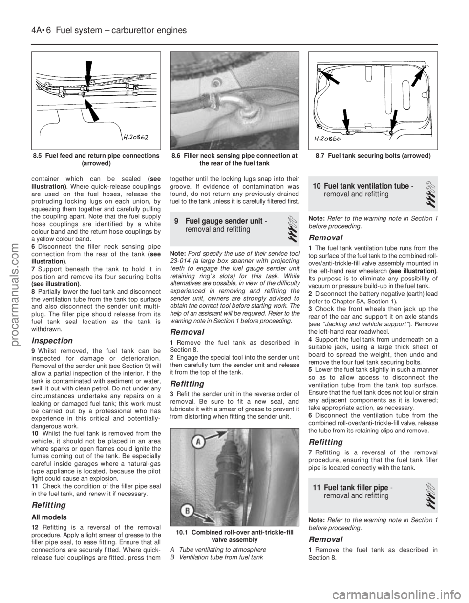
container which can be sealed (see
illustration) . Where quick-release couplings
are used on the fuel hoses, release the
protruding locking lugs on each union, by
squeezing them together and carefully pulling
the coupling apart. Note that the fuel supply
hose couplings are identified by a white
colour band and the return hose couplings by
a yellow colour band.
6 Disconnect the filler neck sensing pipe
connection from the rear of the tank (see
illustration) .
7 Support beneath the tank to hold it in
position and remove its four securing bolts
(see illustration) .
8 Partially lower the fuel tank and disconnect
the ventilation tube from the tank top surface
and also disconnect the sender unit multi-
plug. The filler pipe should release from its
fuel tank seal location as the tank is
withdrawn.
Inspection
9 Whilst removed, the fuel tank can be
inspected for damage or deterioration.
Removal of the sender unit (see Section 9) will
allow a partial inspection of the interior. If the
tank is contaminated with sediment or water,
swill it out with clean petrol. Do not under any
circumstances undertake any repairs on a
leaking or damaged fuel tank; this work must
be carried out by a professional who has
experience in this critical and potentially-
dangerous work.
10 Whilst the fuel tank is removed from the
vehicle, it should not be placed in an area
where sparks or open flames could ignite the
fumes coming out of the tank. Be especially
careful inside garages where a natural-gas
type appliance is located, because the pilot
light could cause an explosion.
11 Check the condition of the filler pipe seal
in the fuel tank, and renew it if necessary.
Refitting
All models
12 Refitting is a reversal of the removal
procedure. Apply a light smear of grease to the
filler pipe seal, to ease fitting. Ensure that all
connections are securely fitted. Where quick-
release fuel couplings are fitted, press them together until the locking lugs snap into their
groove. If evidence of contamination was
found, do not return any previously-drained
fuel to the tank unless it is carefully filtered first.
9
Fuel gauge sender unit -
removal and refitting
3
Note: Ford specify the use of their service tool
23-014 (a large box spanner with projecting
teeth to engage the fuel gauge sender unit
retaining ring’s slots) for this task. While
alternatives are possible, in view of the difficulty
experienced in removing and refitting the
sender unit, owners are strongly advised to
obtain the correct tool before starting work. The
help of an assistant will be required. Refer to the
warning note in Section 1 before proceeding.
Removal
1 Remove the fuel tank as described in
Section 8.
2 Engage the special tool into the sender unit
then carefully turn the sender unit and release
it from the top of the tank.
Refitting
3 Refit the sender unit in the reverse order of
removal. Be sure to fit a new seal, and
lubricate it with a smear of grease to prevent it
from distorting when fitting the sender unit.
10 Fuel tank ventilation tube -
removal and refitting
3
Note: Refer to the warning note in Section 1
before proceeding.
Removal
1 The fuel tank ventilation tube runs from the
top surface of the fuel tank to the combined roll-
over/anti-trickle-fill valve assembly mounted in
the left-hand rear wheelarch (see illustration).
Its purpose is to eliminate any possibility of
vacuum or pressure build-up in the fuel tank.
2 Disconnect the battery negative (earth) lead
(refer to Chapter 5A, Section 1).
3 Chock the front wheels then jack up the
rear of the car and support it on axle stands
(see “Jacking and vehicle support” ). Remove
the left-hand rear roadwheel.
4 Support the fuel tank from underneath on a
suitable jack, using a large thick sheet of
board to spread the weight, then undo and
remove the four fuel tank securing bolts.
5 Lower the fuel tank slightly in such a manner
so as to allow access to disconnect the
ventilation tube from the tank top surface.
Ensure that the fuel tank does not foul or strain
any adjacent components as it is lowered;
take appropriate action, as necessary.
6 Disconnect the ventilation tube from the
combined roll-over/anti-trickle-fill valve, release
the tube from its retaining clips and remove.
Refitting
7 Refitting is a reversal of the removal
procedure, ensuring that the fuel tank filler
pipe is located correctly with the tank.
11 Fuel tank filler pipe -
removal and refitting
3
Note: Refer to the warning note in Section 1
before proceeding.
Removal
1 Remove the fuel tank as described in
Section 8.
4A•6 Fuel system – carburettor engines
10.1 Combined roll-over anti-trickle-fill valve assembly
A Tube ventilating to atmosphere
B Ventilation tube from fuel tank
8.7 Fuel tank securing bolts (arrowed)8.6 Filler neck sensing pipe connection at the rear of the fuel tank
1595Ford Fiesta Remake
8.5 Fuel feed and return pipe connections
(arrowed)procarmanuals.com
http://vnx.su
Page 112 of 296
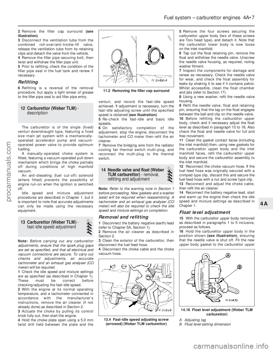
2Remove the filler cap surround (see
illustration) .
3 Disconnect the ventilation tube from the
combined roll-over/anti-trickle-fill valve,
release the ventilation tube from its retaining
clips and detach the valve from the vehicle.
4 Remove the filler pipe securing bolt, then
twist and withdraw the filler pipe unit.
5 Prior to refitting, check the condition of the
filler pipe seal in the fuel tank and renew if
necessary.
Refitting
6 Refitting is a reversal of the removal
procedure, but apply a light smear of grease
to the filler pipe seal to aid filler pipe entry.
12 Carburettor (Weber TLM) -
description
The carburettor is of the single (fixed)
venturi downdraught type, featuring a fixed
size main jet system with a mechanically-
operated accelerator pump and vacuum-
operated power valve to provide optimum
fuelling. A manually-operated choke system is
fitted, featuring a vacuum-operated pull-down
mechanism which brings the choke partially
off during conditions of high manifold
vacuum. An anti-dieseling (fuel cut-off) solenoid
(where fitted) prevents the possibility of
engine run-on when the ignition is switched
off. Idle speed and mixture adjustment
procedures are described in Chapter 1, but it
is important to note that accurate adjustments
can only be made using the necessary
equipment.
13 Carburettor (Weber TLM) -
fast-idle speed adjustment
4
Note: Before carrying out any carburettor
adjustments, ensure that the spark plug gaps
are set as specified, and that all electrical and
vacuum connections are secure. To carry out
checks and adjustments, an accurate
tachometer and an exhaust gas analyser (CO
meter) will be required.
1 Check the idle speed and mixture settings
are as specified (as described in Chapter 1).
These must be correct before
checking/adjusting the fast-idle speed.
2 With the engine at its normal operating
temperature, and a tachometer connected in
accordance with the manufacturer’s
instructions, remove the air cleaner (if not
already done) as described in Section 2.
3 Actuate the choke by pulling its control
knob fully out, then start the engine.
4 Hold the choke plate open using a 5.0 mm
twist drill held between the plate and the venturi, and record the fast-idle speed
achieved. If adjustment is necessary, turn the
fast-idle adjusting screw until the specified
speed is obtained
(see illustration).
5 Re-check the fast-idle and basic idle
speeds.
6 On satisfactory completion of the
adjustment, stop the engine, disconnect the
tachometer and CO meter then refit the air
cleaner.
7 Remove the bridging wire from the radiator
cooling fan thermal switch multi-plug, and
reconnect the multi-plug to the thermal
switch.
14 Needle valve and float (Weber
TLM carburettor) - removal,
refitting and adjustment
4
Note: Refer to the warning note in Section 1
before proceeding. New gaskets and a washer
(seal) will be required when reassembling. A
tachometer and an exhaust gas analyser (CO
meter) will also be required to check the idle
speed and mixture settings on completion.
Removal and refitting
1 Disconnect the battery negative (earth) lead
(refer to Chapter 5A, Section 1).
2 Remove the air cleaner as described in
Section 2.
3 Clean the exterior of the carburettor, then
disconnect the fuel feed hose.
4 Disconnect the choke cable and the choke
vacuum hose. 5
Remove the four screws securing the
carburettor upper body (two of these screws
are Torx head type), and detach it. Note that
the carburettor lower body is now loose
on the inlet manifold.
6 Tap out the float retaining pin, remove the
float and withdraw the needle valve. Unscrew
the needle valve housing, as required, noting
washer fitment.
7 Inspect the components for damage and
renew as necessary. Check the needle valve
for wear, and check the float assembly for
leaks by shaking it to see if it contains petrol.
Whilst accessible, clean the float chamber
and jets (refer to Section 17).
8 Using a new washer, refit the needle valve
housing.
9 Refit the needle valve, float and retaining
pin, ensuring that the tag on the float engages
between the ball and clip on the needle valve.
10 Before refitting the carburettor upper
body, check and if necessary adjust the float
level as described in paragraph 15 to 18. Also
check the float and needle valve for full and
free movement.
11 Clean the gasket contact faces (including
the inlet manifold) then, using new gaskets for
the carburettor upper body and the inlet
manifold faces, refit the carburettor upper
body and secure the carburettor assembly to
the inlet manifold.
12 Reconnect the choke vacuum hose. If the
fuel feed hose was originally secured with a
crimped type clip, discard this and secure the
fuel feed hose with a nut and screw type clip.
13 Reconnect and adjust the choke cable,
then refit the air cleaner.
14 Reconnect the battery negative lead, start
and warm up the engine then check the idle
speed and mixture settings as described in
Chapter 1.
Float level adjustment
15 With the carburettor upper body removed
as described in paragraphs 1 to 5 inclusive,
proceed as follows.
16 Hold the carburettor upper body in the
position shown (see illustration) , ensuring
that the needle valve is shut off. Fit the new
upper body gasket to the carburettor upper
Fuel system – carburettor engines 4A•7
13.4 Fast-idle speed adjusting screw (arrowed) (Weber TLM carburettor)
11.2 Removing the filler cap surround
14.16 Float level adjustment (Weber TLM carburettor)
A Adjusting tag
B Float level setting dimension
4A
1595Ford Fiesta Remakeprocarmanuals.com
http://vnx.su
Page 115 of 296
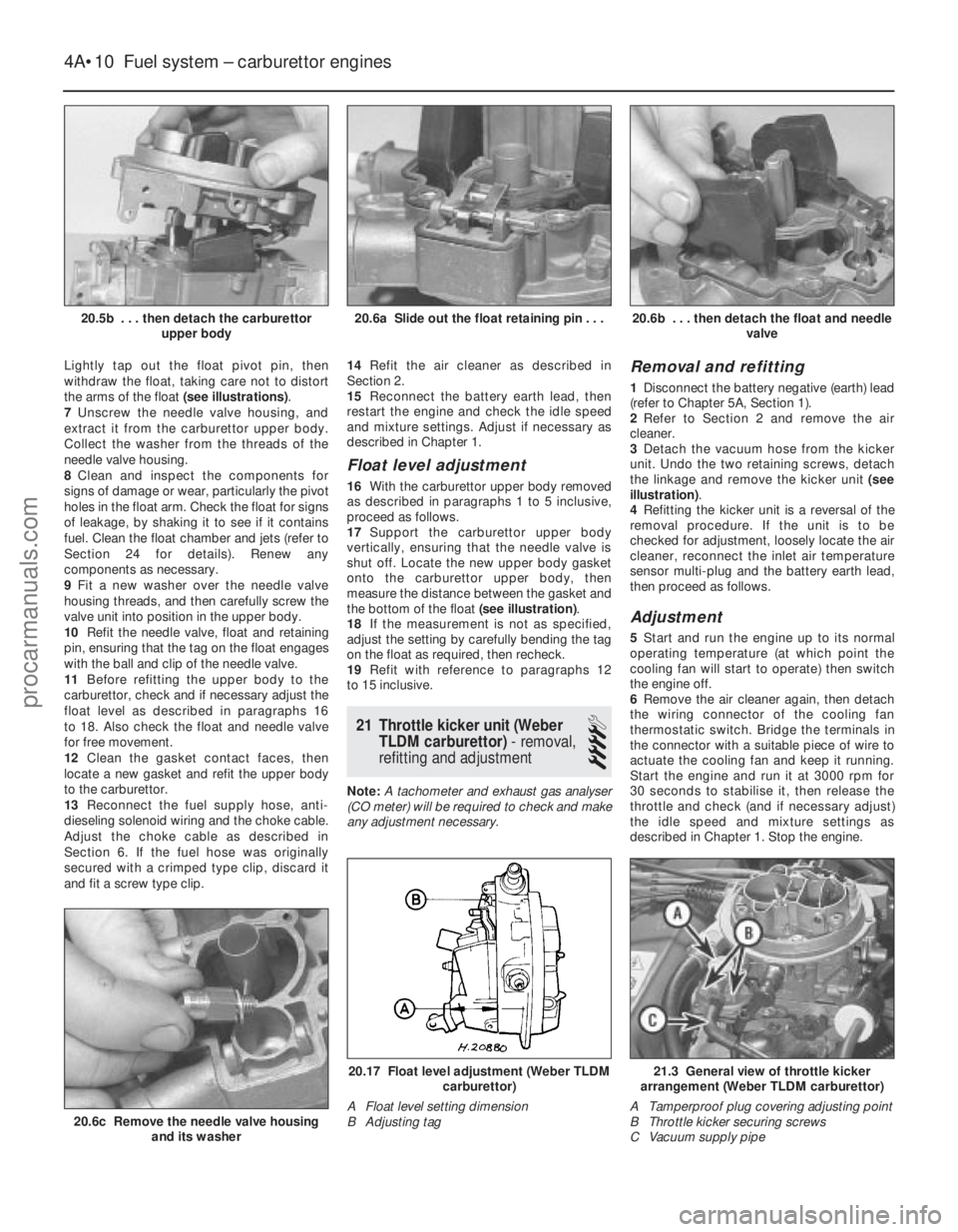
Lightly tap out the float pivot pin, then
withdraw the float, taking care not to distort
the arms of the float (see illustrations).
7 Unscrew the needle valve housing, and
extract it from the carburettor upper body.
Collect the washer from the threads of the
needle valve housing.
8 Clean and inspect the components for
signs of damage or wear, particularly the pivot
holes in the float arm. Check the float for signs
of leakage, by shaking it to see if it contains
fuel. Clean the float chamber and jets (refer to
Section 24 for details). Renew any
components as necessary.
9 Fit a new washer over the needle valve
housing threads, and then carefully screw the
valve unit into position in the upper body.
10 Refit the needle valve, float and retaining
pin, ensuring that the tag on the float engages
with the ball and clip of the needle valve.
11 Before refitting the upper body to the
carburettor, check and if necessary adjust the
float level as described in paragraphs 16
to 18. Also check the float and needle valve
for free movement.
12 Clean the gasket contact faces, then
locate a new gasket and refit the upper body
to the carburettor.
13 Reconnect the fuel supply hose, anti-
dieseling solenoid wiring and the choke cable.
Adjust the choke cable as described in
Section 6. If the fuel hose was originally
secured with a crimped type clip, discard it
and fit a screw type clip. 14
Refit the air cleaner as described in
Section 2.
15 Reconnect the battery earth lead, then
restart the engine and check the idle speed
and mixture settings. Adjust if necessary as
described in Chapter 1.
Float level adjustment
16 With the carburettor upper body removed
as described in paragraphs 1 to 5 inclusive,
proceed as follows.
17 Support the carburettor upper body
vertically, ensuring that the needle valve is
shut off. Locate the new upper body gasket
onto the carburettor upper body, then
measure the distance between the gasket and
the bottom of the float (see illustration).
18 If the measurement is not as specified,
adjust the setting by carefully bending the tag
on the float as required, then recheck.
19 Refit with reference to paragraphs 12
to 15 inclusive.
21 Throttle kicker unit (Weber TLDM carburettor) - removal,
refitting and adjustment
4
Note: A tachometer and exhaust gas analyser
(CO meter) will be required to check and make
any adjustment necessary.
Removal and refitting
1 Disconnect the battery negative (earth) lead
(refer to Chapter 5A, Section 1).
2 Refer to Section 2 and remove the air
cleaner.
3 Detach the vacuum hose from the kicker
unit. Undo the two retaining screws, detach
the linkage and remove the kicker unit (see
illustration) .
4 Refitting the kicker unit is a reversal of the
removal procedure. If the unit is to be
checked for adjustment, loosely locate the air
cleaner, reconnect the inlet air temperature
sensor multi-plug and the battery earth lead,
then proceed as follows.
Adjustment
5 Start and run the engine up to its normal
operating temperature (at which point the
cooling fan will start to operate) then switch
the engine off.
6 Remove the air cleaner again, then detach
the wiring connector of the cooling fan
thermostatic switch. Bridge the terminals in
the connector with a suitable piece of wire to
actuate the cooling fan and keep it running.
Start the engine and run it at 3000 rpm for
30 seconds to stabilise it, then release the
throttle and check (and if necessary adjust)
the idle speed and mixture settings as
described in Chapter 1. Stop the engine.
4A•10 Fuel system – carburettor engines
21.3 General view of throttle kicker
arrangement (Weber TLDM carburettor)
A Tamperproof plug covering adjusting point
B Throttle kicker securing screws
C Vacuum supply pipe20.17 Float level adjustment (Weber TLDM carburettor)
A Float level setting dimension
B Adjusting tag
20.6c Remove the needle valve housing and its washer
20.6b . . . then detach the float and needle valve20.6a Slide out the float retaining pin . . .20.5b . . . then detach the carburettorupper body
1595Ford Fiesta Remakeprocarmanuals.com
http://vnx.su
Page 126 of 296
This is used to refine the calculations made by
the module, when determining the correct
amount of fuel required to achieve the ideal
air/fuel mixture ratio.A throttle position sensor is mounted on the
end of the throttle valve spindle, to provide
the EEC IV module with a constantly-varying
(analogue) voltage signal corresponding to the
throttle opening. This allows the module to
register the driver’s input when determining
the amount of fuel required by the engine. Road speed is monitored by the vehicle
speed sensor. This component is a Hall-effect
generator, mounted on the transmission’s
speedometer drive. It supplies the EEC IV
module with a series of pulses corresponding
to the vehicle’s road speed, enabling the
module to control features such as the fuel
shut-off on overrun. A manifold absolute pressure sensor
measures inlet manifold vacuum, and supplies
this information to the module for calculation
of engine load at any given throttle position. Where power steering is fitted, a pressure-
operated switch is screwed into the power
steering system’s high-pressure pipe. The
switch sends a signal to the EEC IV module to
reduce engine speed should the power
steering fluid pressure become excessively
high. Certain later engines may be fitted with a
heater in the inlet manifold. This is controlled
by the EEC IV module to ensure that, even
before the effect of the coolant heating
becomes apparent, the manifold is warmed-
up. This prevents fuel droplets condensing in
the manifold, thus improving driveability and
reducing exhaust emissions when the engine
is cold.
The oxygen sensor in the exhaust system
provides the EEC IV module with constant
feedback - “closed-loop” control - which
enables it to adjust the mixture to provide the
best possible conditions for the catalytic
converter to operate.
Precautions
Warning: Petrol is extremely
flammable - great care must be
taken when working on any part
of the fuel system. Do not
smoke or allow any naked flames or
uncovered light bulbs near the work area.
Note that gas powered domestic
appliances with pilot flames, such as
heaters, boilers and tumble dryers, also
present a fire hazard - bear this in mind if
you are working in an area where such
appliances are present. Always keep a
suitable fire extinguisher close to the work
area and familiarise yourself with its
operation before starting work. Wear eye
protection when working on fuel systems
and wash off any fuel spilt on bare skin
immediately with soap and water. Note
that fuel vapour is just as dangerous as
liquid fuel; a vessel that has just been
emptied of liquid fuel will still contain vapour and can be potentially explosive.
Petrol is a highly dangerous and volatile
liquid, and the precautions necessary
when handling it cannot be overstressed.
Many of the operations described in this
Chapter involve the disconnection of fuel
lines, which may cause an amount of fuel
spillage. Before commencing work, refer
to the above Warning and the information
in “Safety first” at the beginning of this
manual. When working with fuel system
components, pay particular attention to
cleanliness - dirt entering the fuel system
may cause blockages which will lead to
poor running.
Note: Residual pressure will remain in the fuel
lines long after the vehicle was last used,
when disconnecting any fuel line, it will be
necessary to depressurise the fuel system as
described in Section 2 .
2 Fuel system-
depressurisation
1
Note: Refer to the warning note in Section 1
before proceeding.
Warning: The following
procedure will merely relieve the
pressure in the fuel system -
remember that fuel will still be present in
the system components, and take
precautions accordingly before
disconnecting any of them.
1 The fuel system referred to in this Chapter
is defined as the fuel tank and tank-mounted
fuel pump/fuel gauge sender unit, the fuel
filter, the fuel injector, fuel pressure regulator,
and the metal pipes and flexible hoses of the
fuel lines between these components. All
these contain fuel, which will be under
pressure while the engine is running and/or
while the ignition is switched on.
2 The pressure will remain for some time after
the ignition has been switched off, and must
be relieved before any of these components is
disturbed for servicing work.
3 The simplest depressurisation method is to
disconnect the fuel pump electrical supply by
removing the fuel pump fuse (No 19) and
starting the engine; allow the engine to idle
until it dies through lack of fuel pressure. Turn
the engine over once or twice on the starter to
ensure that all pressure is released, then
switch off the ignition; do not forget to refit the
fuse when work is complete.
4 Note that, once the fuel system has been
depressurised and drained (even partially), it
will take significantly longer to restart the
engine - perhaps several seconds of cranking
- before the system is refilled and pressure
restored.
3 Fuel lines and fittings -
general information
Note: Refer to the warning note in Section 1
before proceeding.
Disconnecting and connecting
quick-release couplings
1 Quick-release couplings are employed at
many of the unions in the fuel feed and return
lines.
2 Before disconnecting any fuel system
component, relieve the residual pressure in
the system (see Section 2), and equalise tank
pressure by removing the fuel filler cap.
Warning: This procedure will
merely relieve the increased
pressure necessary for the
engine to run - remember that
fuel will still be present in the system
components, and take precautions
accordingly before disconnecting any of
them.
3 Release the protruding locking lugs on each
union, by squeezing them together and
carefully pulling the coupling apart. Use rag to
soak up any spilt fuel. Where the unions are
colour-coded, the pipes cannot be confused.
Where both unions are the same colour, note
carefully which pipe is connected to which,
and ensure that they are correctly
reconnected on refitting.
4 To reconnect one of these couplings, press
them together until the locking lugs snap into
their groove. Switch the ignition on and off
five times to pressurise the system, and check
for any sign of fuel leakage around the
disturbed coupling before attempting to start
the engine.
Checking
5 Checking procedures for the fuel lines are
included in Chapter 1.
Component renewal
6 If any damaged sections are to be renewed,
use original-equipment replacement hoses or
pipes, constructed from exactly the same
material as the section being replaced. Do not
install substitutes constructed from inferior or
inappropriate material; this could cause a fuel
leak or a fire.
7 Before detaching or disconnecting any part
of the fuel system, note the routing of all
hoses and pipes, and the orientation of all
clamps and clips. Replacement sections must
be installed in exactly the same manner.
8 Before disconnecting any part of the fuel
system, be sure to relieve the fuel system
pressure (see Section 2), and equalise tank
pressure by removing the fuel filler cap. Also
disconnect the battery negative (earth) lead -
see Chapter 5A, Section 1. Cover the fitting
being disconnected with a rag, to absorb any
fuel that may spray out.
Fuel system - central fuel injection engines 4B•3
4B
1595Ford Fiesta Remakeprocarmanuals.com
http://vnx.su