fuel cap release FORD FIESTA 1989 Service Repair Manual
[x] Cancel search | Manufacturer: FORD, Model Year: 1989, Model line: FIESTA, Model: FORD FIESTA 1989Pages: 296, PDF Size: 10.65 MB
Page 3 of 296
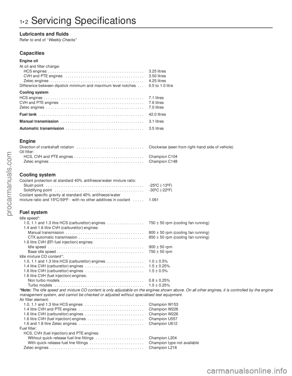
Lubricants and fluids
Refer to end of “Weekly Checks”
Capacities
Engine oil
At oil and filter change:HCS engines . . . . . . . . . . . . . . . . . . . . . . . . . . . . . . . . . . . .\
. . . . . . . . 3.25 litres
CVH and PTE engines . . . . . . . . . . . . . . . . . . . . . . . . . . . . . . . . . . . .\
3.50 litresZetec engines . . . . . . . . . . . . . . . . . . . . . . . . . . . . . . . . . . . .\
. . . . . . . 4.25 litres
Difference between dipstick minimum and maximum level notches . . . 0.5 to 1.0 litre
Cooling system
HCS engines . . . . . . . . . . . . . . . . . . . . . . . . . . . . . . . . . . . .\
. . . . . . . . . . 7.1 litresCVH and PTE engines . . . . . . . . . . . . . . . . . . . . . . . . . . . . . . . . . . . .\
. . 7.6 litresZetec engines . . . . . . . . . . . . . . . . . . . . . . . . . . . . . . . . . . . .\
. . . . . . . . . 7.0 litres
Fuel tank . . . . . . . . . . . . . . . . . . . . . . . . . . . . . . . . . . . .\
. . . . . . . . . . . . 42.0 litres
Manual transmission . . . . . . . . . . . . . . . . . . . . . . . . . . . . . . . . . . . .\
. . 3.1 litres
Automatic transmission . . . . . . . . . . . . . . . . . . . . . . . . . . . . . . . . . . . .\
3.5 litres
Engine
Direction of crankshaft rotation . . . . . . . . . . . . . . . . . . . . . . . . . . . . . . . Clockwise (seen from right-hand side of vehicle)
Oil filter: HCS, CVH and PTE engines . . . . . . . . . . . . . . . . . . . . . . . . . . . . . . . . Champion C104
Zetec engines . . . . . . . . . . . . . . . . . . . . . . . . . . . . . . . . . . . .\
. . . . . . . Champion C148
Cooling system
Coolant protection at standard 40% antifreeze/water mixture ratio:Slush point . . . . . . . . . . . . . . . . . . . . . . . . . . . . . . . . . . . .\
. . . . . . . . . -25ºC (-13ºF)Solidifying point . . . . . . . . . . . . . . . . . . . . . . . . . . . . . . . . . . . .\
. . . . . -30ºC (-22ºF)
Coolant specific gravity at standard 40% antifreeze/water
mixture ratio and 15ºC/59ºF - with no other additives in coolant . . . . . 1.061
Fuel system
Idle speed*: 1.0, 1.1 and 1.3 litre HCS (carburettor) engines . . . . . . . . . . . . . . . . . 750 ± 50 rpm (cooling fan running)
1.4 and 1.6 litre CVH (carburettor) engines:
Manual transmission . . . . . . . . . . . . . . . . . . . . . . . . . . . . . . . . . . . .\
800 ± 50 rpm (cooling fan running)CTX automatic transmission . . . . . . . . . . . . . . . . . . . . . . . . . . . . . . 850 ± 50 rpm (cooling fan running)
1.6 litre CVH (EFi fuel injection) engines: Idle speed . . . . . . . . . . . . . . . . . . . . . . . . . . . . . . . . . . . .\
. . . . . . . . 900 ± 50 rpmBase idle speed . . . . . . . . . . . . . . . . . . . . . . . . . . . . . . . . . . . .\
. . . . 750 ± 50 rpm
Idle mixture CO content*: 1.0, 1.1 and 1.3 litre HCS (carburettor) engines . . . . . . . . . . . . . . . . . 1.0 ± 0.5%
1.4 litre CVH (carburettor) engines . . . . . . . . . . . . . . . . . . . . . . . . . . . 1.5 ± 0.25%
1.6 litre CVH (carburettor) engines . . . . . . . . . . . . . . . . . . . . . . . . . . . 1.5 ± 0.5%
1.6 litre CVH (fuel injection) engines:Non turbo models . . . . . . . . . . . . . . . . . . . . . . . . . . . . . . . . . . . .\
. . 0.8 ± 0.25%
Turbo models . . . . . . . . . . . . . . . . . . . . . . . . . . . . . . . . . . . .\
. . . . . 1.5 ± 0.25%
*Note: The idle speed and mixture CO content is only adjustable on the engines \
shown above. On all other engines, it is controlled by the engine
management system, and cannot be checked or adjusted without specialised\
test equipment.
Air filter element: 1.0, 1.1 and 1.3 litre HCS engines . . . . . . . . . . . . . . . . . . . . . . . . . . . Champion W153
1.4 litre CVH and PTE engines . . . . . . . . . . . . . . . . . . . . . . . . . . . . . . Champion W226
1.6 litre CVH (carburettor) engines . . . . . . . . . . . . . . . . . . . . . . . . . . . Champion W226
1.6 litre CVH (fuel injection) engines . . . . . . . . . . . . . . . . . . . . . . . . . . Champion U557
1.6 and 1.8 litre Zetec engines . . . . . . . . . . . . . . . . . . . . . . . . . . . . . . Champion U612
Fuel filter:
HCS, CVH (fuel injection) and PTE engines:Without quick-release fuel line fittings . . . . . . . . . . . . . . . . . . . . . . Champion L204
With quick-release fuel line fittings . . . . . . . . . . . . . . . . . . . . . . . . . Champion type not available
Zetec engines . . . . . . . . . . . . . . . . . . . . . . . . . . . . . . . . . . . .\
. . . . . . . Champion L218
1•2Servicing Specifications
1595Ford Fiesta Remakeprocarmanuals.com
http://vnx.su
Page 7 of 296
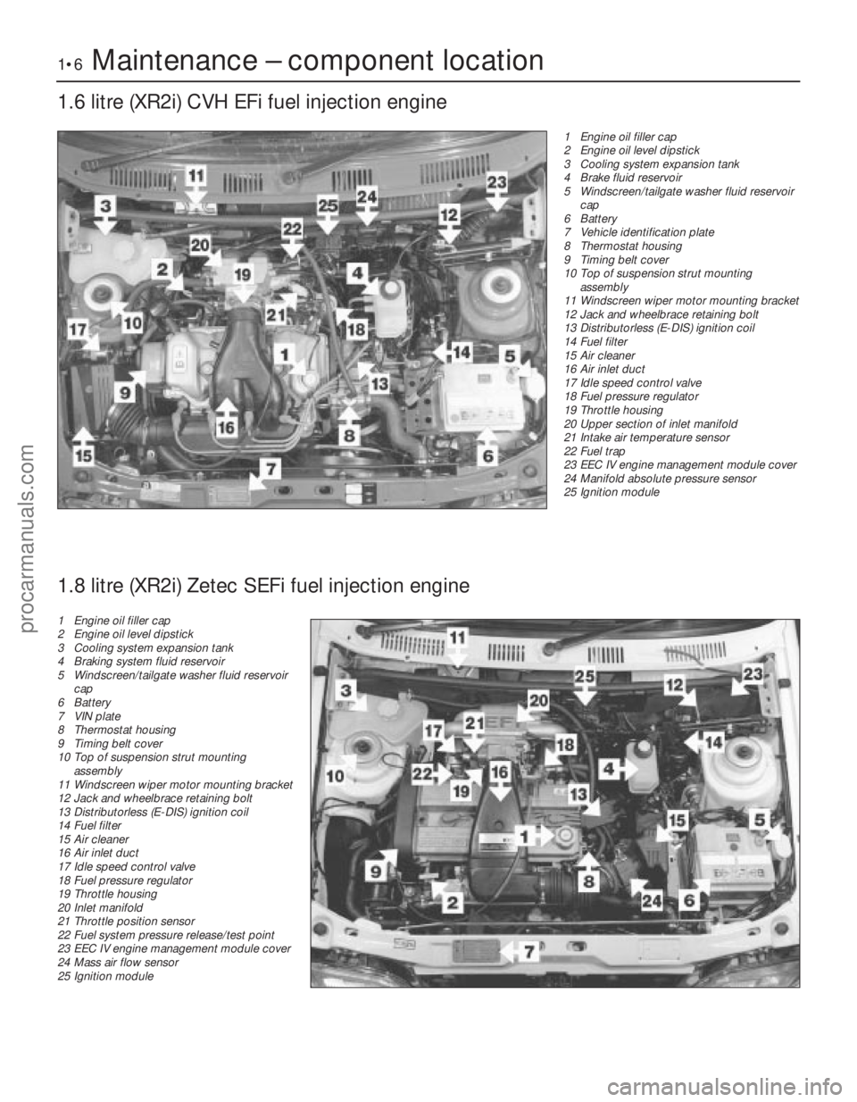
1•6Maintenance – component location
1.6 litre (XR2i) CVH EFi fuel injection engine
1595Ford Fiesta Remake1 Engine oil filler cap
2 Engine oil level dipstick
3 Cooling system expansion tank
4 Brake fluid reservoir
5 Windscreen/tailgate washer fluid reservoir
cap
6 Battery
7 Vehicle identification plate
8 Thermostat housing
9 Timing belt cover
10 Top of suspension strut mounting
assembly
11 Windscreen wiper motor mounting bracket
12 Jack and wheelbrace retaining bolt
13 Distributorless (E-DIS) ignition coil
14 Fuel filter
15 Air cleaner
16 Air inlet duct
17 Idle speed control valve
18 Fuel pressure regulator
19 Throttle housing
20 Upper section of inlet manifold
21 Intake air temperature sensor
22 Fuel trap
23 EEC IV engine management module cover
24 Manifold absolute pressure sensor
25 Ignition module
1.8 litre (XR2i) Zetec SEFi fuel injection engine
1 Engine oil filler cap
2 Engine oil level dipstick
3 Cooling system expansion tank
4 Braking system fluid reservoir
5 Windscreen/tailgate washer fluid reservoir
cap
6 Battery
7 VIN plate
8 Thermostat housing
9 Timing belt cover
10 Top of suspension strut mounting
assembly
11 Windscreen wiper motor mounting bracket
12 Jack and wheelbrace retaining bolt
13 Distributorless (E-DIS) ignition coil
14 Fuel filter
15 Air cleaner
16 Air inlet duct
17 Idle speed control valve
18 Fuel pressure regulator
19 Throttle housing
20 Inlet manifold
21 Throttle position sensor
22 Fuel system pressure release/test point
23 EEC IV engine management module cover
24 Mass air flow sensor
25 Ignition module
procarmanuals.com
http://vnx.su
Page 15 of 296
connections - remake the connections or
renew the leads if a fault is found. Use the
same techniques to ensure that all earth
points in the engine compartment provide
good electrical contact through clean, metal-
to-metal joints, and that all are securely
fastened. (In addition to the earth connection
at the engine lifting eye, and that from the
transmission to the body/battery, there are
others in various places, so check carefully).
8Refer to Section 21 for details of spark plug
(HT) lead checks.
7 Valve clearance adjustment
2
Refer to Chapter 2, Part A.
8 Manual transmission oil level check
1
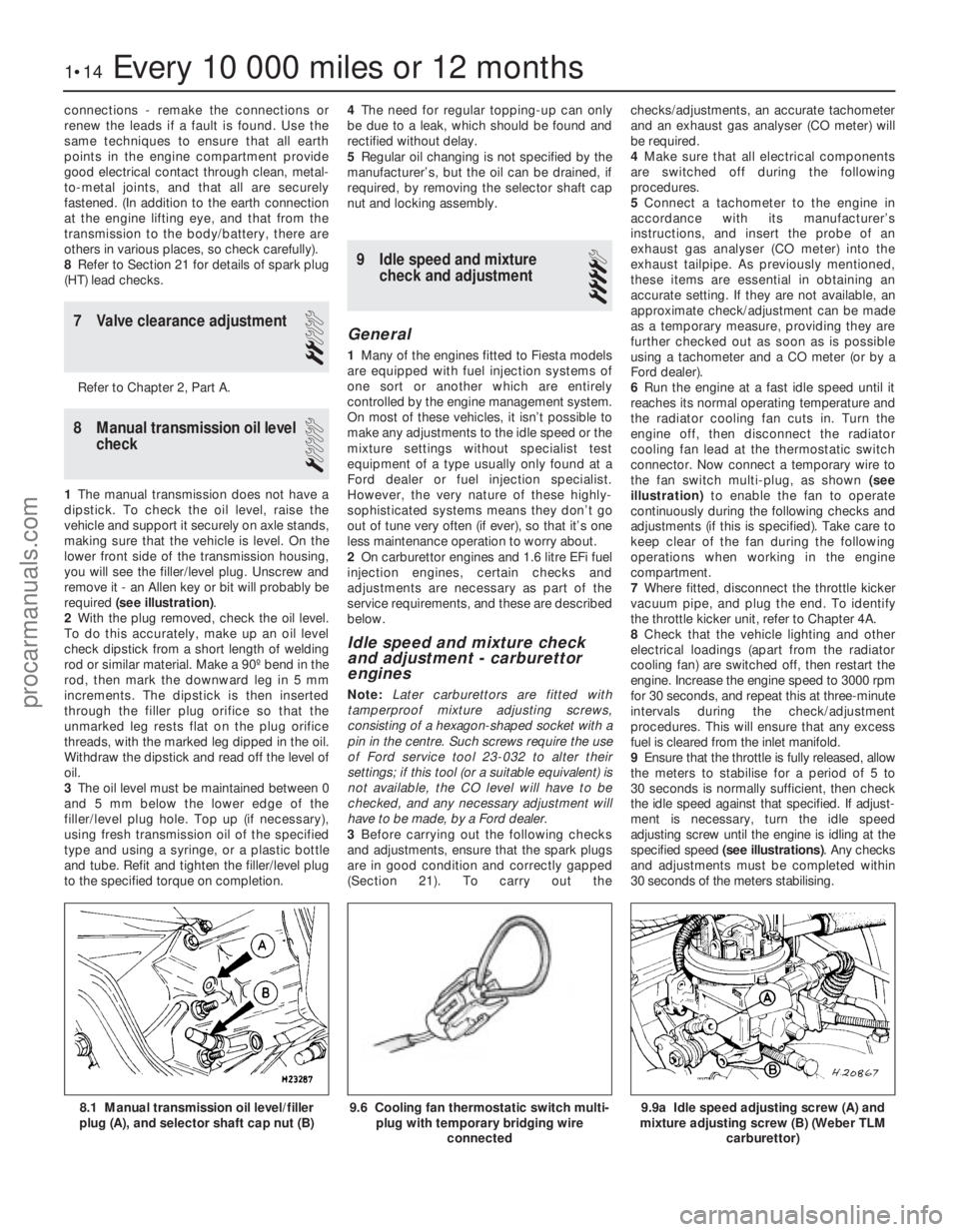
1The manual transmission does not have a
dipstick. To check the oil level, raise the
vehicle and support it securely on axle stands,
making sure that the vehicle is level. On the
lower front side of the transmission housing,
you will see the filler/level plug. Unscrew and
remove it - an Allen key or bit will probably be
required (see illustration) .
2 With the plug removed, check the oil level.
To do this accurately, make up an oil level
check dipstick from a short length of welding
rod or similar material. Make a 90º bend in the
rod, then mark the downward leg in 5 mm
increments. The dipstick is then inserted
through the filler plug orifice so that the
unmarked leg rests flat on the plug orifice
threads, with the marked leg dipped in the oil.
Withdraw the dipstick and read off the level of
oil.
3 The oil level must be maintained between 0
and 5 mm below the lower edge of the
filler/level plug hole. Top up (if necessary),
using fresh transmission oil of the specified
type and using a syringe, or a plastic bottle
and tube. Refit and tighten the filler/level plug
to the specified torque on completion. 4
The need for regular topping-up can only
be due to a leak, which should be found and
rectified without delay.
5 Regular oil changing is not specified by the
manufacturer’s, but the oil can be drained, if
required, by removing the selector shaft cap
nut and locking assembly.
9 Idle speed and mixture check and adjustment
4
General
1Many of the engines fitted to Fiesta models
are equipped with fuel injection systems of
one sort or another which are entirely
controlled by the engine management system.
On most of these vehicles, it isn’t possible to
make any adjustments to the idle speed or the
mixture settings without specialist test
equipment of a type usually only found at a
Ford dealer or fuel injection specialist.
However, the very nature of these highly-
sophisticated systems means they don’t go
out of tune very often (if ever), so that it’s one
less maintenance operation to worry about.
2 On carburettor engines and 1.6 litre EFi fuel
injection engines, certain checks and
adjustments are necessary as part of the
service requirements, and these are described
below.
Idle speed and mixture check
and adjustment - carburettor
engines
Note: Later carburettors are fitted with
tamperproof mixture adjusting screws,
consisting of a hexagon-shaped socket with a
pin in the centre. Such screws require the use
of Ford service tool 23-032 to alter their
settings; if this tool (or a suitable equivalent) is
not available, the CO level will have to be
checked, and any necessary adjustment will
have to be made, by a Ford dealer.
3 Before carrying out the following checks
and adjustments, ensure that the spark plugs
are in good condition and correctly gapped
(Section 21). To carry out the checks/adjustments, an accurate tachometer
and an exhaust gas analyser (CO meter) will
be required.
4
Make sure that all electrical components
are switched off during the following
procedures.
5 Connect a tachometer to the engine in
accordance with its manufacturer’s
instructions, and insert the probe of an
exhaust gas analyser (CO meter) into the
exhaust tailpipe. As previously mentioned,
these items are essential in obtaining an
accurate setting. If they are not available, an
approximate check/adjustment can be made
as a temporary measure, providing they are
further checked out as soon as is possible
using a tachometer and a CO meter (or by a
Ford dealer).
6 Run the engine at a fast idle speed until it
reaches its normal operating temperature and
the radiator cooling fan cuts in. Turn the
engine off, then disconnect the radiator
cooling fan lead at the thermostatic switch
connector. Now connect a temporary wire to
the fan switch multi-plug, as shown (see
illustration) to enable the fan to operate
continuously during the following checks and
adjustments (if this is specified). Take care to
keep clear of the fan during the following
operations when working in the engine
compartment.
7 Where fitted, disconnect the throttle kicker
vacuum pipe, and plug the end. To identify
the throttle kicker unit, refer to Chapter 4A.
8 Check that the vehicle lighting and other
electrical loadings (apart from the radiator
cooling fan) are switched off, then restart the
engine. Increase the engine speed to 3000 rpm
for 30 seconds, and repeat this at three-minute
intervals during the check/adjustment
procedures. This will ensure that any excess
fuel is cleared from the inlet manifold.
9 Ensure that the throttle is fully released, allow
the meters to stabilise for a period of 5 to
30 seconds is normally sufficient, then check
the idle speed against that specified. If adjust-
ment is necessary, turn the idle speed
adjusting screw until the engine is idling at the
specified speed (see illustrations) . Any checks
and adjustments must be completed within
30 seconds of the meters stabilising.
1•14Every 10 000 miles or 12 months
9.9a Idle speed adjusting screw (A) and
mixture adjusting screw (B) (Weber TLM
carburettor)9.6 Cooling fan thermostatic switch multi-plug with temporary bridging wire
connected8.1 Manual transmission oil level/filler
plug (A), and selector shaft cap nut (B)
1595Ford Fiesta Remakeprocarmanuals.com
http://vnx.su
Page 16 of 296
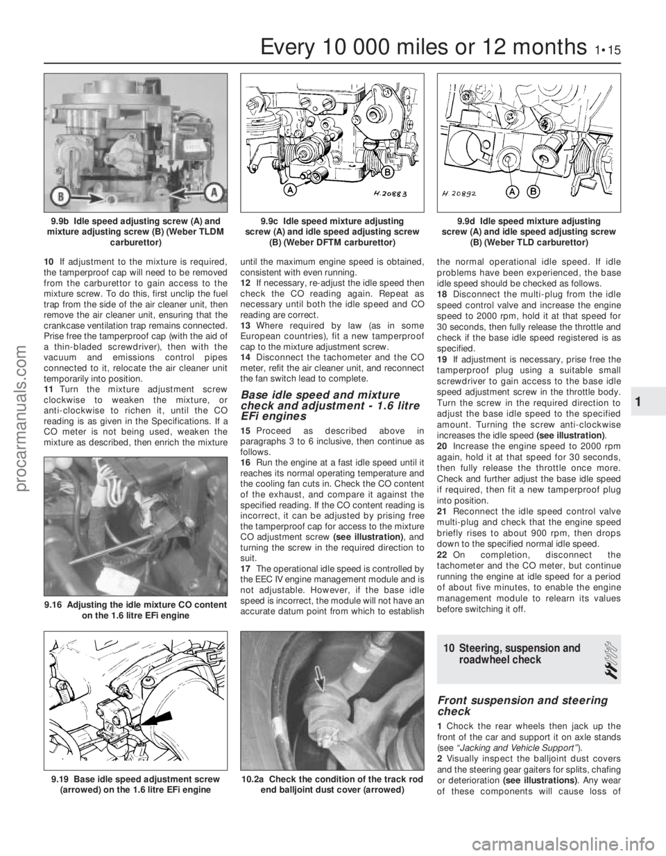
10If adjustment to the mixture is required,
the tamperproof cap will need to be removed
from the carburettor to gain access to the
mixture screw. To do this, first unclip the fuel
trap from the side of the air cleaner unit, then
remove the air cleaner unit, ensuring that the
crankcase ventilation trap remains connected.
Prise free the tamperproof cap (with the aid of
a thin-bladed screwdriver), then with the
vacuum and emissions control pipes
connected to it, relocate the air cleaner unit
temporarily into position.
11 Turn the mixture adjustment screw
clockwise to weaken the mixture, or
anti-clockwise to richen it, until the CO
reading is as given in the Specifications. If a
CO meter is not being used, weaken the
mixture as described, then enrich the mixture until the maximum engine speed is obtained,
consistent with even running.
12
If necessary, re-adjust the idle speed then
check the CO reading again. Repeat as
necessary until both the idle speed and CO
reading are correct.
13 Where required by law (as in some
European countries), fit a new tamperproof
cap to the mixture adjustment screw.
14 Disconnect the tachometer and the CO
meter, refit the air cleaner unit, and reconnect
the fan switch lead to complete.
Base idle speed and mixture
check and adjustment - 1.6 litre
EFi engines
15 Proceed as described above in
paragraphs 3 to 6 inclusive, then continue as
follows.
16 Run the engine at a fast idle speed until it
reaches its normal operating temperature and
the cooling fan cuts in. Check the CO content
of the exhaust, and compare it against the
specified reading. If the CO content reading is
incorrect, it can be adjusted by prising free
the tamperproof cap for access to the mixture
CO adjustment screw (see illustration), and
turning the screw in the required direction to
suit.
17 The operational idle speed is controlled by
the EEC IV engine management module and is
not adjustable. However, if the base idle
speed is incorrect, the module will not have an
accurate datum point from which to establish the normal operational idle speed. If idle
problems have been experienced, the base
idle speed should be checked as follows.
18
Disconnect the multi-plug from the idle
speed control valve and increase the engine
speed to 2000 rpm, hold it at that speed for
30 seconds, then fully release the throttle and
check if the base idle speed registered is as
specified.
19 If adjustment is necessary, prise free the
tamperproof plug using a suitable small
screwdriver to gain access to the base idle
speed adjustment screw in the throttle body.
Turn the screw in the required direction to
adjust the base idle speed to the specified
amount. Turning the screw anti-clockwise
increases the idle speed (see illustration).
20 Increase the engine speed to 2000 rpm
again, hold it at that speed for 30 seconds,
then fully release the throttle once more.
Check and further adjust the base idle speed
if required, then fit a new tamperproof plug
into position.
21 Reconnect the idle speed control valve
multi-plug and check that the engine speed
briefly rises to about 900 rpm, then drops
down to the specified normal idle speed.
22 On completion, disconnect the
tachometer and the CO meter, but continue
running the engine at idle speed for a period
of about five minutes, to enable the engine
management module to relearn its values
before switching it off.
10 Steering, suspension and roadwheel check
2
Front suspension and steering
check
1Chock the rear wheels then jack up the
front of the car and support it on axle stands
(see “Jacking and Vehicle Support” ).
2 Visually inspect the balljoint dust covers
and the steering gear gaiters for splits, chafing
or deterioration (see illustrations) . Any wear
of these components will cause loss of
Every 10 000 miles or 12 months1•15
9.9d Idle speed mixture adjusting
screw (A) and idle speed adjusting screw (B) (Weber TLD carburettor)9.9c Idle speed mixture adjusting
screw (A) and idle speed adjusting screw (B) (Weber DFTM carburettor)9.9b Idle speed adjusting screw (A) and
mixture adjusting screw (B) (Weber TLDM carburettor)
10.2a Check the condition of the track rodend balljoint dust cover (arrowed)9.19 Base idle speed adjustment screw(arrowed) on the 1.6 litre EFi engine
9.16 Adjusting the idle mixture CO content on the 1.6 litre EFi engine
1
1595Ford Fiesta Remakeprocarmanuals.com
http://vnx.su
Page 23 of 296
the corrosion which would otherwise occur
as the corrosion inhibitors become progress-
ively less effective. Always use an ethylene
glycol-based antifreeze which is suitable for
use in mixed-metal cooling systems.
20If the antifreeze used is to Ford’s
specification, the levels of protection it affords
are indicated in the Specifications Section of
this Chapter. To give the recommended
standard mixture ratio for this antifreeze, 40%
(by volume) of antifreeze must be mixed with
60% of clean, soft water; if you are using any
other type of antifreeze, follow its
manufacturer’s instructions to achieve the
correct ratio. It is best to make up slightly
more than the system’s specified capacity, so
that a supply is available for subsequent
topping-up.
21 Before adding antifreeze, the cooling
system should be completely drained,
preferably flushed, and all hoses checked for
condition and security. As noted earlier, fresh
antifreeze will rapidly find any weaknesses in
the system.
22 After filling with antifreeze, a label should
be attached to the expansion tank, stating the
type and concentration of antifreeze used,
and the date installed. Any subsequent
topping-up should be made with the same
type and concentration of antifreeze. If
topping-up using antifreeze to Ford’s
specification, note that a 50/50 mixture is
permissible, purely for convenience.
23 Do not use engine antifreeze in the
windscreen/tailgate washer system, as it will
damage the vehicle’s paintwork. A
screenwash additive should be added to the
washer system in its maker’s recommended
quantities.
Antifreeze - notes on renewal
24 Ford state that, where antifreeze to Ford
specification ESD-M97B-49-A is used, it will
last the lifetime of the vehicle. This is subject
to it being used in the recommended
concentration, unmixed with any other type of
antifreeze or additive, and topped-up when
necessary using only that antifreeze mixed 50/50 with clean water. If any other type of
antifreeze is added, the lifetime guarantee no
longer applies; to restore the lifetime
protection, the system must be drained and
thoroughly reverse-flushed before fresh
coolant mixture is poured in.
25
If the vehicle’s history (and therefore the
quality of the antifreeze in it) is unknown,
owners who wish to follow Ford’s
recommendations are advised to drain and
thoroughly reverse-flush the system before
refilling with fresh coolant mixture. If the
appropriate quality of antifreeze is used, the
coolant can then be left for the life of the
vehicle.
26 If any antifreeze other than Ford’s is to be
used, the coolant must be renewed at regular
intervals to provide an equivalent degree of
protection; the conventional recommendation
is to renew the coolant every two or three
years.
27 The above assumes the use of a mixture
(in exactly the specified concentration) of
clean, soft water and of antifreeze to Ford’s
specification or equivalent. It is also assumed
that the cooling system is maintained in a
scrupulously-clean condition, by ensuring that
only clean coolant is added on topping-up,
and by thorough reverse-flushing whenever
the coolant is drained.
General cooling system checks
28 The engine should be cold for the cooling
system checks, so perform the following
procedure before driving the vehicle, or
after it has been shut off for at least three
hours.
29 Remove the expansion tank filler cap, and
clean it thoroughly inside and out with a rag.
Also clean the filler neck on the expansion
tank. The presence of rust or corrosion in the
filler neck indicates that the coolant should be
changed. The coolant inside the expansion
tank should be relatively clean and
transparent. If it is rust-coloured, drain and
flush the system, and refill with a fresh coolant
mixture.
30 Carefully check the radiator hoses and heater hoses along their entire length; renew
any hose which is cracked, swollen or
deteriorated (see Section 5).
31
Inspect all other cooling system
components (joint faces, etc.) for leaks. A leak
in the cooling system will usually show up as
white- or rust-coloured deposits on the area
adjoining the leak. Where any problems of this
nature are found on system components,
renew the component or gasket with
reference to Chapter 3.
32 Clean the front of the radiator with a soft
brush to remove all insects, leaves, etc,
embedded in the radiator fins. Be careful not
to damage the radiator fins, or cut your fingers
on them.
24 Air cleaner element renewal
1
1 The air cleaner filter element is located in
the air cleaner assembly mounted either on
top of the carburettor or CFi unit, or on the
left-hand or right-hand side of the engine
compartment at the front. Remove the air
cleaner lid as follows according to type.
Carburettor and CFi fuel
injection models
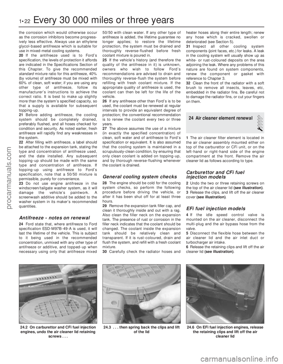
2 Undo the two or three retaining screws on
the top of the air cleaner lid (see illustration).
3 Release the clips, and lift off the air cleaner
cover (see illustration) .
EFi fuel injection models
4If the idle speed control valve is
mounted on the air cleaner, disconnect the
multi-plug and the air bypass hose from the
valve.
5 Disconnect the flexible hose between the
air cleaner lid and the air inlet duct or
turbocharger air intake.
6 Release the retaining clips and lift off the air
cleaner lid (see illustration) .
1•22Every 30 000 miles or three years
24.6 On EFi fuel injection engines, release
the retaining clips and lift off the air
cleaner lid24.3 . . . then spring back the clips and lift of the lid24.2 On carburettor and CFi fuel injectionengines, undo the air cleaner lid retaining
screws . . .
1595Ford Fiesta Remakeprocarmanuals.com
http://vnx.su
Page 26 of 296
the specified type of fluid. It is essential that
no dirt is introduced into the transmission
during this operation.
7Depending on the extent to which the fluid
was allowed to drain, it is possible that the
amount of fluid required when filling the
transmission may be more than the specified
amount (see “Lubricants, fluids and tyre
pressures” ). However, due to fluid remaining in
the system, it is more likely that less than the
specified amount will be required. Add about
half the specified amount, then run the engine
up to its normal operating temperature and
check the level on the dipstick. When the level
approaches the maximum mark, proceed as
detailed in Section 20 to check the level and
complete the final topping-up as described.
27 Handbrake adjustment
3
1 Chock the front wheels then jack up the
rear of the car and support it on axle stands
(see “Jacking and Vehicle Support” ). Fully
release the handbrake.
2 Check that the handbrake cables are
correctly routed and secured by the retaining
clips at the appropriate points under the vehicle.
3 The handbrake is checked for adjustment
by measuring the amount of movement
possible in the handbrake adjuster plungers.
These are located on the inside face of each
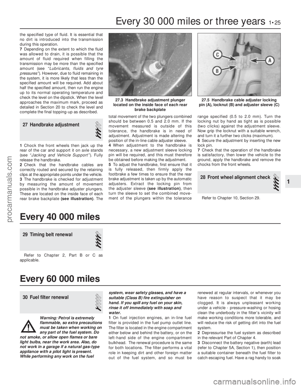
rear brake backplate (see illustration) . Thetotal movement of the two plungers combined
should be between 0.5 and 2.0 mm. If the
movement measured is outside of this
tolerance, the handbrake is in need of
adjustment. Adjustment is made altering the
position of the in-line cable adjuster sleeve.
4
When adjustment to the handbrake is
necessary, a new adjustment sleeve locking
pin will be required, and this must therefore
be obtained before making the adjustment.
5 To adjust the handbrake, first ensure that it
is fully released, then firmly apply the
footbrake a few times to ensure that the rear
brake adjustment is taken up by the automatic
adjusters. Extract the locking pin from
the adjuster sleeve (see illustration), then
turn the sleeve to set the combined move-
ment of the plungers within the tolerance range specified (0.5 to 2.0 mm). Turn the
locking nut by hand as tight as is possible
(two clicks) against the adjustment sleeve.
Now grip the locknut with a suitable wrench,
and turn it a further two clicks (maximum).
6
Secure the adjustment by inserting the new
lock pin.
7 Check that the operation of the handbrake
is satisfactory, then lower the vehicle to the
ground, apply the handbrake and remove the
chocks from the front wheels.
28 Front wheel alignment check
4
Refer to Chapter 10, Section 29.
Every 30 000 miles or three years1•25
27.5 Handbrake cable adjuster locking
pin (A), locknut (B) and adjuster sleeve (C)27.3 Handbrake adjustment plunger
located on the inside face of each rear brake backplate
1
1595Ford Fiesta Remake
Every 40 000 miles
29 Timing belt renewal
4
Refer to Chapter 2, Part B or C as
applicable.
Every 60 000 miles
30 Fuel filter renewal
1
Warning: Petrol is extremely
flammable, so extra precautions
must be taken when working on
any part of the fuel system. Do
not smoke, or allow open flames or bare
light bulbs, near the work area. Also, do
not work in a garage if a natural gas-type appliance with a pilot light is present.
While performing any work on the fuel system, wear safety glasses, and have a
suitable (Class B) fire extinguisher on
hand. If you spill any fuel on your skin,
rinse it off immediately with soap and
water.
1
On fuel injection engines, an in-line fuel
filter is provided in the fuel pump outlet line.
The filter is located in the engine compartment
either below and behind the battery, or on the
left-hand side of the engine compartment
bulkhead. The renewal procedure is the same
for both locations. The filter performs a vital
role in keeping dirt and other foreign matter
out of the fuel system, and so must be renewed at regular intervals, or whenever you
have reason to suspect that it may be
clogged. It is always unpleasant working
under a vehicle - pressure-washing or hosing
clean the underbody in the filter’s vicinity will
make working conditions more tolerable, and
will reduce the risk of getting dirt into the fuel
system.
2
Depressurise the fuel system as described
in the relevant Part of Chapter 4.
3 Disconnect the battery negative (earth) lead
(refer to Chapter 5A, Section 1), then position
a suitable container beneath the fuel filter to
catch escaping fuel. Have a rag handy to soak
procarmanuals.com
http://vnx.su
Page 79 of 296
25Unscrew the retaining bolt, and detach
the shift rod stabiliser from the transmission.
As it is detached, note the washer located
between the stabiliser and the transmission.
Tie the stabiliser and the shift rod up out of
the way.
Automatic transmission models
26 Unclip and detach the wiring connector
from the starter inhibitor switch (on the
transmission housing).
27 Referring to the relevant Part of Chapter 4
for details, unhook the accelerator (cam plate)
cable from the carburettor or fuel injection unit
(as applicable) at the transmission end of
the cable. Undo the retaining bolt and
detach the cable sheath bracket from the
transmission. Detach the cam plate cable
from the link.
28 Undo the two nuts from the selector cable
bracket which connects it to the lever on the
selector shaft. Disconnect the yoke from the
lever on the selector shaft and the cable from
the lever.
29 Unscrew the union nuts, and disconnect
the oil cooler feed and return pipes from the
transmission. Allow for a certain amount of
spillage, and plug the connections to prevent
the ingress of dirt.
All models
30 Unscrew the retaining nut and withdraw
the Torx-type clamp bolt securing the lower
suspension arm to the spindle carrier on each
side.
31 Refer to Chapter 10 for details, and
detach the right-hand and left-hand track rod
end balljoints from the spindle carriers.
32 On vehicles fitted with the anti-lock
braking system, refer to Chapter 9 and release
the right-hand modulator from its mounting
bracket without disconnecting the rigid brake
pipes or return hose. Tie the modulator
securely to the bulkhead. Additionally, undo
the three bolts securing the modulator
bracket.
33 Insert a suitable lever between the right-
hand driveshaft inner joint and the
transmission housing, and prise free the
driveshaft from the transmission; be prepared
for oil spillage from the transmission case
through the vacated driveshaft aperture. As it
is being prised free, simultaneously pull the
roadwheel outwards on that side, to enable
the driveshaft inboard end to separate
from the transmission. Once it is free,
suspend and support the driveshaft from the
steering gear, to prevent unnecessary strain
being placed on the driveshaft joints.
34 Insert a suitable plastic plug (or if
available, an old driveshaft joint), into the
transmission driveshaft aperture, to
immobilise the gears of the differential unit.
35 Proceed as described above in
paragraphs 33 and 34, and disconnect the
left-hand driveshaft from the transmission.
36 Connect a suitable lift hoist and sling to
the engine, connecting to the lifting eyes. When securely connected, take the weight of
the engine/transmission unit so that the
tension is relieved from the mountings.
37
Undo the retaining bolts and nuts and
detach the right-hand engine mounting from
the vehicle body.
38 Undo the four bolts securing the
transmission bearer to the underside of the
vehicle body. The transmission bearer is
removed with the engine/transmission
assembly.
39 Unscrew the three retaining bolts, and
remove the auxiliary drivebelt cover from
under the crankshaft pulley.
40 The engine/transmission unit should now
be ready for removal from the vehicle. Check
that all of the associated connections and
fittings are disconnected from the engine and
transmission, and positioned out of the way.
41 Enlist the aid of an assistant to help
steady and guide the power unit down
through the engine compartment as it is
removed. If available, position a suitable
engine trolley or crawler board under the
engine/transmission so that when lowered,
the power unit can be withdrawn from the
front end of the vehicle, and then moved to
the area where it is to be cleaned and
dismantled. On automatic transmission
models, particular care must be taken not to
damage the transmission fluid pan (sump)
during the removal and subsequent refitting
processes.
42 Carefully lower the engine and
transmission unit, ensuring that no fittings
become snagged. Detach the hoist and
remove the power unit from under the vehicle.
43 Referring to the relevant Part of Chapter 7,
separate the transmission from the engine.
44 While the engine/transmission is removed,
check the mountings; renew them if they are
worn or damaged. Similarly, check the
condition of all coolant and vacuum hoses
and pipes (see Chapter 1). Components that
are normally hidden can now be checked
properly, and should be renewed if there is
any doubt at all about their condition. Where
the vehicle is fitted with manual transmission,
take the opportunity to inspect the clutch
components (see Chapter 6). It is regarded by
many as good working practice to renew the
clutch assembly as a matter of course,
whenever major engine overhaul work is
carried out. Check also the condition of all
components (such as the transmission oil
seals) disturbed on removal, and renew any
that are damaged or worn.
Refitting
45 Refitting is a reversal of removal, however
note the following additional points:
a) Refer to the applicable Chapters and Sections as for removal.
b) Fit new spring clips to the grooves in the
inboard end of the right- and left-hand
driveshaft joints. Lubricate the splines
with transmission oil prior to fitting. c) Renew the exhaust flange gasket when
reconnecting the exhaust. Ensure that all
wires are routed clear of the exhaust
system and, on catalytic converter
models, ensure that the heat shields are
securely and correctly fitted.
d) Ensure that all earth lead connections are
clean and securely made.
e) Tighten all nuts and bolts to the specified torque.
f) Fit a new oil filter, and refill the engine and transmission with oil, with reference to
Chapter 1.
g) Refill the cooling system with reference to Chapter 1.
h) Refit the alternator and starter motor with reference to Chapter 5A.
i) Where applicable, refit the power steering pump with reference to Chapter 10.
46 When engine and transmission refitting is
complete, refer to the procedures described
in Section 19 before restarting the engine.
5 Engine/transmission -
removal and refitting
(Zetec engines)
3
Warning: Petrol is extremely
flammable, so take extra
precautions when disconnecting
any part of the fuel system.
Don’t smoke, or allow naked flames or
bare light bulbs, in or near the work area,
and don’t work in a garage where a
natural-gas appliance (such as a clothes
dryer or water heater) is installed. If you
spill petrol on your skin, rinse it off
immediately. Have a fire extinguisher rated
for petrol fires handy, and know how to
use it.
Note: Read through the entire Section, as well
as reading the advice in Section 2, before
beginning this procedure. The engine and
transmission are removed as a unit, lowered to
the ground and removed from underneath,
then separated outside the vehicle.
Removal
1 Park the vehicle on firm, level ground, apply
the handbrake firmly, and slacken the nuts
securing both front roadwheels.
2 Depressurise the fuel system as described
in Chapter 4D.
3 Disconnect the battery negative (earth) lead
(refer to Chapter 5A, Section 1).
4 Place protective covers on the wings, then
remove the bonnet (see Chapter 11).
5 Drain the cooling system and the engine oil
(see Chapter 1).
6 Remove the air inlet components and the
complete air cleaner assembly as described in
Chapter 4D.
7 Equalise the pressure in the fuel tank by
removing the filler cap, then release the fuel
feed and return quick-release couplings, and
pull the hoses off the fuel pipes. Plug or cap
all open fittings.
2D•10 Engine removal and overhaul procedures
1595Ford Fiesta Remakeprocarmanuals.com
http://vnx.su
Page 80 of 296
8Disconnect the accelerator cable from the
throttle linkage as described in Chapter 4D.
Secure the cable clear of the
engine/transmission.
9 Releasing its wire clip, unplug the wiring
connector from the power steering pressure
switch (where fitted), then disconnect the
earth cable from the engine lifting eye. Refit
the bolt after disconnecting the cable.
10 Marking or labelling all components as
they are disconnected, disconnect the
vacuum hoses as follows:
a) From the rear of the inlet manifold.
b) The braking system vacuum servo unit
hose - from the inlet manifold (see
Chapter 9 for details).
c) While you are there, trace the vacuum line
from the pulse-air filter housing, and
disconnect it from the pulse-air solenoid
valve.
d) Secure all these hoses so that they won’t
get damaged as the engine/transmission
is removed.
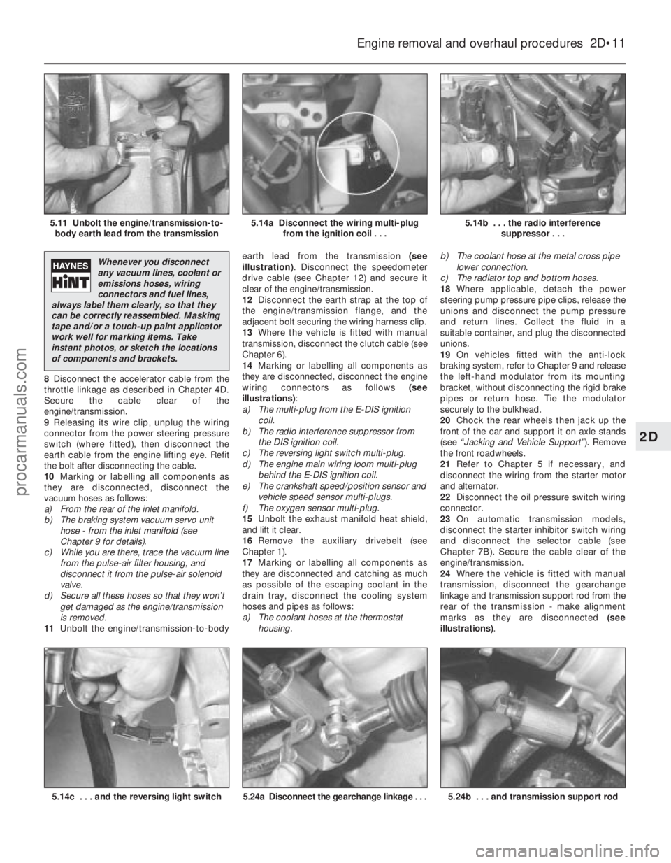
11 Unbolt the engine/transmission-to-body earth lead from the transmission
(see
illustration) . Disconnect the speedometer
drive cable (see Chapter 12) and secure it
clear of the engine/transmission.
12 Disconnect the earth strap at the top of
the engine/transmission flange, and the
adjacent bolt securing the wiring harness clip.
13 Where the vehicle is fitted with manual
transmission, disconnect the clutch cable (see
Chapter 6).
14 Marking or labelling all components as
they are disconnected, disconnect the engine
wiring connectors as follows (see
illustrations) :
a) The multi-plug from the E-DIS ignition
coil.
b) The radio interference suppressor from
the DIS ignition coil.
c) The reversing light switch multi-plug.
d) The engine main wiring loom multi-plug
behind the E-DIS ignition coil.
e) The crankshaft speed/position sensor and vehicle speed sensor multi-plugs.
f) The oxygen sensor multi-plug.
15 Unbolt the exhaust manifold heat shield,
and lift it clear.
16 Remove the auxiliary drivebelt (see
Chapter 1).
17 Marking or labelling all components as
they are disconnected and catching as much
as possible of the escaping coolant in the
drain tray, disconnect the cooling system
hoses and pipes as follows:
a) The coolant hoses at the thermostat housing. b)
The coolant hose at the metal cross pipe
lower connection.
c) The radiator top and bottom hoses.
18 Where applicable, detach the power
steering pump pressure pipe clips, release the
unions and disconnect the pump pressure
and return lines. Collect the fluid in a
suitable container, and plug the disconnected
unions.
19 On vehicles fitted with the anti-lock
braking system, refer to Chapter 9 and release
the left-hand modulator from its mounting
bracket, without disconnecting the rigid brake
pipes or return hose. Tie the modulator
securely to the bulkhead.
20 Chock the rear wheels then jack up the
front of the car and support it on axle stands
(see “Jacking and Vehicle Support” ). Remove
the front roadwheels.
21 Refer to Chapter 5 if necessary, and
disconnect the wiring from the starter motor
and alternator.
22 Disconnect the oil pressure switch wiring
connector.
23 On automatic transmission models,
disconnect the starter inhibitor switch wiring
and disconnect the selector cable (see
Chapter 7B). Secure the cable clear of the
engine/transmission.
24 Where the vehicle is fitted with manual
transmission, disconnect the gearchange
linkage and transmission support rod from the
rear of the transmission - make alignment
marks as they are disconnected (see
illustrations) .
Engine removal and overhaul procedures 2D•11
5.14b . . . the radio interference
suppressor . . .5.14a Disconnect the wiring multi-plugfrom the ignition coil . . .5.11 Unbolt the engine/transmission-to-body earth lead from the transmission
5.24b . . . and transmission support rod5.24a Disconnect the gearchange linkage . . .5.14c . . . and the reversing light switch
2D
1595Ford Fiesta Remake
Whenever you disconnect
any vacuum lines, coolant or
emissions hoses, wiring
connectors and fuel lines,
always label them clearly, so that they
can be correctly reassembled. Masking
tape and/or a touch-up paint applicator
work well for marking items. Take
instant photos, or sketch the locations
of components and brackets.
procarmanuals.com
http://vnx.su
Page 108 of 296
1 General information andprecautions
General information
The fuel system on all models with
carburettor induction comprises a rear-
mounted fuel tank, a mechanical diaphragm
fuel pump, a carburettor and an air cleaner. The fuel tank is mounted at the rear, under
the floorpan behind the rear seats. The tank
has a “ventilation-to-atmosphere system”
through a combined roll-over/anti-trickle fill
valve assembly, located in the left-hand rear
wheel arch. A filler neck sensing pipe, integral
with the fuel tank filler pipe, will shut off the
petrol pump filler gun when the predetermined
maximum level of fuel is reached in the tank,
so preventing spillage and wastage. A
conventional fuel level sender unit is mounted
in the top face of the fuel tank. One of two fuel pump types will be fitted,
depending on the engine type. On HCS
engines, the fuel pump is operated by a
pivoting rocker arm; one end rests on an
eccentric lobe on the engine camshaft, and
the other end is attached to the fuel pump
diaphragm. The pump fitted to the CVH
engine is operated by a separate pushrod,
one end rests on an eccentric lobe on the
engine camshaft, and the other rests on the
pump actuating rod which operates the
diaphragm. Both types of mechanical pump
incorporate a nylon mesh filter, and are of
sealed type (they cannot be serviced or
overhauled). Four different types of Weber carburettor
are featured in the range, further details being
given in later Sections of this Chapter. The air cleaner incorporates a “waxstat”
controlled air inlet, supplying either hot air
from a shroud mounted around the exhaust
manifold, or cool air from a duct in the front of
the vehicle.
Precautions
Warning: Petrol is extremely
flammable - great care must be
taken when working on any part of the fuel system. Do not smoke or allow
any naked flames or uncovered light bulbs
near the work area. Note that gas powered
domestic appliances with pilot flames,
such as heaters, boilers and tumble
dryers, also present a fire hazard - bear
this in mind if you are working in an area
where such appliances are present.
Always keep a suitable fire extinguisher
close to the work area and familiarise
yourself with its operation before starting
work. Wear eye protection when working
on fuel systems and wash off any fuel spilt
on bare skin immediately with soap and
water. Note that fuel vapour is just as
dangerous as liquid fuel; a vessel that has
just been emptied of liquid fuel will still
contain vapour and can be potentially
explosive. Petrol is a highly dangerous and
volatile liquid, and the precautions
necessary when handling it cannot be
overstressed.
Many of the operations described in this
Chapter involve the disconnection of fuel
lines, which may cause an amount of fuel
spillage. Before commencing work, refer
to the above Warning and the information
in “Safety first” at the beginning of this
manual.
When working with fuel system
components, pay particular attention to
cleanliness - dirt entering the fuel system
may cause blockages which will lead to
poor running.
Certain adjustment points in the fuel system
are protected by tamperproof caps, plugs or
seals. In some territories, it is an offence to
drive a vehicle with broken or missing
tamperproof seals. Before disturbing a
tamperproof seal, first check that no local or
national laws will be broken by doing so, and
fit a new tamperproof seal after adjustment is
complete, where required by law. Do not
break tamperproof seals on any vehicle whilst
it is still under warranty. Carburettors are delicate instruments, and
care must be taken not to disturb any
components unnecessarily. Before attempting
work on a carburettor, ensure that the relevant
spares are available; it should be noted that a complete strip down of a carburettor is
unlikely to cure a fault which is not
immediately obvious, without introducing new
problems. If persistent problems occur, it is
recommended that the services of a Ford
dealer or a carburettor specialist are sought.
Most dealers will be able to provide
carburettor rejetting and servicing facilities.
Where necessary, it may be possible to
purchase a reconditioned carburettor.
2 Air cleaner
-
removal and refitting
1
Note: Air cleaner element renewal and air
cleaner temperature control system checks
are described in Chapter 1.
Removal
1 Disconnect the battery negative (earth) lead
(refer to Chapter 5A, Section 1).
2 On CVH engine models, pull free and
release the accelerator cable from the locating
clip on the side of the air cleaner.
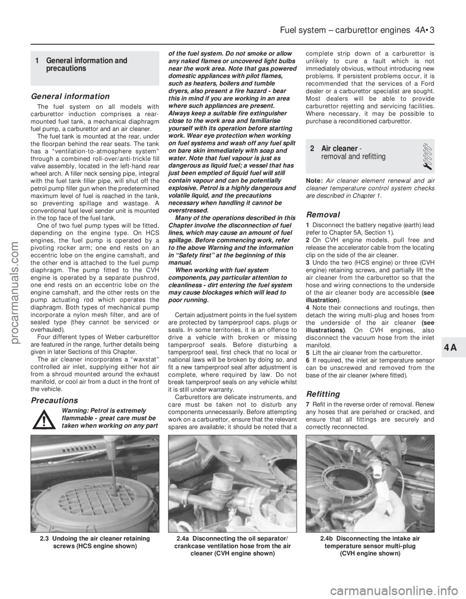
3 Undo the two (HCS engine) or three (CVH
engine) retaining screws, and partially lift the
air cleaner from the carburettor so that the
hose and wiring connections to the underside
of the air cleaner body are accessible (see
illustration) .
4 Note their connections and routings, then
detach the wiring multi-plug and hoses from
the underside of the air cleaner (see
illustrations) . On CVH engines, also
disconnect the vacuum hose from the inlet
manifold.
5 Lift the air cleaner from the carburettor.
6 If required, the inlet air temperature sensor
can be unscrewed and removed from the
base of the air cleaner (where fitted).
Refitting
7 Refit in the reverse order of removal. Renew
any hoses that are perished or cracked, and
ensure that all fittings are securely and
correctly reconnected.
Fuel system – carburettor engines 4A•3
2.4b Disconnecting the intake air temperature sensor multi-plug
(CVH engine shown)2.4a Disconnecting the oil separator/
crankcase ventilation hose from the air
cleaner (CVH engine shown)2.3 Undoing the air cleaner retainingscrews (HCS engine shown)
4A
1595Ford Fiesta Remakeprocarmanuals.com
http://vnx.su
Page 110 of 296
position at the carburettor, then secure the
outer cable with its retaining clip.
Adjustment
12To check that the choke cable is correctly
adjusted, the control knob must be pulled out
to the full-on position and the choke lever
must be in contact with its stop. Adjust as
required if necessary.
13 Press the choke knob fully in (to the off
position), then check that the choke linkage at
the carburettor has fully returned to its off
position and the choke valve plate in the
carburettor is at a right angle (90º) to the
venturi.
14 Refit the air cleaner.
15 Reconnect the battery, turn the ignition
on, operate the choke and check that the
choke warning light operates correctly.
7 Fuel pump -
testing, removal and refitting
2
Note: Refer to the warning note in Section 1
before proceeding.
Testing
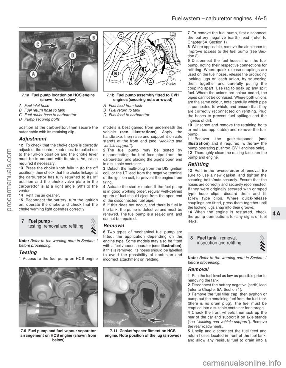
1 Access to the fuel pump on HCS engine models is best gained from underneath the
vehicle
(see illustrations) . Apply the
handbrake, then raise and support it on axle
stands at the front end (see “Jacking and
vehicle support” ).
2 The fuel pump may be tested by
disconnecting the fuel feed pipe from the
carburettor, and placing the pipe’s open end
in a suitable container.
3 Detach the multi-plug from the DIS ignition
coil, or the LT lead from the negative terminal
of the ignition coil, to prevent the engine from
firing.
4 Actuate the starter motor. If the fuel pump
is in good working order, regular well-defined
spurts of fuel should eject from the open end
of the disconnected fuel pipe.
5 If this does not occur, and there is fuel in
the tank, the pump is defective and must be
renewed. The fuel pump is a sealed unit, and
cannot be repaired.
Removal
6 Two types of mechanical fuel pump are
fitted, the application depending on the
engine type. Some models may also be fitted
with a fuel vapour separator (see illustration) ;
if this is removed, its hoses should be labelled
to avoid the possibility of confusion and
incorrect attachment on refitting. 7
To remove the fuel pump, first disconnect
the battery negative (earth) lead (refer to
Chapter 5A, Section 1).
8 Where applicable, remove the air cleaner to
improve access to the fuel pump (see Sec-
tion 2).
9 Disconnect the fuel hoses from the fuel
pump, noting their respective connections for
refitting. Where quick-release couplings are
used on the fuel hoses, release the protruding
locking lugs on each union, by squeezing
them together and carefully pulling the
coupling apart. Use rag to soak up any spilt
fuel. Where the unions are colour-coded, the
pipes cannot be confused. Where both unions
are the same colour, note carefully which pipe
is connected to which, and ensure that they
are correctly reconnected on refitting. Plug
the hoses to prevent fuel spillage and the
ingress of dirt.
10 Unscrew and remove the retaining bolts
or nuts (as applicable) and remove the fuel
pump.
11 Recover the gasket/spacer (see
illustration) and if required, withdraw the
pump operating pushrod (CVH engines only).
12 Thoroughly clean the mating faces on the
pump and engine.
Refitting
13 Refit in the reverse order of removal. Be
sure to use a new gasket, and tighten the
securing bolts/nuts securely. Ensure that the
hoses are correctly and securely reconnected.
If they were originally secured with crimped
type hose clips, discard them and fit
screw type clips. Where quick-release
couplings are fitted, press them together until
the locking lugs snap into their groove.
14 When the engine is restarted, check
the pump connections for any signs of fuel
leaks.
8 Fuel tank - removal,
inspection and refitting
3
Note: Refer to the warning note in Section 1
before proceeding.
Removal
1 Run the fuel level as low as possible prior to
removing the tank.
2 Disconnect the battery negative (earth) lead
(refer to Chapter 5A, Section 1).
3 Remove the fuel filler cap, then syphon or
pump out the remaining fuel from the fuel tank
(there is no drain plug). The fuel must be
emptied into a suitable container for storage.
4 Chock the front wheels then jack up the
rear of the car and support it on axle stands
(see “Jacking and vehicle support” ). Remove
the rear roadwheels.
5 Unclip and disconnect the fuel feed and
return hoses located in front of the fuel tank,
and allow any residual fuel to drain into a
Fuel system – carburettor engines 4A•5
7.6 Fuel pump and fuel vapour separator
arrangement on HCS engine (shown from
below)
7.1b Fuel pump assembly fitted to CVHengines (securing nuts arrowed)
A Fuel feed from tank
B Fuel return to tank
C Fuel feed to carburettor7.1a Fuel pump location on HCS engine (shown from below)
A Fuel inlet hose
B Fuel return hose to tank
C Fuel outlet hose to carburettor
D Pump securing bolts
7.11 Gasket/spacer fitment on HCS
engine. Note position of the lug (arrowed)
4A
1595Ford Fiesta Remakeprocarmanuals.com
http://vnx.su