fuel cap release FORD FIESTA 1989 Service User Guide
[x] Cancel search | Manufacturer: FORD, Model Year: 1989, Model line: FIESTA, Model: FORD FIESTA 1989Pages: 296, PDF Size: 10.65 MB
Page 112 of 296
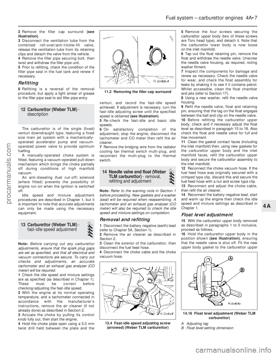
2Remove the filler cap surround (see
illustration) .
3 Disconnect the ventilation tube from the
combined roll-over/anti-trickle-fill valve,
release the ventilation tube from its retaining
clips and detach the valve from the vehicle.
4 Remove the filler pipe securing bolt, then
twist and withdraw the filler pipe unit.
5 Prior to refitting, check the condition of the
filler pipe seal in the fuel tank and renew if
necessary.
Refitting
6 Refitting is a reversal of the removal
procedure, but apply a light smear of grease
to the filler pipe seal to aid filler pipe entry.
12 Carburettor (Weber TLM) -
description
The carburettor is of the single (fixed)
venturi downdraught type, featuring a fixed
size main jet system with a mechanically-
operated accelerator pump and vacuum-
operated power valve to provide optimum
fuelling. A manually-operated choke system is
fitted, featuring a vacuum-operated pull-down
mechanism which brings the choke partially
off during conditions of high manifold
vacuum. An anti-dieseling (fuel cut-off) solenoid
(where fitted) prevents the possibility of
engine run-on when the ignition is switched
off. Idle speed and mixture adjustment
procedures are described in Chapter 1, but it
is important to note that accurate adjustments
can only be made using the necessary
equipment.
13 Carburettor (Weber TLM) -
fast-idle speed adjustment
4
Note: Before carrying out any carburettor
adjustments, ensure that the spark plug gaps
are set as specified, and that all electrical and
vacuum connections are secure. To carry out
checks and adjustments, an accurate
tachometer and an exhaust gas analyser (CO
meter) will be required.
1 Check the idle speed and mixture settings
are as specified (as described in Chapter 1).
These must be correct before
checking/adjusting the fast-idle speed.
2 With the engine at its normal operating
temperature, and a tachometer connected in
accordance with the manufacturer’s
instructions, remove the air cleaner (if not
already done) as described in Section 2.
3 Actuate the choke by pulling its control
knob fully out, then start the engine.
4 Hold the choke plate open using a 5.0 mm
twist drill held between the plate and the venturi, and record the fast-idle speed
achieved. If adjustment is necessary, turn the
fast-idle adjusting screw until the specified
speed is obtained
(see illustration).
5 Re-check the fast-idle and basic idle
speeds.
6 On satisfactory completion of the
adjustment, stop the engine, disconnect the
tachometer and CO meter then refit the air
cleaner.
7 Remove the bridging wire from the radiator
cooling fan thermal switch multi-plug, and
reconnect the multi-plug to the thermal
switch.
14 Needle valve and float (Weber
TLM carburettor) - removal,
refitting and adjustment
4
Note: Refer to the warning note in Section 1
before proceeding. New gaskets and a washer
(seal) will be required when reassembling. A
tachometer and an exhaust gas analyser (CO
meter) will also be required to check the idle
speed and mixture settings on completion.
Removal and refitting
1 Disconnect the battery negative (earth) lead
(refer to Chapter 5A, Section 1).
2 Remove the air cleaner as described in
Section 2.
3 Clean the exterior of the carburettor, then
disconnect the fuel feed hose.
4 Disconnect the choke cable and the choke
vacuum hose. 5
Remove the four screws securing the
carburettor upper body (two of these screws
are Torx head type), and detach it. Note that
the carburettor lower body is now loose
on the inlet manifold.
6 Tap out the float retaining pin, remove the
float and withdraw the needle valve. Unscrew
the needle valve housing, as required, noting
washer fitment.
7 Inspect the components for damage and
renew as necessary. Check the needle valve
for wear, and check the float assembly for
leaks by shaking it to see if it contains petrol.
Whilst accessible, clean the float chamber
and jets (refer to Section 17).
8 Using a new washer, refit the needle valve
housing.
9 Refit the needle valve, float and retaining
pin, ensuring that the tag on the float engages
between the ball and clip on the needle valve.
10 Before refitting the carburettor upper
body, check and if necessary adjust the float
level as described in paragraph 15 to 18. Also
check the float and needle valve for full and
free movement.
11 Clean the gasket contact faces (including
the inlet manifold) then, using new gaskets for
the carburettor upper body and the inlet
manifold faces, refit the carburettor upper
body and secure the carburettor assembly to
the inlet manifold.
12 Reconnect the choke vacuum hose. If the
fuel feed hose was originally secured with a
crimped type clip, discard this and secure the
fuel feed hose with a nut and screw type clip.
13 Reconnect and adjust the choke cable,
then refit the air cleaner.
14 Reconnect the battery negative lead, start
and warm up the engine then check the idle
speed and mixture settings as described in
Chapter 1.
Float level adjustment
15 With the carburettor upper body removed
as described in paragraphs 1 to 5 inclusive,
proceed as follows.
16 Hold the carburettor upper body in the
position shown (see illustration) , ensuring
that the needle valve is shut off. Fit the new
upper body gasket to the carburettor upper
Fuel system – carburettor engines 4A•7
13.4 Fast-idle speed adjusting screw (arrowed) (Weber TLM carburettor)
11.2 Removing the filler cap surround
14.16 Float level adjustment (Weber TLM carburettor)
A Adjusting tag
B Float level setting dimension
4A
1595Ford Fiesta Remakeprocarmanuals.com
http://vnx.su
Page 121 of 296
tachometer and an exhaust gas analyser (CO
meter) will be required.
1Check that the idle speed and mixture
settings are as specified (as described in
Chapter 1). These must be correct before
checking/adjusting the fast-idle speed.
2 Switch the engine off, then remove the air
cleaner as described in Section 2.
3 With the engine at its normal operating
temperature and a tachometer connected in
accordance with its manufacturer’s
instructions, hold the throttle linkage partly
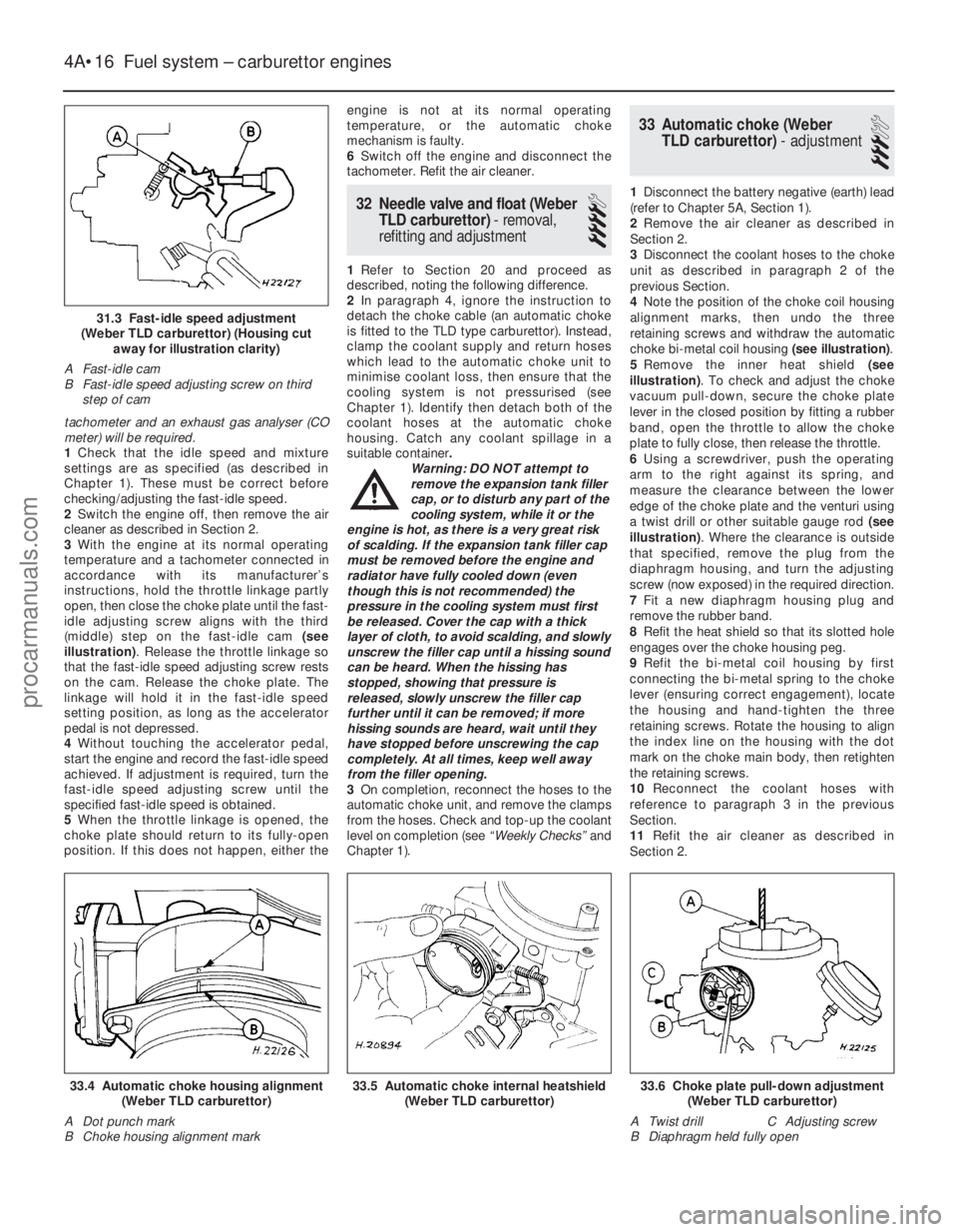
open, then close the choke plate until the fast-
idle adjusting screw aligns with the third
(middle) step on the fast-idle cam (see
illustration) . Release the throttle linkage so
that the fast-idle speed adjusting screw rests
on the cam. Release the choke plate. The
linkage will hold it in the fast-idle speed
setting position, as long as the accelerator
pedal is not depressed.
4 Without touching the accelerator pedal,
start the engine and record the fast-idle speed
achieved. If adjustment is required, turn the
fast-idle speed adjusting screw until the
specified fast-idle speed is obtained.
5 When the throttle linkage is opened, the
choke plate should return to its fully-open
position. If this does not happen, either the engine is not at its normal operating
temperature, or the automatic choke
mechanism is faulty.
6
Switch off the engine and disconnect the
tachometer. Refit the air cleaner.
32 Needle valve and float (Weber
TLD carburettor) - removal,
refitting and adjustment
4
1 Refer to Section 20 and proceed as
described, noting the following difference.
2 In paragraph 4, ignore the instruction to
detach the choke cable (an automatic choke
is fitted to the TLD type carburettor). Instead,
clamp the coolant supply and return hoses
which lead to the automatic choke unit to
minimise coolant loss, then ensure that the
cooling system is not pressurised (see
Chapter 1). Identify then detach both of the
coolant hoses at the automatic choke
housing. Catch any coolant spillage in a
suitable container .
Warning: DO NOT attempt to
remove the expansion tank filler
cap, or to disturb any part of the
cooling system, while it or the
engine is hot, as there is a very great risk
of scalding. If the expansion tank filler cap
must be removed before the engine and
radiator have fully cooled down (even
though this is not recommended) the
pressure in the cooling system must first
be released. Cover the cap with a thick
layer of cloth, to avoid scalding, and slowly
unscrew the filler cap until a hissing sound
can be heard. When the hissing has
stopped, showing that pressure is
released, slowly unscrew the filler cap
further until it can be removed; if more
hissing sounds are heard, wait until they
have stopped before unscrewing the cap
completely. At all times, keep well away
from the filler opening.
3 On completion, reconnect the hoses to the
automatic choke unit, and remove the clamps
from the hoses. Check and top-up the coolant
level on completion (see “Weekly Checks”and
Chapter 1).
33 Automatic choke (Weber TLD carburettor) - adjustment
3
1Disconnect the battery negative (earth) lead
(refer to Chapter 5A, Section 1).
2 Remove the air cleaner as described in
Section 2.
3 Disconnect the coolant hoses to the choke
unit as described in paragraph 2 of the
previous Section.
4 Note the position of the choke coil housing
alignment marks, then undo the three
retaining screws and withdraw the automatic
choke bi-metal coil housing (see illustration).
5 Remove the inner heat shield (see
illustration) . To check and adjust the choke
vacuum pull-down, secure the choke plate
lever in the closed position by fitting a rubber
band, open the throttle to allow the choke
plate to fully close, then release the throttle.
6 Using a screwdriver, push the operating
arm to the right against its spring, and
measure the clearance between the lower
edge of the choke plate and the venturi using
a twist drill or other suitable gauge rod (see
illustration) . Where the clearance is outside
that specified, remove the plug from the
diaphragm housing, and turn the adjusting
screw (now exposed) in the required direction.
7 Fit a new diaphragm housing plug and
remove the rubber band.
8 Refit the heat shield so that its slotted hole
engages over the choke housing peg.
9 Refit the bi-metal coil housing by first
connecting the bi-metal spring to the choke
lever (ensuring correct engagement), locate
the housing and hand-tighten the three
retaining screws. Rotate the housing to align
the index line on the housing with the dot
mark on the choke main body, then retighten
the retaining screws.
10 Reconnect the coolant hoses with
reference to paragraph 3 in the previous
Section.
11 Refit the air cleaner as described in
Section 2.
4A•16 Fuel system – carburettor engines
33.6 Choke plate pull-down adjustment (Weber TLD carburettor)
A Twist drill C Adjusting screw
B Diaphragm held fully open33.5 Automatic choke internal heatshield (Weber TLD carburettor)33.4 Automatic choke housing alignment(Weber TLD carburettor)
A Dot punch mark
B Choke housing alignment mark
1595Ford Fiesta Remake
31.3 Fast-idle speed adjustment
(Weber TLD carburettor) (Housing cut away for illustration clarity)
A Fast-idle cam
B Fast-idle speed adjusting screw on third step of cam
procarmanuals.com
http://vnx.su
Page 122 of 296
34 Automatic choke (WeberTLD carburettor) - removal,
inspection and refitting
4
Note: Refer to the warning note in Section 1
before proceeding. A new carburettor upper
body gasket will be required when
reassembling. On completion, a tachometer
will be required to check the fast-idle speed
adjustment.
Removal
1 Disconnect the battery negative (earth) lead
(refer to Chapter 5A, Section 1).
2 Remove the air cleaner as described in
Section 2.
3 To prevent excess coolant loss, clamp the
coolant supply and return hoses to the
automatic choke unit, and ensure that the
cooling system is not pressurised (see
Chapter 1). Identify then detach both of the
coolant hoses at the automatic choke
housing. Catch any coolant spillage in a
suitable container.
Warning: DO NOT attempt to
remove the expansion tank filler
cap, or to disturb any part of the
cooling system, while it or the
engine is hot, as there is a very great risk
of scalding. If the expansion tank filler cap
must be removed before the engine and
radiator have fully cooled down (even
though this is not recommended) the
pressure in the cooling system must first
be released. Cover the cap with a thick
layer of cloth, to avoid scalding, and slowly
unscrew the filler cap until a hissing sound
can be heard. When the hissing has
stopped, showing that pressure is
released, slowly unscrew the filler cap
further until it can be removed; if more
hissing sounds are heard, wait until they
have stopped before unscrewing the cap
completely. At all times, keep well away
from the filler opening.
4 Detach the fuel pipe and the anti-dieseling
solenoid wiring connector. Any crimped type
hose clips must be replaced with a screw
clamp type clips during reassembly.
5 Unscrew and remove the retaining screws (two conventional, and four Torx type), then lift
the carburettor upper body clear and remove it.
6
Note the position of the choke housing
alignment marks, then undo the three retaining
screws and remove the choke bi-metal coil
unit. Remove the internal heat shield.
7 To remove the automatic choke unit, undo
the three retaining screws and detach the
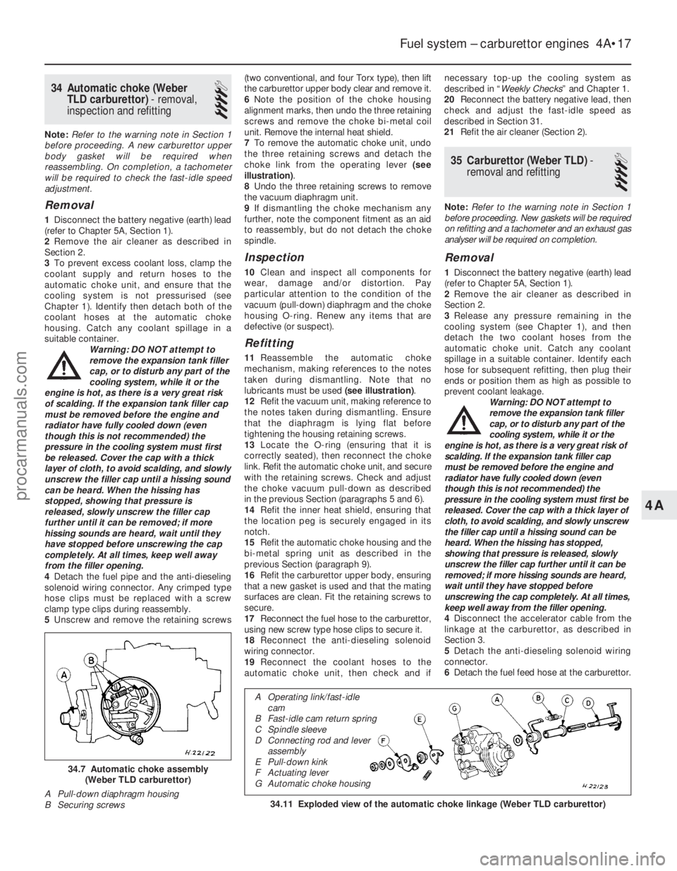
choke link from the operating lever (see
illustration) .
8 Undo the three retaining screws to remove
the vacuum diaphragm unit.
9 If dismantling the choke mechanism any
further, note the component fitment as an aid
to reassembly, but do not detach the choke
spindle.
Inspection
10 Clean and inspect all components for
wear, damage and/or distortion. Pay
particular attention to the condition of the
vacuum (pull-down) diaphragm and the choke
housing O-ring. Renew any items that are
defective (or suspect).
Refitting
11 Reassemble the automatic choke
mechanism, making references to the notes
taken during dismantling. Note that no
lubricants must be used (see illustration).
12 Refit the vacuum unit, making reference to
the notes taken during dismantling. Ensure
that the diaphragm is lying flat before
tightening the housing retaining screws.
13 Locate the O-ring (ensuring that it is
correctly seated), then reconnect the choke
link. Refit the automatic choke unit, and secure
with the retaining screws. Check and adjust
the choke vacuum pull-down as described
in the previous Section (paragraphs 5 and 6).
14 Refit the inner heat shield, ensuring that
the location peg is securely engaged in its
notch.
15 Refit the automatic choke housing and the
bi-metal spring unit as described in the
previous Section (paragraph 9).
16 Refit the carburettor upper body, ensuring
that a new gasket is used and that the mating
surfaces are clean. Fit the retaining screws to
secure.
17 Reconnect the fuel hose to the carburettor,
using new screw type hose clips to secure it.
18 Reconnect the anti-dieseling solenoid
wiring connector.
19 Reconnect the coolant hoses to the
automatic choke unit, then check and if necessary top-up the cooling system as
described in “
Weekly Checks ” and Chapter 1.
20 Reconnect the battery negative lead, then
check and adjust the fast-idle speed as
described in Section 31.
21 Refit the air cleaner (Section 2).
35 Carburettor (Weber TLD) -
removal and refitting
4
Note: Refer to the warning note in Section 1
before proceeding. New gaskets will be required
on refitting and a tachometer and an exhaust gas
analyser will be required on completion.
Removal
1 Disconnect the battery negative (earth) lead
(refer to Chapter 5A, Section 1).
2 Remove the air cleaner as described in
Section 2.
3 Release any pressure remaining in the
cooling system (see Chapter 1), and then
detach the two coolant hoses from the
automatic choke unit. Catch any coolant
spillage in a suitable container. Identify each
hose for subsequent refitting, then plug their
ends or position them as high as possible to
prevent coolant leakage. Warning: DO NOT attempt to
remove the expansion tank filler
cap, or to disturb any part of the
cooling system, while it or the
engine is hot, as there is a very great risk of
scalding. If the expansion tank filler cap
must be removed before the engine and
radiator have fully cooled down (even
though this is not recommended) the
pressure in the cooling system must first be
released. Cover the cap with a thick layer of
cloth, to avoid scalding, and slowly unscrew
the filler cap until a hissing sound can be
heard. When the hissing has stopped,
showing that pressure is released, slowly
unscrew the filler cap further until it can be
removed; if more hissing sounds are heard,
wait until they have stopped before
unscrewing the cap completely. At all times,
keep well away from the filler opening.
4 Disconnect the accelerator cable from the
linkage at the carburettor, as described in
Section 3.
5 Detach the anti-dieseling solenoid wiring
connector.
6 Detach the fuel feed hose at the carburettor.
Fuel system – carburettor engines 4A•17
34.11 Exploded view of the automatic choke linkage (Weber TLD carburet\
tor)
34.7 Automatic choke assembly
(Weber TLD carburettor)
A Pull-down diaphragm housing
B Securing screws
4A
1595Ford Fiesta Remake
A Operating link/fast-idle cam
B Fast-idle cam return spring
C Spindle sleeve
D Connecting rod and lever assembly
E Pull-down kink
F Actuating lever
G Automatic choke housing
procarmanuals.com
http://vnx.su
Page 126 of 296
This is used to refine the calculations made by
the module, when determining the correct
amount of fuel required to achieve the ideal
air/fuel mixture ratio.A throttle position sensor is mounted on the
end of the throttle valve spindle, to provide
the EEC IV module with a constantly-varying
(analogue) voltage signal corresponding to the
throttle opening. This allows the module to
register the driver’s input when determining
the amount of fuel required by the engine. Road speed is monitored by the vehicle
speed sensor. This component is a Hall-effect
generator, mounted on the transmission’s
speedometer drive. It supplies the EEC IV
module with a series of pulses corresponding
to the vehicle’s road speed, enabling the
module to control features such as the fuel
shut-off on overrun. A manifold absolute pressure sensor
measures inlet manifold vacuum, and supplies
this information to the module for calculation
of engine load at any given throttle position. Where power steering is fitted, a pressure-
operated switch is screwed into the power
steering system’s high-pressure pipe. The
switch sends a signal to the EEC IV module to
reduce engine speed should the power
steering fluid pressure become excessively
high. Certain later engines may be fitted with a
heater in the inlet manifold. This is controlled
by the EEC IV module to ensure that, even
before the effect of the coolant heating
becomes apparent, the manifold is warmed-
up. This prevents fuel droplets condensing in
the manifold, thus improving driveability and
reducing exhaust emissions when the engine
is cold.
The oxygen sensor in the exhaust system
provides the EEC IV module with constant
feedback - “closed-loop” control - which
enables it to adjust the mixture to provide the
best possible conditions for the catalytic
converter to operate.
Precautions
Warning: Petrol is extremely
flammable - great care must be
taken when working on any part
of the fuel system. Do not
smoke or allow any naked flames or
uncovered light bulbs near the work area.
Note that gas powered domestic
appliances with pilot flames, such as
heaters, boilers and tumble dryers, also
present a fire hazard - bear this in mind if
you are working in an area where such
appliances are present. Always keep a
suitable fire extinguisher close to the work
area and familiarise yourself with its
operation before starting work. Wear eye
protection when working on fuel systems
and wash off any fuel spilt on bare skin
immediately with soap and water. Note
that fuel vapour is just as dangerous as
liquid fuel; a vessel that has just been
emptied of liquid fuel will still contain vapour and can be potentially explosive.
Petrol is a highly dangerous and volatile
liquid, and the precautions necessary
when handling it cannot be overstressed.
Many of the operations described in this
Chapter involve the disconnection of fuel
lines, which may cause an amount of fuel
spillage. Before commencing work, refer
to the above Warning and the information
in “Safety first” at the beginning of this
manual. When working with fuel system
components, pay particular attention to
cleanliness - dirt entering the fuel system
may cause blockages which will lead to
poor running.
Note: Residual pressure will remain in the fuel
lines long after the vehicle was last used,
when disconnecting any fuel line, it will be
necessary to depressurise the fuel system as
described in Section 2 .
2 Fuel system-
depressurisation
1
Note: Refer to the warning note in Section 1
before proceeding.
Warning: The following
procedure will merely relieve the
pressure in the fuel system -
remember that fuel will still be present in
the system components, and take
precautions accordingly before
disconnecting any of them.
1 The fuel system referred to in this Chapter
is defined as the fuel tank and tank-mounted
fuel pump/fuel gauge sender unit, the fuel
filter, the fuel injector, fuel pressure regulator,
and the metal pipes and flexible hoses of the
fuel lines between these components. All
these contain fuel, which will be under
pressure while the engine is running and/or
while the ignition is switched on.
2 The pressure will remain for some time after
the ignition has been switched off, and must
be relieved before any of these components is
disturbed for servicing work.
3 The simplest depressurisation method is to
disconnect the fuel pump electrical supply by
removing the fuel pump fuse (No 19) and
starting the engine; allow the engine to idle
until it dies through lack of fuel pressure. Turn
the engine over once or twice on the starter to
ensure that all pressure is released, then
switch off the ignition; do not forget to refit the
fuse when work is complete.
4 Note that, once the fuel system has been
depressurised and drained (even partially), it
will take significantly longer to restart the
engine - perhaps several seconds of cranking
- before the system is refilled and pressure
restored.
3 Fuel lines and fittings -
general information
Note: Refer to the warning note in Section 1
before proceeding.
Disconnecting and connecting
quick-release couplings
1 Quick-release couplings are employed at
many of the unions in the fuel feed and return
lines.
2 Before disconnecting any fuel system
component, relieve the residual pressure in
the system (see Section 2), and equalise tank
pressure by removing the fuel filler cap.
Warning: This procedure will
merely relieve the increased
pressure necessary for the
engine to run - remember that
fuel will still be present in the system
components, and take precautions
accordingly before disconnecting any of
them.
3 Release the protruding locking lugs on each
union, by squeezing them together and
carefully pulling the coupling apart. Use rag to
soak up any spilt fuel. Where the unions are
colour-coded, the pipes cannot be confused.
Where both unions are the same colour, note
carefully which pipe is connected to which,
and ensure that they are correctly
reconnected on refitting.
4 To reconnect one of these couplings, press
them together until the locking lugs snap into
their groove. Switch the ignition on and off
five times to pressurise the system, and check
for any sign of fuel leakage around the
disturbed coupling before attempting to start
the engine.
Checking
5 Checking procedures for the fuel lines are
included in Chapter 1.
Component renewal
6 If any damaged sections are to be renewed,
use original-equipment replacement hoses or
pipes, constructed from exactly the same
material as the section being replaced. Do not
install substitutes constructed from inferior or
inappropriate material; this could cause a fuel
leak or a fire.
7 Before detaching or disconnecting any part
of the fuel system, note the routing of all
hoses and pipes, and the orientation of all
clamps and clips. Replacement sections must
be installed in exactly the same manner.
8 Before disconnecting any part of the fuel
system, be sure to relieve the fuel system
pressure (see Section 2), and equalise tank
pressure by removing the fuel filler cap. Also
disconnect the battery negative (earth) lead -
see Chapter 5A, Section 1. Cover the fitting
being disconnected with a rag, to absorb any
fuel that may spray out.
Fuel system - central fuel injection engines 4B•3
4B
1595Ford Fiesta Remakeprocarmanuals.com
http://vnx.su
Page 127 of 296
4 Air cleaner assembly and airinlet components -
removal and refitting
1
Note: Air cleaner element renewal and air
cleaner temperature control system checks
(where applicable) are described in Chapter 1.
Air cleaner assembly
1 Disconnect the battery negative (earth) lead
(refer to Chapter 5A, Section 1).
2 Undo the retaining bolts and partially lift the
air cleaner from the CFi unit, so that the hose
and wiring connections to the underside of
the air cleaner body are accessible.
3 Note their connections and routings, then
detach the wiring and hoses from the
underside of the air cleaner.
4 Lift the air cleaner clear from the CFi unit.
5 Refit in the reverse order of removal.
6 Renew any hoses that are perished or
cracked, and ensure that all fittings are
securely and correctly reconnected.
Air inlet components
7 The air cleaner inlet spout and related
components are removed with the air cleaner
assembly as described above.
5 Accelerator cable - removal,
refitting and adjustment
1
Removal
1 Disconnect the battery negative (earth) lead
(refer to Chapter 5A, Section 1).
2 Fold back the carpet and insulation in the
driver’s footwell to gain access to the
accelerator pedal.
3 Detach the accelerator cable from the
pedal.
4 Remove the air cleaner assembly as
described in Section 4.
5 Working at the throttle housing end of the
cable, pivot the throttle quadrant by hand to
release the tension from the cable, then
detach the inner cable nipple from the throttle
lever.
6 Detach the outer cable from the
adjuster/support bracket, then remove the
cable.
Refitting and adjustment
7 Refit in the reverse order of removal. When
the cable is reconnected at each end, have an
assistant depress the accelerator, and check
that the throttle fully opens and shuts without
binding. Ensure that there is a small amount of
slack in the inner cable when the throttle is
fully released. If adjustment is required,
release the outer cable retaining clip from the
cable at the adjustment/support bracket, slide
the cable through the adjuster grommet to the
point required, then refit the retaining clip to
secure it in the set position.
6 Accelerator pedal -
removal and refitting
1
Refer to Part A, Section 5.
7 Fuel pump/fuel pressure -
checking
3
Note: Refer to the warning note in Section 1
before proceeding.
Fuel pump operation check
1 Switch on the ignition, and listen for the fuel
pump (the sound of an electric motor running,
audible from beneath the rear seats). Assuming
there is sufficient fuel in the tank, the pump
should start and run for approximately one or
two seconds, then stop, each time the ignition
is switched on. Note:If the pump runs
continuously all the time the ignition is switched
on, the electronic control system is running in
the backup (or “limp-home”) mode referred to
by Ford as “Limited Operation Strategy” (LOS).
This almost certainly indicates a fault in the
EEC IV module itself, and the vehicle should
therefore be taken to a Ford dealer for a full test
of the complete system, using the correct
diagnostic equipment; do not waste time or risk
damaging the components by trying to test the
system without such facilities.
2 Listen for fuel return noises from the fuel
pressure regulator. It should be possible to
feel the fuel pulsing in the regulator and in the
feed hose from the fuel filter.
3 If the pump does not run at all, check the
fuse, relay and wiring (see Chapter 12). Check
also that the fuel cut-off switch has not been
activated and if so, reset it.
Fuel pressure check
4 A fuel pressure gauge will be required for this
check and should be connected in the fuel line
between the fuel filter and the CFi unit, in
accordance with the gauge maker’s instructions.
5 Start the engine and allow it to idle. Note
the gauge reading as soon as the pressure
stabilises, and compare it with the figures
given for regulated fuel pressure in the
Specifications . If the pressure is high, check
for a restricted fuel return line. If the pressure
is low, renew the fuel pressure regulator. 6
Switch off the engine, and check that after
one minute, the hold pressure has not fallen
below that specified. If it has, check the seals
on the fuel injector (see Section 14) and renew
them if they appear in any way suspect. If the
seals are okay, then the fuel pressure
regulator or CFi unit are suspect.
7 Carefully disconnect the fuel pressure
gauge, depressurising the system first as
described in Section 2.
8 Run the engine, and check that there are no
fuel leaks.
8 Fuel tank - removal,
inspection and refitting
3
Proceed as described in Part A, Section 8, but
before disconnecting the battery, relieve the
residual pressure in the fuel system (see Sec-
tion 2), and equalise tank pressure by removing
the fuel filler cap. Note also that it will be
necessary to release any additional ventilation
tubes from their retaining clips, and to reposition
or remove the underbody heat shields on certain
models for access to the tank retaining bolts.
9 Fuel pump/fuel gauge
sender unit - removal and
refitting
3
Note: Refer to the warning note in Section 1
before proceeding. Ford specify the use of their
service tool 23-026 (a large box spanner with
projecting teeth to engage the fuel pump/sender
unit retaining ring’s slots) for this task. While
alternatives are possible, in view of the difficulty
experienced in removing and refitting the
pump/sender unit, it is strongly advised that the
correct tool is obtained before starting work.
Removal
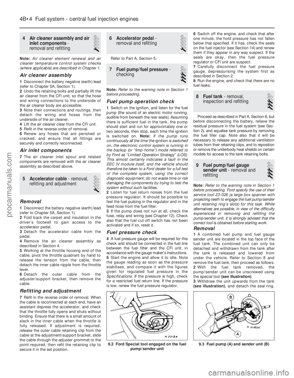
1 A combined fuel pump and fuel gauge
sender unit are located in the top face of the
fuel tank. The combined unit can only be
detached and withdrawn from the tank after
the tank is released and lowered from
under the vehicle. Refer to Section 8 and
remove the fuel tank, then proceed as follows.
2 With the fuel tank removed, the
pump/sender unit can be unscrewed using
the special tool (see illustration) .
3 Withdraw the unit upwards from the tank
(see illustration) , and detach the seal ring.
9.3 Fuel pump (A) and sender unit (B)
4B•4 Fuel system - central fuel injection engines
9.2 Ford Special tool engaged on the fuel
pump/sender unit
1595Ford Fiesta Remakeprocarmanuals.com
http://vnx.su
Page 128 of 296
The seal ring must be renewed whenever the
pump/sender unit is withdrawn from the tank.
Refitting
4Refit in the reverse order of removal. Lightly
coat the new unit seal ring with grease to ease
fitting, and ensure that the seal is not
distorted as the unit is fitted into position.
Insert the unit so that the lug of the unit is in
engagement with the slot in the tank aperture,
then turn the unit to lock and secure.
10 Fuel tank ventilation tube -
removal and refitting
3
Refer to Part A, Section 10, but note that on
models with evaporative emission control, the
ventilation tube connects to the combined
roll-over/anti-trickle-fill valve assembly but,
instead of venting to atmosphere, a further
tube runs the length of the vehicle to a carbon
canister in the front right-hand corner of the
engine compartment. Further information on the evaporative
emission control system is contained in Part E
of this Chapter.
11 Fuel tank filler pipe -
removal and refitting
3
Refer to Part A, Section 11.
12 Fuel cut-off switch -
removal and refitting
2
Removal
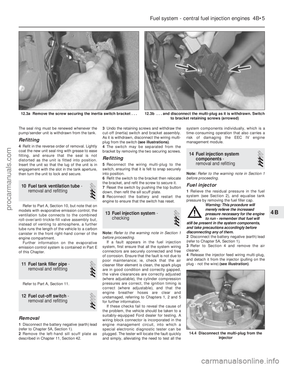
1 Disconnect the battery negative (earth) lead
(refer to Chapter 5A, Section 1).
2 Remove the left-hand sill scuff plate as
described in Chapter 11, Section 42. 3
Undo the retaining screws and withdraw the
cut-off (inertia) switch and bracket assembly.
As it is withdrawn, disconnect the wiring multi-
plug from the switch (see illustrations).
4 The switch may be separated from the
bracket by removing the two securing screws.
Refitting
5 Reconnect the wiring multi-plug to the
switch, ensuring that it is felt to snap securely
into position.
6 Refit the switch to the bracket then relocate
the bracket, and refit the screw to secure it.
7 Reset the switch by pushing the top button
down, then refit the sill scuff plate.
8 Reconnect the battery and restart the
engine to ensure that the switch has reset.
13 Fuel injection system -
checking
3
Note: Refer to the warning note in Section 1
before proceeding. If a fault appears in the fuel injection
system, first ensure that all the system wiring
connectors are securely connected and free
of corrosion. Ensure that the fault is not due to
poor maintenance; ie, check that the air
cleaner filter element is clean, the spark plugs
are in good condition and correctly gapped,
the valve clearances are correctly adjusted
(where adjustable), the cylinder compression
pressures are correct, the ignition timing is
correct (where adjustable), and that the
engine breather hoses are clear and
undamaged, referring to Chapters 1, 2 and 5
for further information. If these checks fail to reveal the cause of
the problem, the vehicle should be taken to a
suitably-equipped Ford dealer for testing. A
wiring block connector is incorporated in the
engine management circuit, into which a
special electronic diagnostic tester can be
plugged. The tester will locate the fault quickly
and simply, alleviating the need to test all the system components individually, which is a
time-consuming operation that also carries a
risk of damaging the EEC IV engine
management module.
14 Fuel injection system
components -
removal and refitting
3
Note: Refer to the warning note in Section 1
before proceeding.
Fuel injector
1 Relieve the residual pressure in the fuel
system (see Section 2), and equalise tank
pressure by removing the fuel filler cap.
Warning: This procedure will
merely relieve the increased
pressure necessary for the engine
to run - remember that fuel will
still be present in the system components,
and take precautions accordingly before
disconnecting any of them.
2 Disconnect the battery negative (earth) lead
(refer to Chapter 5A, Section 1).
3 Refer to Section 4 and remove the air
cleaner.
4 Release the injector feed wiring multi-plug,
and detach it from the injector (pulling on the
plug - not the wire) (see illustration).
Fuel system - central fuel injection engines 4B•5
12.3b . . . and disconnect the multi-plug as it is withdrawn. Switch
to bracket retaining screws (arrowed)12.3a Remove the screw securing the inertia switch bracket . . .
14.4 Disconnect the multi-plug from the injector
4B
1595Ford Fiesta Remakeprocarmanuals.com
http://vnx.su
Page 129 of 296
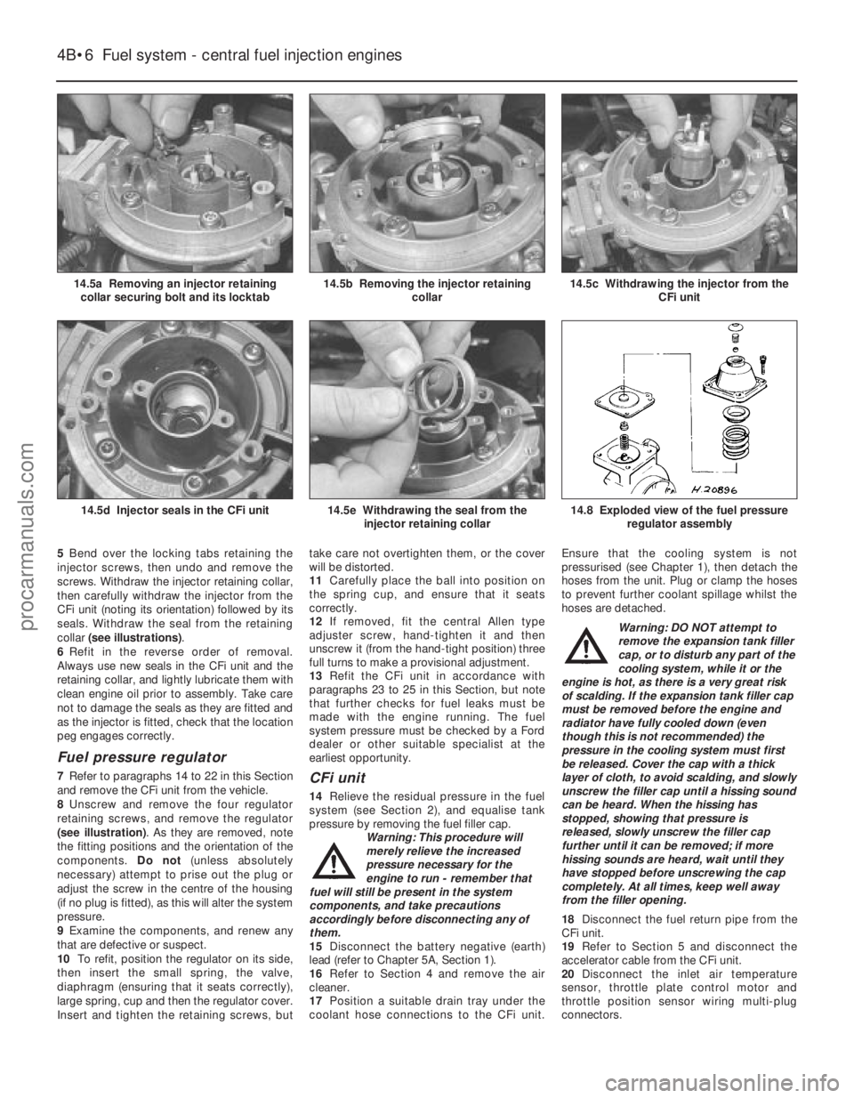
5Bend over the locking tabs retaining the
injector screws, then undo and remove the
screws. Withdraw the injector retaining collar,
then carefully withdraw the injector from the
CFi unit (noting its orientation) followed by its
seals. Withdraw the seal from the retaining
collar (see illustrations) .
6 Refit in the reverse order of removal.
Always use new seals in the CFi unit and the
retaining collar, and lightly lubricate them with
clean engine oil prior to assembly. Take care
not to damage the seals as they are fitted and
as the injector is fitted, check that the location
peg engages correctly.
Fuel pressure regulator
7 Refer to paragraphs 14 to 22 in this Section
and remove the CFi unit from the vehicle.
8 Unscrew and remove the four regulator
retaining screws, and remove the regulator
(see illustration) . As they are removed, note
the fitting positions and the orientation of the
components. Do not(unless absolutely
necessary) attempt to prise out the plug or
adjust the screw in the centre of the housing
(if no plug is fitted), as this will alter the system
pressure.
9 Examine the components, and renew any
that are defective or suspect.
10 To refit, position the regulator on its side,
then insert the small spring, the valve,
diaphragm (ensuring that it seats correctly),
large spring, cup and then the regulator cover.
Insert and tighten the retaining screws, but take care not overtighten them, or the cover
will be distorted.
11
Carefully place the ball into position on
the spring cup, and ensure that it seats
correctly.
12 If removed, fit the central Allen type
adjuster screw, hand-tighten it and then
unscrew it (from the hand-tight position) three
full turns to make a provisional adjustment.
13 Refit the CFi unit in accordance with
paragraphs 23 to 25 in this Section, but note
that further checks for fuel leaks must be
made with the engine running. The fuel
system pressure must be checked by a Ford
dealer or other suitable specialist at the
earliest opportunity.CFi unit
14 Relieve the residual pressure in the fuel
system (see Section 2), and equalise tank
pressure by removing the fuel filler cap. Warning: This procedure will
merely relieve the increased
pressure necessary for the
engine to run - remember that
fuel will still be present in the system
components, and take precautions
accordingly before disconnecting any of
them.
15 Disconnect the battery negative (earth)
lead (refer to Chapter 5A, Section 1).
16 Refer to Section 4 and remove the air
cleaner.
17 Position a suitable drain tray under the
coolant hose connections to the CFi unit. Ensure that the cooling system is not
pressurised (see Chapter 1), then detach the
hoses from the unit. Plug or clamp the hoses
to prevent further coolant spillage whilst the
hoses are detached.
Warning: DO NOT attempt to
remove the expansion tank filler
cap, or to disturb any part of the
cooling system, while it or the
engine is hot, as there is a very great risk
of scalding. If the expansion tank filler cap
must be removed before the engine and
radiator have fully cooled down (even
though this is not recommended) the
pressure in the cooling system must first
be released. Cover the cap with a thick
layer of cloth, to avoid scalding, and slowly
unscrew the filler cap until a hissing sound
can be heard. When the hissing has
stopped, showing that pressure is
released, slowly unscrew the filler cap
further until it can be removed; if more
hissing sounds are heard, wait until they
have stopped before unscrewing the cap
completely. At all times, keep well away
from the filler opening.
18 Disconnect the fuel return pipe from the
CFi unit.
19 Refer to Section 5 and disconnect the
accelerator cable from the CFi unit.
20 Disconnect the inlet air temperature
sensor, throttle plate control motor and
throttle position sensor wiring multi-plug
connectors.
4B•6 Fuel system - central fuel injection engines
14.8 Exploded view of the fuel pressure
regulator assembly14.5e Withdrawing the seal from theinjector retaining collar14.5d Injector seals in the CFi unit
14.5c Withdrawing the injector from the CFi unit14.5b Removing the injector retainingcollar14.5a Removing an injector retainingcollar securing bolt and its locktab
1595Ford Fiesta Remakeprocarmanuals.com
http://vnx.su
Page 138 of 296
8 Fuel tank- removal,
inspection and refitting
3
Proceed as described in Part A, Section 8,
but before disconnecting the battery, relieve
the residual pressure in the fuel system (see
Section 2), and equalise tank pressure by
removing the fuel filler cap.
9 Fuel pump/fuel gauge sender unit - removal and
refitting
3
Refer to Part B, Section 9.
10 Fuel tank ventilation tube -
removal and refitting
3
Refer to Part A, Section 10, but note that on
models with evaporative emission control, the
ventilation tube connects to the combined
roll-over/anti-trickle-fill valve assembly but,
instead of venting to atmosphere, a further
tube runs the length of the vehicle to a carbon
canister in the front right-hand corner of the
engine compartment.
Further information on the evaporative
emission control system is contained in Part E
of this Chapter.
11 Fuel tank filler pipe -
removal and refitting
3
Refer to Part A, Section 11.
12 Fuel cut-off switch -
removal and refitting
1
Refer to Part B, Section 12.
13 Fuel injection system -
checking
3
Refer to Part B, Section 13
14 Fuel injection system components - removal and
refitting
3
Note: Refer to the warning note in Section 1
before proceeding.
Fuel rail and injectors
Note: For simplicity, and to ensure that the
necessary absolute cleanliness on reassembly,
the following procedure describes the removal
of the fuel rail assembly, complete with the
injectors and pressure regulator, so that
the injectors can be serviced individually on a clean work surface. It is also possible to remove
and refit an individual injector, once the fuel
system has been depressurised and the battery
has been disconnected. If this approach is
followed, read through the complete
procedure, and work as described in the
relevant paragraphs, depending on the amount
of preliminary dismantling required. Be careful
not to allow any dirt to enter the system.
1
Relieve the residual pressure in the fuel
system (see Section 2), and equalise tank
pressure by removing the fuel filler cap. Warning: This procedure will
merely relieve the increased
pressure necessary for the engine
to run - remember that fuel will
still be present in the system components,
and take precautions accordingly before
disconnecting any of them.
2 Disconnect the battery negative (earth) lead
(refer to Chapter 5A, Section 1).
3 Disconnect the HT lead connectors from the
spark plugs, and release the leads from their
locating grooves in the air inlet duct. Position
them out of the way. On Turbo models, undo the
two screws and remove the HT lead bracket.
4 Remove the air inlet components as
described in Section 4.
5 Unscrew the retaining nuts and the bolt,
and detach the accelerator cable support
bracket at the throttle housing.
6 Disconnect the wiring connector from the
throttle position sensor.
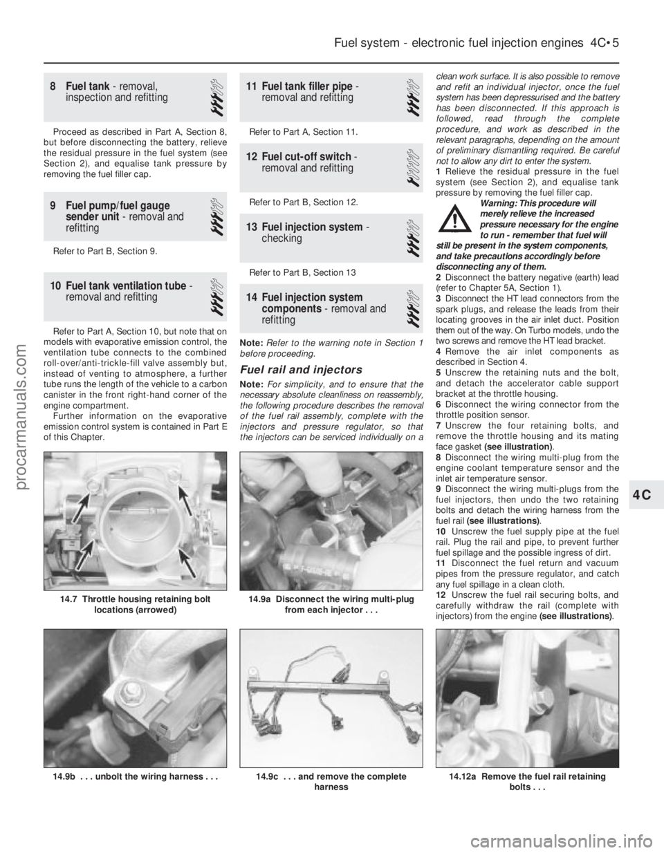
7 Unscrew the four retaining bolts, and
remove the throttle housing and its mating
face gasket (see illustration) .
8 Disconnect the wiring multi-plug from the
engine coolant temperature sensor and the
inlet air temperature sensor.
9 Disconnect the wiring multi-plugs from the
fuel injectors, then undo the two retaining
bolts and detach the wiring harness from the
fuel rail (see illustrations) .
10 Unscrew the fuel supply pipe at the fuel
rail. Plug the rail and pipe, to prevent further
fuel spillage and the possible ingress of dirt.
11 Disconnect the fuel return and vacuum
pipes from the pressure regulator, and catch
any fuel spillage in a clean cloth.
12 Unscrew the fuel rail securing bolts, and
carefully withdraw the rail (complete with
injectors) from the engine (see illustrations).
Fuel system - electronic fuel injection engines 4C•5
14.9b . . . unbolt the wiring harness . . .
14.9a Disconnect the wiring multi-plug
from each injector . . .14.7 Throttle housing retaining boltlocations (arrowed)
4C
1595Ford Fiesta Remake 14.12a Remove the fuel rail retaining
bolts . . .
14.9c . . . and remove the completeharness
procarmanuals.com
http://vnx.su
Page 139 of 296
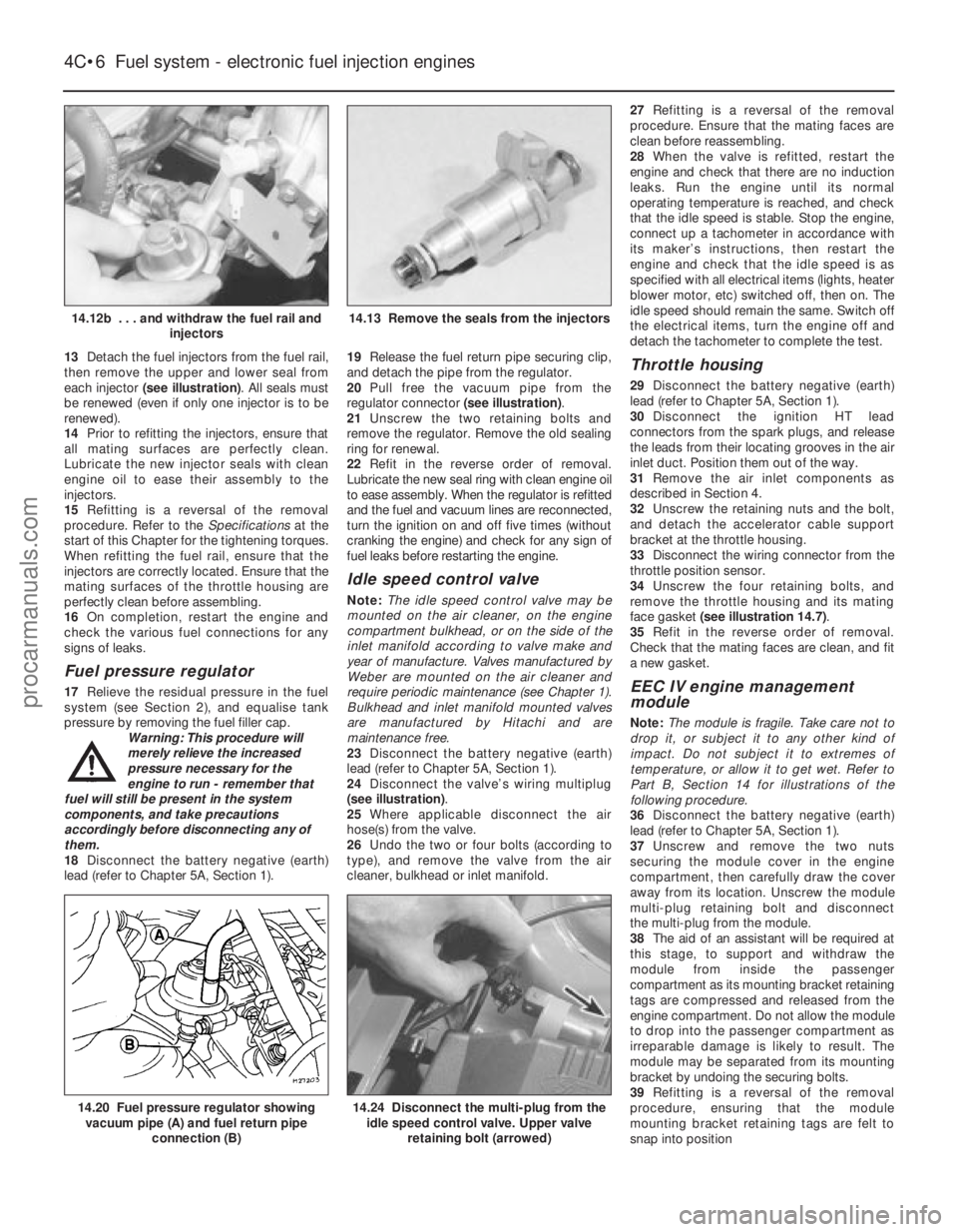
13Detach the fuel injectors from the fuel rail,
then remove the upper and lower seal from
each injector (see illustration) . All seals must
be renewed (even if only one injector is to be
renewed).
14 Prior to refitting the injectors, ensure that
all mating surfaces are perfectly clean.
Lubricate the new injector seals with clean
engine oil to ease their assembly to the
injectors.
15 Refitting is a reversal of the removal
procedure. Refer to the Specificationsat the
start of this Chapter for the tightening torques.
When refitting the fuel rail, ensure that the
injectors are correctly located. Ensure that the
mating surfaces of the throttle housing are
perfectly clean before assembling.
16 On completion, restart the engine and
check the various fuel connections for any
signs of leaks.
Fuel pressure regulator
17 Relieve the residual pressure in the fuel
system (see Section 2), and equalise tank
pressure by removing the fuel filler cap. Warning: This procedure will
merely relieve the increased
pressure necessary for the
engine to run - remember that
fuel will still be present in the system
components, and take precautions
accordingly before disconnecting any of
them.
18 Disconnect the battery negative (earth)
lead (refer to Chapter 5A, Section 1). 19
Release the fuel return pipe securing clip,
and detach the pipe from the regulator.
20 Pull free the vacuum pipe from the
regulator connector (see illustration).
21 Unscrew the two retaining bolts and
remove the regulator. Remove the old sealing
ring for renewal.
22 Refit in the reverse order of removal.
Lubricate the new seal ring with clean engine oil
to ease assembly. When the regulator is refitted
and the fuel and vacuum lines are reconnected,
turn the ignition on and off five times (without
cranking the engine) and check for any sign of
fuel leaks before restarting the engine.
Idle speed control valve
Note: The idle speed control valve may be
mounted on the air cleaner, on the engine
compartment bulkhead, or on the side of the
inlet manifold according to valve make and
year of manufacture. Valves manufactured by
Weber are mounted on the air cleaner and
require periodic maintenance (see Chapter 1).
Bulkhead and inlet manifold mounted valves
are manufactured by Hitachi and are
maintenance free.
23 Disconnect the battery negative (earth)
lead (refer to Chapter 5A, Section 1).
24 Disconnect the valve’s wiring multiplug
(see illustration) .
25 Where applicable disconnect the air
hose(s) from the valve.
26 Undo the two or four bolts (according to
type), and remove the valve from the air
cleaner, bulkhead or inlet manifold. 27
Refitting is a reversal of the removal
procedure. Ensure that the mating faces are
clean before reassembling.
28 When the valve is refitted, restart the
engine and check that there are no induction
leaks. Run the engine until its normal
operating temperature is reached, and check
that the idle speed is stable. Stop the engine,
connect up a tachometer in accordance with
its maker’s instructions, then restart the
engine and check that the idle speed is as
specified with all electrical items (lights, heater
blower motor, etc) switched off, then on. The
idle speed should remain the same. Switch off
the electrical items, turn the engine off and
detach the tachometer to complete the test.
Throttle housing
29 Disconnect the battery negative (earth)
lead (refer to Chapter 5A, Section 1).
30 Disconnect the ignition HT lead
connectors from the spark plugs, and release
the leads from their locating grooves in the air
inlet duct. Position them out of the way.
31 Remove the air inlet components as
described in Section 4.
32 Unscrew the retaining nuts and the bolt,
and detach the accelerator cable support
bracket at the throttle housing.
33 Disconnect the wiring connector from the
throttle position sensor.
34 Unscrew the four retaining bolts, and
remove the throttle housing and its mating
face gasket (see illustration 14.7) .
35 Refit in the reverse order of removal.
Check that the mating faces are clean, and fit
a new gasket.
EEC IV engine management
module
Note: The module is fragile. Take care not to
drop it, or subject it to any other kind of
impact. Do not subject it to extremes of
temperature, or allow it to get wet. Refer to
Part B, Section 14 for illustrations of the
following procedure.
36 Disconnect the battery negative (earth)
lead (refer to Chapter 5A, Section 1).
37 Unscrew and remove the two nuts
securing the module cover in the engine
compartment, then carefully draw the cover
away from its location. Unscrew the module
multi-plug retaining bolt and disconnect
the multi-plug from the module.
38 The aid of an assistant will be required at
this stage, to support and withdraw the
module from inside the passenger
compartment as its mounting bracket retaining
tags are compressed and released from the
engine compartment. Do not allow the module
to drop into the passenger compartment as
irreparable damage is likely to result. The
module may be separated from its mounting
bracket by undoing the securing bolts.
39 Refitting is a reversal of the removal
procedure, ensuring that the module
mounting bracket retaining tags are felt to
snap into position
4C•6 Fuel system - electronic fuel injection engines
14.24 Disconnect the multi-plug from the idle speed control valve. Upper valve
retaining bolt (arrowed)14.20 Fuel pressure regulator showingvacuum pipe (A) and fuel return pipe
connection (B)
14.13 Remove the seals from the injectors14.12b . . . and withdraw the fuel rail and injectors
1595Ford Fiesta Remakeprocarmanuals.com
http://vnx.su
Page 147 of 296
7 Fuel pump/fuel pressure-
checking
3
Note: Refer to the warning note in Section 1
before proceeding.
Fuel pump operation check
1 Switch on the ignition, and listen for the fuel
pump (the sound of an electric motor running,
audible from beneath the rear seats).
Assuming there is sufficient fuel in the tank,
the pump should start and run for
approximately one or two seconds, then stop,
each time the ignition is switched on. Note:If
the pump runs continuously all the time the
ignition is switched on, the electronic control
system is running in the backup (or “limp-
home”) mode referred to by Ford as “Limited
Operation Strategy” (LOS). This almost
certainly indicates a fault in the EEC IV module
itself, and the vehicle should therefore be
taken to a Ford dealer for a full test of the
complete system, using the correct diagnostic
equipment; do not waste time or risk
damaging the components by trying to test
the system without such facilities.
2 Listen for fuel return noises from the fuel
pressure regulator. It should be possible to
feel the fuel pulsing in the regulator and in the
feed hose from the fuel filter.
3 If the pump does not run at all, check the
fuse, relay and wiring (see Chapter 12). Check
also that the fuel cut-off switch has not been
activated and if so, reset it.
Fuel pressure check
4 A fuel pressure gauge will be required for
this check and should be connected in the
fuel line between the fuel filter and the fuel rail,
in accordance with the gauge maker’s
instructions. On Zetec engines, a pressure
gauge equipped with an adapter to suit the
Schrader-type valve on the fuel rail pressure
test/release fitting (identifiable by its blue
plastic cap, and located on the union of the
fuel feed line and the fuel rail) will be required.
If the Ford special tool 29-033 is available, the
tool can be attached to the valve, and a
conventional-type pressure gauge attached to
the tool.
5 If using the service tool, ensure that its tap
is turned fully anti-clockwise, then attach it to
the valve. Connect the pressure gauge to the
service tool. If using a fuel pressure gauge
with its own adapter, connect it in accordance
with its maker’s instructions.
6 Start the engine and allow it to idle. Note
the gauge reading as soon as the pressure
stabilises, and compare it with the regulated
fuel pressure figures listed in the
Specifications .
a) If the pressure is high, check for a
restricted fuel return line. If the line is
clear, renew the fuel pressure regulator.
b) If the pressure is low, pinch the fuel return
line. If the pressure now goes up, renew the fuel pressure regulator. If the pressure
does not increase, check the fuel feed
line, the fuel pump and the fuel filter.
7 Detach the vacuum hose from the fuel
pressure regulator; the pressure shown on the
gauge should increase. Note the increase in
pressure, and compare it with that listed in the
Specifications . If the pressure increase is not
as specified, check the vacuum hose and
pressure regulator.
8 Reconnect the regulator vacuum hose, and
switch off the engine. Verify that the hold
pressure stays at the specified level for five
minutes after the engine is turned off.
9 Carefully disconnect the fuel pressure
gauge, depressurising the system first as
described in Section 2. Be sure to cover the
fitting with a rag before slackening it. Mop up
any spilt petrol.
10 Run the engine, and check that there are
no fuel leaks.
8 Fuel tank - removal,
inspection and refitting
3
Proceed as described in Part A, Section 8,
but before disconnecting the battery, relieve
the residual pressure in the fuel system (see
Section 2), and equalise tank pressure by
removing the fuel filler cap.
9 Fuel pump/fuel gauge sender unit - removal and
refitting
3
Refer to Part B, Section 9.
10 Fuel tank ventilation tube -
removal and refitting
3
Refer to Part A, Section 10, but note that
the ventilation tube connects to the combined
roll-over/anti-trickle-fill valve assembly but,
instead of venting to atmosphere, a further
tube runs the length of the vehicle to the
evaporative emission control system carbon canister in the front right-hand corner of the
engine compartment.
Further information on the evaporative
emission control system is contained in Part E
of this Chapter.
11 Fuel tank filler pipe -
removal and refitting
3
Refer to Part A, Section 11.
12 Fuel cut-off switch -
removal and refitting
1
Refer to Part B, Section 12.
13 Fuel injection system -
checking
3
Refer to Part B, Section 13
14 Fuel injection system components - removal and
refitting
3
Note: Refer to the warning note in Section 1
before proceeding.
Throttle housing
1 Disconnect the battery negative (earth) lead
(refer to Chapter 5A, Section 1).
2 Remove the air inlet components as
described in Section 4.
3 Disconnect the accelerator cable from the
throttle linkage (see Section 5).
4 Disconnect the throttle position sensor
multi-plug.
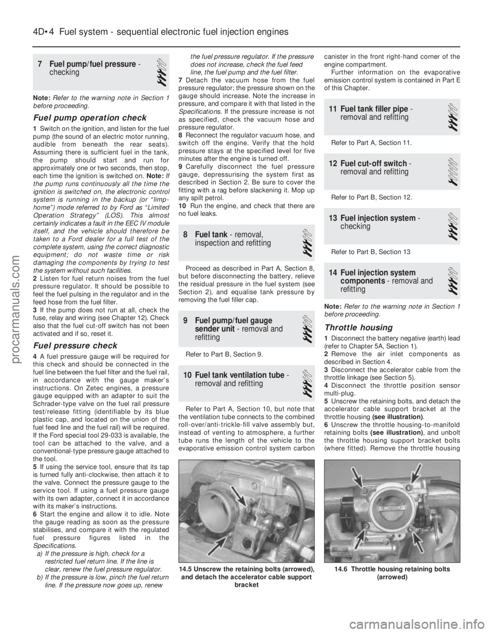
5 Unscrew the retaining bolts, and detach the
accelerator cable support bracket at the
throttle housing (see illustration) .
6 Unscrew the throttle housing-to-manifold
retaining bolts (see illustration) , and unbolt
the throttle housing support bracket bolts
(where fitted). Remove the throttle housing
4D•4 Fuel system - sequential electronic fuel injection engines
14.6 Throttle housing retaining bolts
(arrowed)14.5 Unscrew the retaining bolts (arrowed),and detach the accelerator cable support
bracket
1595Ford Fiesta Remakeprocarmanuals.com
http://vnx.su