mirror FORD FIESTA 1989 Service Repair Manual
[x] Cancel search | Manufacturer: FORD, Model Year: 1989, Model line: FIESTA, Model: FORD FIESTA 1989Pages: 296, PDF Size: 10.65 MB
Page 18 of 296
point at the engine to the end of the tailpipe.
Ideally, this should be done on a hoist, where
unrestricted access is available; if a hoist is
not available, raise and support the vehicle on
axle stands.
2Check the pipes and connections for
evidence of leaks, severe corrosion, or
damage. Make sure that all brackets and
rubber mountings are in good condition, and
tight; if any of the mountings are to be
renewed, ensure that the replacements are of
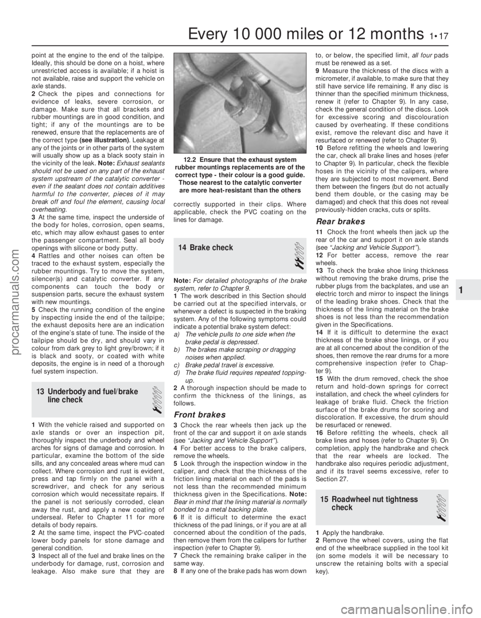
the correct type (see illustration) . Leakage at
any of the joints or in other parts of the system
will usually show up as a black sooty stain in
the vicinity of the leak. Note: Exhaust sealants
should not be used on any part of the exhaust
system upstream of the catalytic converter -
even if the sealant does not contain additives
harmful to the converter, pieces of it may
break off and foul the element, causing local
overheating.
3 At the same time, inspect the underside of
the body for holes, corrosion, open seams,
etc, which may allow exhaust gases to enter
the passenger compartment. Seal all body
openings with silicone or body putty.
4 Rattles and other noises can often be
traced to the exhaust system, especially the
rubber mountings. Try to move the system,
silencer(s) and catalytic converter. If any
components can touch the body or
suspension parts, secure the exhaust system
with new mountings.
5 Check the running condition of the engine
by inspecting inside the end of the tailpipe;
the exhaust deposits here are an indication
of the engine’s state of tune. The inside of the
tailpipe should be dry, and should vary in
colour from dark grey to light grey/brown; if it
is black and sooty, or coated with white
deposits, the engine is in need of a thorough
fuel system inspection.
13 Underbody and fuel/brake line check
1
1With the vehicle raised and supported on
axle stands or over an inspection pit,
thoroughly inspect the underbody and wheel
arches for signs of damage and corrosion. In
particular, examine the bottom of the side
sills, and any concealed areas where mud can
collect. Where corrosion and rust is evident,
press and tap firmly on the panel with a
screwdriver, and check for any serious
corrosion which would necessitate repairs. If
the panel is not seriously corroded, clean
away the rust, and apply a new coating of
underseal. Refer to Chapter 11 for more
details of body repairs.
2 At the same time, inspect the PVC-coated
lower body panels for stone damage and
general condition.
3 Inspect all of the fuel and brake lines on the
underbody for damage, rust, corrosion and
leakage. Also make sure that they are correctly supported in their clips. Where
applicable, check the PVC coating on the
lines for damage.
14 Brake check
2
Note:
For detailed photographs of the brake
system, refer to Chapter 9.
1 The work described in this Section should
be carried out at the specified intervals, or
whenever a defect is suspected in the braking
system. Any of the following symptoms could
indicate a potential brake system defect:
a) The vehicle pulls to one side when the brake pedal is depressed.
b) The brakes make scraping or dragging
noises when applied.
c) Brake pedal travel is excessive.
d) The brake fluid requires repeated topping-
up.
2 A thorough inspection should be made to
confirm the thickness of the linings, as
follows.
Front brakes
3 Chock the rear wheels then jack up the
front of the car and support it on axle stands
(see “Jacking and Vehicle Support” ).
4 For better access to the brake calipers,
remove the wheels.
5 Look through the inspection window in the
caliper, and check that the thickness of the
friction lining material on each of the pads is
not less than the recommended minimum
thickness given in the Specifications. Note:
Bear in mind that the lining material is normally
bonded to a metal backing plate.
6 If it is difficult to determine the exact
thickness of the pad linings, or if you are at all
concerned about the condition of the pads,
then remove them from the calipers for further
inspection (refer to Chapter 9).
7 Check the remaining brake caliper in the
same way.
8 If any one of the brake pads has worn down to, or below, the specified limit,
all fourpads
must be renewed as a set.
9 Measure the thickness of the discs with a
micrometer, if available, to make sure that they
still have service life remaining. If any disc is
thinner than the specified minimum thickness,
renew it (refer to Chapter 9). In any case,
check the general condition of the discs. Look
for excessive scoring and discolouration
caused by overheating. If these conditions
exist, remove the relevant disc and have it
resurfaced or renewed (refer to Chapter 9).
10 Before refitting the wheels and lowering
the car, check all brake lines and hoses (refer
to Chapter 9). In particular, check the flexible
hoses in the vicinity of the calipers, where
they are subjected to most movement. Bend
them between the fingers (but do not actually
bend them double, or the casing may be
damaged) and check that this does not reveal
previously-hidden cracks, cuts or splits.
Rear brakes
11 Chock the front wheels then jack up the
rear of the car and support it on axle stands
(see “Jacking and Vehicle Support” ).
12 For better access, remove the rear
wheels.
13 To check the brake shoe lining thickness
without removing the brake drums, prise the
rubber plugs from the backplates, and use an
electric torch and mirror to inspect the linings
of the leading brake shoes. Check that the
thickness of the lining material on the brake
shoes is not less than the recommendation
given in the Specifications.
14 If it is difficult to determine the exact
thickness of the brake shoe linings, or if you
are at all concerned about the condition of the
shoes, then remove the rear drums for a more
comprehensive inspection (refer to Chap-
ter 9).
15 With the drum removed, check the shoe
return and hold-down springs for correct
installation, and check the wheel cylinders for
leakage of brake fluid. Check the friction
surface of the brake drums for scoring and
discoloration. If excessive, the drum should
be resurfaced or renewed.
16 Before refitting the wheels, check all
brake lines and hoses (refer to Chapter 9). On
completion, apply the handbrake and check
that the rear wheels are locked. The
handbrake also requires periodic adjustment,
and if its travel seems excessive, refer to
Section 27.
15 Roadwheel nut tightness check
1
1Apply the handbrake.
2 Remove the wheel covers, using the flat
end of the wheelbrace supplied in the tool kit
(on some models it will be necessary to
unscrew the retaining bolts with a special
key).
Every 10 000 miles or 12 months1•17
12.2 Ensure that the exhaust system
rubber mountings replacements are of the correct type - their colour is a good guide. Those nearest to the catalytic converterare more heat-resistant than the others
1
1595Ford Fiesta Remakeprocarmanuals.com
http://vnx.su
Page 19 of 296
3Check that the roadwheel nuts are tightened
to the specified torque wrench setting.
4 Refit the wheel covers.
16 Door, tailgate and bonnet
check and lubrication
1
1Check that the doors and tailgate/boot lid
close securely. Check that the bonnet safety
catch operates correctly. Check the operation
of the door check straps.
2 Lubricate the hinges, door check straps,
the striker plates and the bonnet catch
sparingly with a little oil or grease.
17 Seat belt check
1
1 Check the seat belts for satisfactory
operation and condition. Inspect the webbing
for fraying and cuts. Check that they retract
smoothly and without binding into their reels.
2 Check that the seat belt mounting bolts are
tight, and if necessary tighten them to the
specified torque wrench settings as given in
Chapter 11.
18 Bodywork, paint and exterior trim check
1
1The best time to carry out this check is after
the car has been washed so that any surface
blemish or scratch will be clearly evident and
not hidden by a film of dirt.
2 Starting at one front corner check the
paintwork all around the car, looking for minor
scratches or more serious dents. Check all
the trim and make sure that it is securely
attached over its entire length.
3 Check the security of all door locks, door
mirrors, badges, bumpers, front grille and
wheel trim. Anything found loose, or in need of
further attention should be done with reference
to the relevant Chapters of this manual.
4 Rectify any problems noticed with the
paintwork or body panels as described in
Chapter 11.
19 Road test
1
Check the operation and
performance of the braking
system
1 Make sure that the vehicle does not pull to
one side when braking, and that the wheels
do not lock prematurely when braking hard.
2 Check that there is no vibration through the
steering when braking. 3
Check that the handbrake operates
correctly, without excessive movement of the
lever, and that it holds the vehicle stationary
on a slope.
4 Test the operation of the brake servo unit
as follows. With the engine switched off,
depress the footbrake four or five times to
exhaust the vacuum, then hold the pedal
depressed. Start the engine, and there should
be a noticeable “give” in the brake pedal as
vacuum builds up. Allow the engine to run for
at least two minutes, and then switch it off. If
the brake pedal is depressed again, it should
be possible to detect a hiss from the servo as
the pedal is depressed. After about four or five
applications, no further hissing should be
heard, and the pedal should feel considerably
firmer.
Steering and suspension
5 Check for any abnormalities in the steering,
suspension, handling or road “feel”.
6 Drive the vehicle, and check that there are
no unusual vibrations or noises.
7 Check that the steering feels positive, with
no excessive sloppiness or roughness, and
check for any suspension noises when
cornering and driving over bumps.
Drivetrain
8 Check the performance of the engine,
transmission and driveshafts.
9 Check that the engine starts correctly, both
when cold and when hot.
10 Listen for any unusual noises from the
engine and transmission.
11 Make sure that the engine runs smoothly
when idling, and that there is no hesitation
when accelerating.
12 On manual transmission models, check
that all gears can be engaged smoothly
without noise, and that the gear lever action is
not abnormally vague or “notchy”.
13 On automatic transmission models, make
sure that the drive seems smooth without
jerks or engine speed “flare-ups”. Check that
all the gear positions can be selected with the
vehicle at rest. If any problems are found, they
should be referred to a Ford dealer.
14 Listen for a metallic clicking sound from
the front of the vehicle, as the vehicle is driven
slowly in a circle with the steering on full-lock.
Carry out this check in both directions. If a
clicking noise is heard, this indicates wear in a
driveshaft joint, in which case renew the joint
if necessary.
Clutch
15 Check that the clutch pedal moves
smoothly and easily through its full travel, and
that the clutch itself functions correctly, with
no trace of slip or drag. If the movement is
uneven or stiff in places, check that the cable
is routed correctly, with no sharp turns.
16 Inspect both ends of the clutch inner
cable, both at the transmission end and inside
the car, for signs of wear and fraying.
Instruments and electrical
equipment
17 Check the operation of all instruments
and electrical equipment.
18 Make sure that all instruments read
correctly, and switch on all electrical equipment
in turn, to check that it functions properly.
20 Automatic transmission fluid level check
1
1The level of the automatic transmission fluid
should be carefully maintained. Low fluid level
can lead to slipping or loss of drive, while
overfilling can cause foaming, loss of fluid and
transmission damage.
2 The transmission fluid level should only be
checked when the transmission is hot (at its
normal operating temperature). If the vehicle
has just been driven over 10 miles (15 miles in
a cold climate), and the fluid temperature is 60
to 70ºC, the transmission is hot.
Caution: If the vehicle has just been driven
for a long time at high speed or in city
traffic in hot weather, or if it has been
pulling a trailer, an accurate fluid level
reading cannot be obtained. In these
circumstances, allow the fluid to cool
down for about 30 minutes.
3 Park the vehicle on level ground, apply the
handbrake, and start the engine. While the
engine is idling, depress the brake pedal and
move the selector lever through all the gear
positions three times, beginning and ending in
“P”.
4 Allow the engine to idle for one minute, then
(with the engine still idling) remove the
dipstick from its tube. Note the condition and
colour of the fluid on the dipstick.
5 Wipe the fluid from the dipstick with a clean
rag, and re-insert it into the filler tube until the
cap seats.
6 Pull the dipstick out again, and note the
fluid level. The level should be between
the “MIN” and “MAX” marks. If the level is
on the “MIN” mark, stop the engine, and add
the specified automatic transmission fluid
through the dipstick tube, using a clean funnel
if necessary. It is important not to introduce
dirt into the transmission when topping-up.
7 Add the fluid a little at a time, and keep
checking the level as previously described
until it is correct. The difference between the
“MIN” and “MAX” marks on the dipstick is
approximately 0.4 litres.
8 The need for regular topping-up of the
transmission fluid indicates a leak, which
should be found and rectified without delay.
9 The condition of the fluid should also be
checked along with the level. If the fluid on the
dipstick is black or a dark reddish-brown
colour, or if it has a burned smell, the fluid
should be changed. If you are in doubt about
the condition of the fluid, purchase some new
fluid, and compare the two for colour and smell.
1•18Every 10 000 miles or 12 months
1595Ford Fiesta Remakeprocarmanuals.com
http://vnx.su
Page 212 of 296
11
1595Ford Fiesta Remake
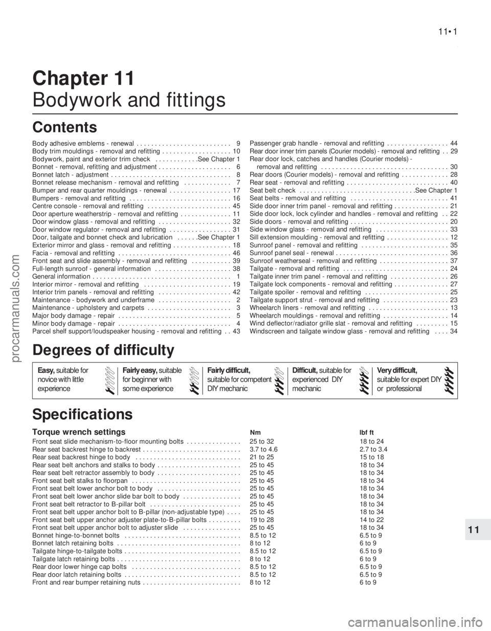
Torque wrench settingsNmlbf ft
Front seat slide mechanism-to-floor mounting bolts . . . . . . . . . . . . . . . 25 to 32 18 to 24
Rear seat backrest hinge to backrest . . . . . . . . . . . . . . . . . . . . . . . . . . . 3.7 to 4.6 2.7 to 3.4
Rear seat backrest hinge to body . . . . . . . . . . . . . . . . . . . . . . . . . . . . . 21 to 25 15 to 18
Rear seat belt anchors and stalks to body . . . . . . . . . . . . . . . . . . . . . . . 25 to 45 18 to 34
Rear seat belt retractor assembly to body . . . . . . . . . . . . . . . . . . . . . . . 25 to 45 18 to 34
Front seat belt stalks to floorpan . . . . . . . . . . . . . . . . . . . . . . . . . . . . . . 25 to 45 18 to 34
Front seat belt lower anchor bolt to body . . . . . . . . . . . . . . . . . . . . . . . 25 to 45 18 to 34
Front seat belt lower anchor slide bar bolt to body . . . . . . . . . . . . . . . . 25 to 45 18 to 34
Front seat belt retractor to B-pillar bolt . . . . . . . . . . . . . . . . . . . . . . . . . 25 to 45 18 to 34
Front seat belt upper anchor bolt to B-pillar (non-adjustable type) . . . . 25 to 45 18 to 34
Front seat belt upper anchor adjuster plate-to-B-pillar bolts . . . . . . . . . 19 to 28 14 to 22
Front seat belt upper anchor bolt to adjuster slide . . . . . . . . . . . . . . . . 25 to 45 18 to 34
Bonnet hinge-to-bonnet bolts . . . . . . . . . . . . . . . . . . . . . . . . . . . . . . . . 8.5 to 12 6.5 to 9
Bonnet latch retaining bolts . . . . . . . . . . . . . . . . . . . . . . . . . . . . . . . . . . 8 to 12 6 to 9
Tailgate hinge-to-tailgate bolts . . . . . . . . . . . . . . . . . . . . . . . . . . . . . . . . 8.5 to 12 6.5 to 9
Tailgate latch retaining bolts . . . . . . . . . . . . . . . . . . . . . . . . . . . . . . . . . . 8 to 12 6 to 9
Rear door lower hinge cap bolts . . . . . . . . . . . . . . . . . . . . . . . . . . . . . . 8.5 to 12 6.5 to 9
Rear door latch retaining bolts . . . . . . . . . . . . . . . . . . . . . . . . . . . . . . . . 8.5 to 12 6.5 to 9
Front and rear bumper retaining nuts . . . . . . . . . . . . . . . . . . . . . . . . . . . 8 to 12 6 to 9
Chapter 11
Bodywork and fittings
Body adhesive emblems - renewal . . . . . . . . . . . . . . . . . . . . . . . . . . 9
Body trim mouldings - removal and refitting . . . . . . . . . . . . . . . . . . . 10
Bodywork, paint and exterior trim check . . . . . . . . . . . .See Chapter 1
Bonnet - removal, refitting and adjustment . . . . . . . . . . . . . . . . . . . . 6
Bonnet latch - adjustment . . . . . . . . . . . . . . . . . . . . . . . . . . . . . . . . . 8
Bonnet release mechanism - removal and refitting . . . . . . . . . . . . . 7
Bumper and rear quarter mouldings - renewal . . . . . . . . . . . . . . . . . 17
Bumpers - removal and refitting . . . . . . . . . . . . . . . . . . . . . . . . . . . . 16
Centre console - removal and refitting . . . . . . . . . . . . . . . . . . . . . . . 45
Door aperture weatherstrip - removal and refitting . . . . . . . . . . . . . . 11
Door window glass - removal and refitting . . . . . . . . . . . . . . . . . . . . 32
Door window regulator - removal and refitting . . . . . . . . . . . . . . . . . 31
Door, tailgate and bonnet check and lubrication . . . . . .See Chapter 1
Exterior mirror and glass - removal and refitting . . . . . . . . . . . . . . . . 18
Facia - removal and refitting . . . . . . . . . . . . . . . . . . . . . . . . . . . . . . . 46
Front seat and slide assembly - removal and refitting . . . . . . . . . . . 39
Full-length sunroof - general information . . . . . . . . . . . . . . . . . . . . . 38
General information . . . . . . . . . . . . . . . . . . . . . . . . . . . . . . . . . . . .\
. . 1
Interior mirror - removal and refitting . . . . . . . . . . . . . . . . . . . . . . . . 19
Interior trim panels - removal and refitting . . . . . . . . . . . . . . . . . . . . 42
Maintenance - bodywork and underframe . . . . . . . . . . . . . . . . . . . . 2
Maintenance - upholstery and carpets . . . . . . . . . . . . . . . . . . . . . . . 3
Major body damage - repair . . . . . . . . . . . . . . . . . . . . . . . . . . . . . . . 5
Minor body damage - repair . . . . . . . . . . . . . . . . . . . . . . . . . . . . . . . 4
Parcel shelf support/loudspeaker housing - removal and refitting . . 43 Passenger grab handle - removal and refitting . . . . . . . . . . . . . . . . . 44
Rear door inner trim panels (Courier models) - removal and refitting . . 29
Rear door lock, catches and handles (Courier models) -
removal and refitting . . . . . . . . . . . . . . . . . . . . . . . . . . . . . . . . . . . 30
Rear doors (Courier models) - removal and refitting . . . . . . . . . . . . . 28
Rear seat - removal and refitting . . . . . . . . . . . . . . . . . . . . . . . . . . . . 40
Seat belt check . . . . . . . . . . . . . . . . . . . . . . . . . . . . . . . .See Chap\
ter 1
Seat belts - removal and refitting . . . . . . . . . . . . . . . . . . . . . . . . . . . 41
Side door inner trim panel - removal and refitting . . . . . . . . . . .\
. . . . 21
Side door lock, lock cylinder and handles - removal and refitting . . 22
Side doors - removal and refitting . . . . . . . . . . . . . . . . . . . . . . . . . . . 20
Side window glass - removal and refitting . . . . . . . . . . . . . . . . . . . . 33
Sill extension moulding - removal and refitting . . . . . . . . . . . . . . . . . 12
Sunroof panel - removal and refitting . . . . . . . . . . . . . . . . . . . . . . . . 35
Sunroof panel seal - renewal . . . . . . . . . . . . . . . . . . . . . . . . . . . . . . . 36
Sunroof weatherseal - removal and refitting . . . . . . . . . . . . . . . . . . . 37
Tailgate - removal and refitting . . . . . . . . . . . . . . . . . . . . . . . . . . . . . 24
Tailgate inner trim panel - removal and refitting . . . . . . . . . . . . . . . . 26
Tailgate lock components - removal and refitting . . . . . . . . . . . . . . . 27
Tailgate spoiler - removal and refitting . . . . . . . . . . . . . . . . . . . . . . . 25
Tailgate support strut - removal and refitting . . . . . . . . . . . . . . . . . . 23
Wheelarch liners - removal and refitting . . . . . . . . . . . . . . . . . . . . . . 13
Wheelarch mouldings - removal and refitting . . . . . . . . . . . . . . . . . . 14
Wind deflector/radiator grille slat - removal and refitting . . . . . . . . . 15
Windscreen and tailgate window glass - removal and refitting . . . . 34
11•1
Specifications Contents
Easy, suitable for
novice with little
experience Fairly easy,
suitable
for beginner with
some experience Fairly difficult,
suitable for competent
DIY mechanic
Difficult,
suitable for
experienced DIY
mechanic Very difficult,
suitable for expert DIY
or professional
Degrees of difficulty
54321
procarmanuals.com
http://vnx.su
Page 217 of 296
Door belt weatherseal moulding
Removal
12Remove the exterior mirror, as described
in Section 18 then, using a screwdriver,
carefully prise up the moulding and remove it
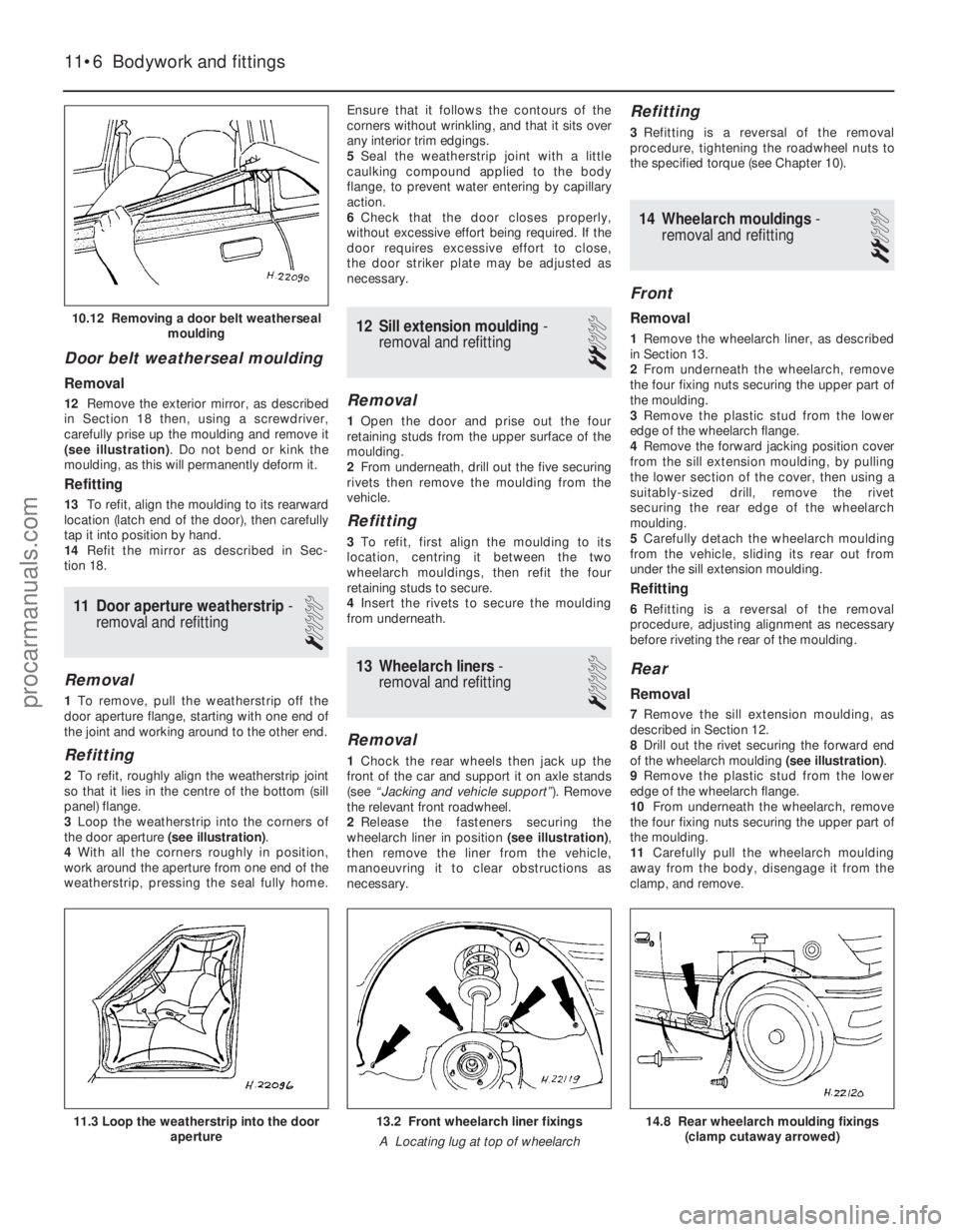
(see illustration) . Do not bend or kink the
moulding, as this will permanently deform it.
Refitting
13 To refit, align the moulding to its rearward
location (latch end of the door), then carefully
tap it into position by hand.
14 Refit the mirror as described in Sec-
tion 18.
11 Door aperture weatherstrip -
removal and refitting
1
Removal
1 To remove, pull the weatherstrip off the
door aperture flange, starting with one end of
the joint and working around to the other end.
Refitting
2 To refit, roughly align the weatherstrip joint
so that it lies in the centre of the bottom (sill
panel) flange.
3 Loop the weatherstrip into the corners of
the door aperture (see illustration).
4 With all the corners roughly in position,
work around the aperture from one end of the
weatherstrip, pressing the seal fully home. Ensure that it follows the contours of the
corners without wrinkling, and that it sits over
any interior trim edgings.
5
Seal the weatherstrip joint with a little
caulking compound applied to the body
flange, to prevent water entering by capillary
action.
6 Check that the door closes properly,
without excessive effort being required. If the
door requires excessive effort to close,
the door striker plate may be adjusted as
necessary.
12 Sill extension moulding -
removal and refitting
2
Removal
1 Open the door and prise out the four
retaining studs from the upper surface of the
moulding.
2 From underneath, drill out the five securing
rivets then remove the moulding from the
vehicle.
Refitting
3 To refit, first align the moulding to its
location, centring it between the two
wheelarch mouldings, then refit the four
retaining studs to secure.
4 Insert the rivets to secure the moulding
from underneath.
13 Wheelarch liners -
removal and refitting
1
Removal
1 Chock the rear wheels then jack up the
front of the car and support it on axle stands
(see “Jacking and vehicle support” ). Remove
the relevant front roadwheel.
2 Release the fasteners securing the
wheelarch liner in position (see illustration),
then remove the liner from the vehicle,
manoeuvring it to clear obstructions as
necessary.
Refitting
3 Refitting is a reversal of the removal
procedure, tightening the roadwheel nuts to
the specified torque (see Chapter 10).
14 Wheelarch mouldings -
removal and refitting
2
Front
Removal
1 Remove the wheelarch liner, as described
in Section 13.
2 From underneath the wheelarch, remove
the four fixing nuts securing the upper part of
the moulding.
3 Remove the plastic stud from the lower
edge of the wheelarch flange.
4 Remove the forward jacking position cover
from the sill extension moulding, by pulling
the lower section of the cover, then using a
suitably-sized drill, remove the rivet
securing the rear edge of the wheelarch
moulding.
5 Carefully detach the wheelarch moulding
from the vehicle, sliding its rear out from
under the sill extension moulding.
Refitting
6 Refitting is a reversal of the removal
procedure, adjusting alignment as necessary
before riveting the rear of the moulding.
Rear
Removal
7 Remove the sill extension moulding, as
described in Section 12.
8 Drill out the rivet securing the forward end
of the wheelarch moulding (see illustration).
9 Remove the plastic stud from the lower
edge of the wheelarch flange.
10 From underneath the wheelarch, remove
the four fixing nuts securing the upper part of
the moulding.
11 Carefully pull the wheelarch moulding
away from the body, disengage it from the
clamp, and remove.
11•6 Bodywork and fittings
14.8 Rear wheelarch moulding fixings (clamp cutaway arrowed)13.2 Front wheelarch liner fixings
A Locating lug at top of wheelarch11.3 Loop the weatherstrip into the door aperture
10.12 Removing a door belt weathersealmoulding
1595Ford Fiesta Remakeprocarmanuals.com
http://vnx.su
Page 219 of 296

arch, then remove the two bolts securing each
bumper mounting bracket to the rear
underside of the vehicle (see illustration).
Withdraw the bumper.
19 The mounting brackets can be unbolted, if
required, from the bumper. The end
mouldings can be unclipped for renewal
separately (see illustrations) .
Refitting
20Refitting is the reverse of the removal
procedure.
17 Bumper and rear quarter
mouldings - renewal
2
Bumper mouldings
1With the bumper removed as described in
Section 16, place it on a clean flat surface,
then remove the clips from the moulding
ends.
2 Prise up and remove the old moulding from
its bumper recess.
3 Remove all trace of old adhesive from the
bumper recess, using methylated spirit, taking
all normal safety precautions. Allow the recess
to dry.
4 If fitting a new moulding to a service
replacement bumper, slots must be cut into
the bumper to accommodate the moulding
end fixings (see illustration) .
5 Apply adhesive primer (available from Ford
dealers) to the recess, and allow it to dry.
6 Gently heat the moulding until it is warm to
the touch, then insert the first moulding end
clip into the bumper and press the moulding
to its recess, secured with its moulding end,
peeling the protective backing paper off as it
is applied.
7 Apply the moulding smoothly and carefully
across the bumper, rolling into its recess using a plastic roller or similar tool, then, when
the other end is reached, secure with the
other moulding end and clip.
Rear quarter mouldings (Courier
models)
8
Remove the rear bumper as described in
Section 16.
9 Each moulding is secured by two screws at
its forward edge, in the wheel arch, and by a
single screw at the rear (see illustrations).
Remove the screws and withdraw the
moulding, unclipping it at its front end.
10 Refitting is the reverse of the removal
procedure.
18 Exterior mirror and glass -
removal and refitting
1
Mirror glass
Removal
1 Insert a thin flat-headed screwdriver behind
the mirror glass, at the upper outermost
corner, then carefully lever the glass assembly
forward to disconnect the outer pivot (see
illustration) .
11•8Bodywork and fittings
18.1 Removing the door mirror glass from
the mirror housing17.9b . . . and at rear of vehicle17.9a Courier rear quarter mouldingmounting screws (arrowed) in wheel
arch . . .
17.4 Bumper moulding slot required on
service replacement bumpers (dimensions given in mm)
16.19b . . . Courier rear bumper endmoulding unclipped16.19a Courier rear bumper removed,
showing mounting bracket retaining nut and end moulding clips . . .16.18 Courier rear bumper mounting
screws (arrowed) at wheel arch - note also bumper mounting bracket bolts (arrowed) visible under rear of vehicle
1595Ford Fiesta Remakeprocarmanuals.com
http://vnx.su
Page 220 of 296

2Disengage the inner pivot then, using a
screwdriver, disconnect the operating link to
allow the glass assembly to be withdrawn
(see illustration) .
Refitting
3To refit, first reconnect the operating link
and engage the inner pivot.
4 Align the outer pivot in the mirror housing,
then push the glass assembly carefully into
position so that the outer pivot engages
fully.
Mirror assembly
Removal
5 Remove the door inner trim panel as
described in Section 21.
6 Remove the door mirror operating knob by
lifting its retaining clip, using a small
screwdriver, then pulling it from its shaft (see
illustration) .
7 Remove the mirror trim retaining screw,
then ease the mirror trim out from its forward
lug location and slide it out towards the rear of
the vehicle, to clear its rearward fixings (see
illustration) .
8 Remove the three mirror retaining screws,
and manoeuvre the mirror from the door (see
illustration) .
Refitting
9Refitting is the reverse sequence to
removal.
19 Interior mirror -
removal and refitting
1
Removal
1 Using a length of strong thin cord or fishing
line, break the adhesive bond between the
mirror base and the windscreen, then remove
the mirror from the vehicle.
2 During installation, it is important to note
that the mirror base, windscreen black patch
and the adhesive patch should not be
touched, other than for cleaning, or the
adhesive bond may be adversely affected.
3 Remove all traces of old adhesive from the
mirror base, using a lint-free cloth and
methylated spirit, taking all normal safety
precautions. Allow the mirror base to dry.
4 Clean the windscreen black patch in a
similar manner.
Refitting
5 Note that, before installing the mirror, the vehicle should have been in an ambient
temperature of approximately 20ºC for at least
an hour.
6
With the contact surfaces scrupulously
clean, remove the protective tape from one
side of the adhesive patch and press firmly
into contact with the mirror base.
7 Note that when fitting a mirror to a new
windscreen, the protective tape must be
removed from the windscreen black patch.
8 Warm the mirror base and adhesive patch
for about thirty seconds, to a temperature of
50 to 70ºC.
9 Remove the protective tape from the other
side of the adhesive patch on the mirror base,
then align the mirror base and windscreen
black patch accurately, and firmly press the
mirror base into position. Hold the mirror base
firmly in position for at least two minutes.
10 Wait at least thirty minutes before
adjusting the mirror.
20 Side doors -
removal and refitting
2
Removal
1 Open the door and detach the door
aperture weatherseal from around the hinge
area.
2 Remove the screw securing the door check
arm to the body.
3 Squeeze the ears together on the electrical
multi-plug and withdraw it from its body
location on the A-pillar, as applicable.
Disconnect the multi-plug.
4 Using a screwdriver, remove the door hinge
pin retaining clips from the top of both hinges,
by levering them off.
5 Ford dealers use a special tool for removing
door hinge pins. If this is not available, it is
possible to fabricate an alternative. Engage
Bodywork and fittings 11•9
18.6 Lift the retaining clip, then pull the door mirror operating knob from its shaft18.2 Mirror glass connections within mirror housing
A Inner pivot B Operating link C Outer pivot
18.8 Removing the three mirror retaining screws (arrowed)18.7 Removing the mirror trim retaining screw
11
1595Ford Fiesta Remakeprocarmanuals.com
http://vnx.su
Page 221 of 296

the special tool (see illustration) , then strike
the main body of the tool with a soft-faced
hammer to extract the lower hinge pin from its
location.
6 With the help of an assistant to support the
door, remove the upper hinge pin from its
location, in a similar manner to that used for
the lower hinge pin, and then remove the door
assembly.
Refitting
7 To refit, align the door hinge sections to the
hinge sections on the body, and insert both
hinge pins as far as possible, by hand.
Ensuring that the hinge pins have entered all
three sections of hinge, tap them gently
through, with a soft-faced hammer, until their
retaining clips can be fitted. New retaining
clips should be used. 8
Reconnect the multi-plug and insert it to its
body location on the A- pillar, ensuring that it
seats correctly.
9 Refit the door check arm to its body
location. Press the door aperture weatherseal
back into position on its flange.
10 There should be no need to adjust the
door striker, or check door alignment.
21 Side door inner trim panel -
removal and refitting
1
Removal
1 Using a screwdriver with a broad flat blade,
carefully prise up and remove the interior
weatherstrip from its location at the top of the
door trim panel. Be careful not to kink or bend
it as it is being removed. On front doors, pull the end of the weatherstrip out from under the
door mirror trim.
2
Detach the door interior release handle
bezel by removing its retaining screw (see
illustration) .
3 Using a small thin screwdriver, release the
window regulator handle (where fitted) by
releasing its spring clip from behind and pulling
it from the regulator shaft (see illustration).
Remove its bezel also. On models with electric
front window switches in the door trim panel,
disconnect the switch wiring multi-plugs as the
trim panel is withdrawn.
4 Detach the armrest/doorpull assembly from
the door. Some models are fitted with an
armrest/doorpull secured by three screws,
two of which are concealed behind a
removable panel. Certain lower specification
vehicles have the door pull secured with only
two screws. (see illustrations)
5 On front doors, remove the three screws
securing the door stowage pocket/speaker
grille moulding, then pull the moulding upper
edge away from the door, and disengage the
hook fixings on its base from their locations
(see illustration) .
6 Using a trim clip tool, release the retaining
clips around the base and the sides of the
panel, then raise it to free it from the door. If a
trim clip tool is unavailable, two thin flat-
bladed screwdrivers carefully inserted
between the trim panel and the door may
suffice. Place the screwdrivers on each side
of the clips and then apply gentle leverage.
11•10 Bodywork and fittings
21.4b Undoing armrest/doorpull retaining screws21.4a Detaching armrest/doorpullremovable panel
21.3 Window regulator handle. Inset shows removal
A Spring clip
B Rotate the tag to remove the knob
21.2 Removing the door interior release handle bezel (armrest/doorpull shown removed)
1595Ford Fiesta Remake
20.5 Door hinge pin removal using Ford special tools
A Hinge pin B Removal tool C Soft-faced hammer
procarmanuals.com
http://vnx.su
Page 222 of 296

Refitting
7To refit, first align the trim panel to the door,
secure its upper edge into its hook fastenings,
then press into position to engage the trim
clips. Where electric window switches are
fitted, reconnect the switch wiring multi-plugs
before fitting the panel.
8 If necessary, refit the clip to the window
regulator handle, then refit the handle to the
regulator shaft by pushing it on. The clip
should engage positively, in the annular
groove on the shaft.
9 Refit the door stowage pocket/speaker
grille moulding, armrest/doorpull and door
interior release handle bezel, as applicable, by
reversing the method of removal.
10 Refit the interior weatherstrip to its
location, tapping it down into position, being
careful not to bend or kink it. On front doors, it
will be necessary to slide its forward edge
under the door mirror trim before tapping into
position.
22 Side door lock, lock cylinder
and handles - removal and
refitting
2
Exterior handle
Removal
1 Remove the door inner trim panel, as
described in Section 21.
2 Locally detach the PVC sheet from the door
to allow access into the door cavity. Do not
tear the sheet; cut closely around the clips, as
required.
3 Disconnect the handle operating rod from
the latch assembly, by twisting the clip and
withdrawing the rod, as applicable.
4 Remove the two screws securing the
handle then, from the outside, withdraw
the handle and rod, guiding the rod out
through the door skin as necessary (see
illustrations) . The handle and rod may be
disconnected as required.
Refitting
5 Refitting is a reversal of the removal
procedure. On completion, re-secure the PVC
sheet then refit the inner trim panel as
described in Section 21.
Door lock barrel
Removal
6 Remove the door inner trim panel, as
described in Section 21.
7 Locally detach the PVC sheet from the door
to allow access into the door cavity. Do not
tear the sheet; cut closely around the clips, as
required.
8 Drill out the rivets securing the door glass
guide above the lock barrel, and remove it.
9 Disconnect the lock barrel operating rod
from the latch assembly, by twisting the clip
and withdrawing the rod.
10 Release the lock barrel retaining clip by
withdrawing it upwards, then from the
outside, withdraw the lock barrel and rod,
guiding the rod out through the door skin. The
lock barrel and rod may be disconnected as
required.
Refitting
11 Refitting is a reversal of the removal
procedure. Ensure that the lock barrel gasket
is located correctly between the lock barrel
outer surround and the door skin, and that the door glass guide is riveted securely. Check
that the window operates smoothly and
correctly, by temporarily refitting the regulator
handle or operating the electric window
motor.
12
On completion, re-secure the PVC sheet
then refit the inner trim panel as described in
Section 21.
Door latch and interior release
handle
Removal
13 Remove the door inner trim panel, as
described in Section 21.
14 Locally detach the PVC sheet from the
door to allow access into the door cavity. Do
not tear the sheet; cut closely around the
clips, as required.
15 On rear doors fitted with central locking,
undo the two screws securing the rod guard
and remove it (see illustration) .
16 Disconnect the operating rods from the
latch assembly as necessary. On rear doors
with central locking, disconnect and release
the motor loom multi-plug assembly, and
withdraw the motor side of the loom back into
the door cavity. Undo the three screws
securing the motor assembly, disengage its
operating rod and remove it from the vehicle
(see illustration) .
Bodywork and fittings 11•11
22.4b Removing the door exterior handle,
guiding its operating rod out through the door skin (front door)22.4a Door exterior handle and lock barrelsecuring arrangements (front door)
A Handle screw locations
B Lock barrel retaining clip21.5 Disengaging the hook fixings on the
base of the door stowage pocket/speaker grille moulding
22.16 Central locking motor retainingscrews (A), and loom multi-plug
assembly (B) on rear door22.15 Rod guard securing screws
(arrowed) on rear doors with central
locking only
11
1595Ford Fiesta Remakeprocarmanuals.com
http://vnx.su
Page 267 of 296

1595 Ford Fiesta Remake
REF
Dimensions and weights
Note:All figures are approximate, and may vary according to model. Refer to m\
anufacturer’s data for exact figures.
Dimensions
Overall length: 3/5 door hatchback models . . . . . . . . . . . . . . . . . . . . . . . . . . . . . . . . 3743 mm
XR2i, RS Turbo and RS 1800 models . . . . . . . . . . . . . . . . . . . . . . . . . 3801 mm
Courier models . . . . . . . . . . . . . . . . . . . . . . . . . . . . . . . . . . . .\
. . . . . . 4052 mm
Width (excluding mirrors): 3/5 door hatchback models . . . . . . . . . . . . . . . . . . . . . . . . . . . . . . . . 1606 mm
XR2i, RS Turbo and RS 1800 models . . . . . . . . . . . . . . . . . . . . . . . . . 1630 mm
Courier models . . . . . . . . . . . . . . . . . . . . . . . . . . . . . . . . . . . .\
. . . . . . 1650 mm
Overall height: 3/5 door hatchback models . . . . . . . . . . . . . . . . . . . . . . . . . . . . . . . . 1376 mm
XR2i, RS Turbo and RS 1800 models . . . . . . . . . . . . . . . . . . . . . . . . . 1365 mm
Courier models . . . . . . . . . . . . . . . . . . . . . . . . . . . . . . . . . . . .\
. . . . . . 1812 mm
Wheelbase: Courier models . . . . . . . . . . . . . . . . . . . . . . . . . . . . . . . . . . . .\
. . . . . . 2700 mm
All other models . . . . . . . . . . . . . . . . . . . . . . . . . . . . . . . . . . . .\
. . . . . 2446 mm
Front track: 3/5 door hatchback models . . . . . . . . . . . . . . . . . . . . . . . . . . . . . . . . 1392 mm
XR2i, RS Turbo and RS 1800 models . . . . . . . . . . . . . . . . . . . . . . . . . 1406 mm
Courier models . . . . . . . . . . . . . . . . . . . . . . . . . . . . . . . . . . . .\
. . . . . . 1392 mm
Rear track: 3/5 door hatchback models . . . . . . . . . . . . . . . . . . . . . . . . . . . . . . . . 1384 mm
XR2i, RS Turbo and RS 1800 models . . . . . . . . . . . . . . . . . . . . . . . . . 1376 mm
Courier models . . . . . . . . . . . . . . . . . . . . . . . . . . . . . . . . . . . .\
. . . . . . 1395 mm
Dimensions and weights . . . . . . . . . . . . . . . . REF•1
Vehicle identification . . . . . . . . . . . . . . . . . . . REF•3
General repair procedures . . . . . . . . . . . . . . REF•4
Jacking and vehicle support . . . . . . . . . . . . . REF•5
Buying spare parts . . . . . . . . . . . . . . . . . . . . REF•5
Radio/cassette unit anti-theft system . . . . . REF•5Conversion factors . . . . . . . . . . . . . . . . . . . .
REF•6
Tools and working facilities . . . . . . . . . . . . . . REF•7
MOT test checks . . . . . . . . . . . . . . . . . . . . . REF•10
Fault finding . . . . . . . . . . . . . . . . . . . . . . . . REF•14
Glossary of technical terms . . . . . . . . . . . . REF•22
Index . . . . . . . . . . . . . . . . . . . . . . . . . . . . . . REF•27
Reference REF•1
procarmanuals.com
http://vnx.su
Page 276 of 296
1595 Ford Fiesta Remake
REF•10MOT test checks
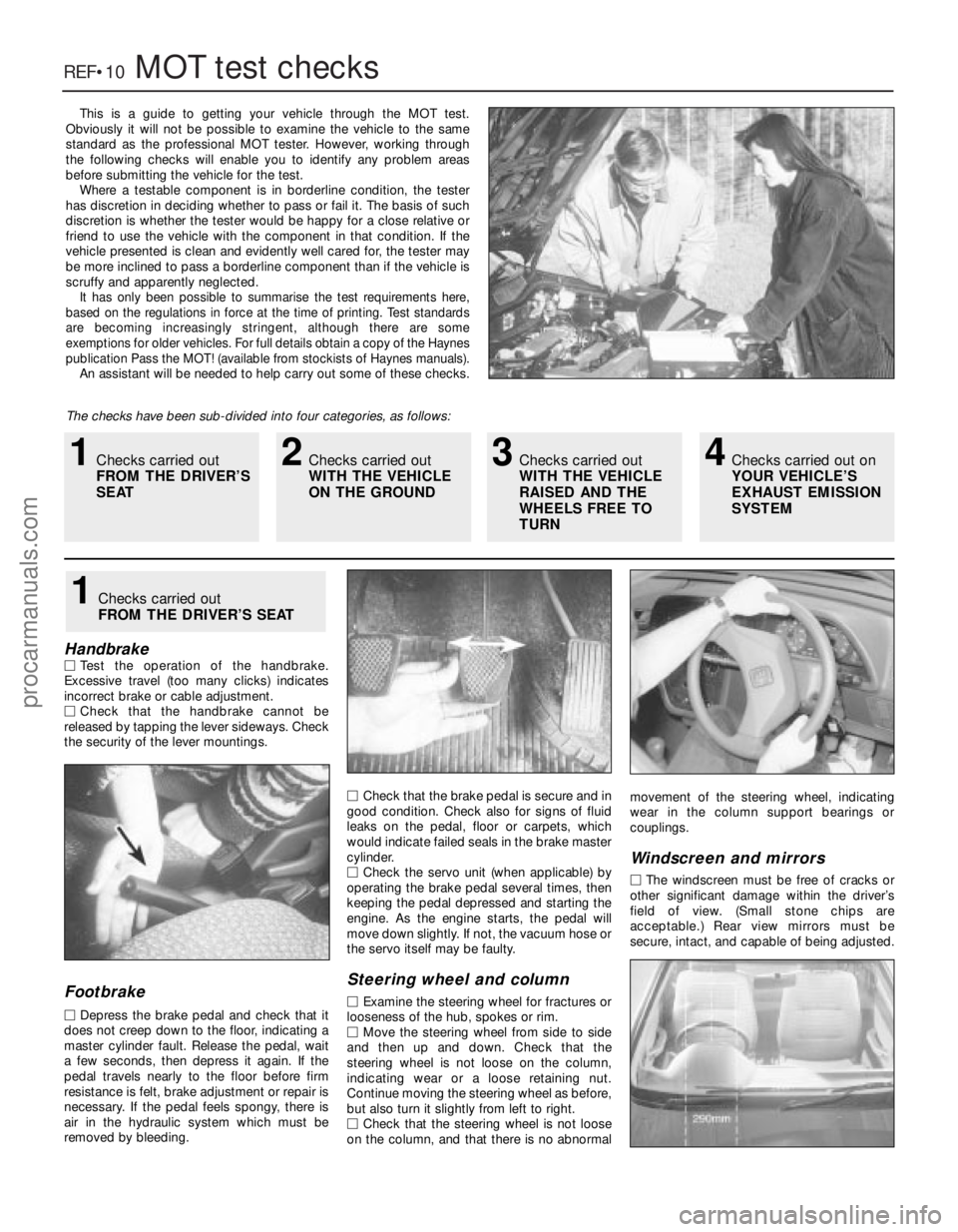
This is a guide to getting your vehicle through the MOT test.
Obviously it will not be possible to examine the vehicle to the same
standar d as the professional MOT tester. However, working through
the following checks will enable you to identify any problem areas
befor e submitting the vehicle for the test.
Wher e a testable component is in borderline condition, the tester
has discretion in deciding whether to pass or fail it. The basis of such
discr etion is whether the tester would be happy for a close relative or
friend to use the vehicle with the component in that condition. If the
vehicle presented is clean and evidently well cared for, the tester may
be more inclined to pass a borderline component than if the vehicle is
scruffy and apparently neglected.
It has only been possible to summarise the test requirements her e,
based on the regulations in force at the time of printing. Test standards ar e becoming increasingly stringent, although there are some
exemptions for older vehicles. For full details obtain a copy of the Hay\
nes
publication Pass the MOT! (available from stockists of Haynes manuals).
An assistant will be needed to help carry out some of these checks.
The checks have been sub-divided into four categories, as follows:
HandbrakeM Test the operation of the handbrake.
Excessive travel (too many clicks) indicates
incorr ect brake or cable adjustment.
M Check that the handbrake cannot be
r eleased by tapping the lever sideways. Check
the security of the lever mountings.
Footbrake
M Depr ess the brake pedal and check that it
does not creep down to the floor, indicating a master cylinder fault. Release the pedal, wait
a few seconds, then depress it again. If the
pedal travels nearly to the floor before firm
r esistance is felt, brake adjustment or repair is
necessary . If the pedal feels spongy, there is
air in the hydraulic system which must be
r emoved by bleeding. M
Check that the brake pedal is secure and in
good condition. Check also for signs of fluid
leaks on the pedal, floor or carpets, which
would indicate failed seals in the brake master
cylinder.
M Check the servo unit (when applicable) by
operating the brake pedal several times, then
keeping the pedal depressed and starting the
engine. As the engine starts, the pedal will
move down slightly. If not, the vacuum hose or
the servo itself may be faulty.
Steering wheel and column
M Examine the steering wheel for fractures or
looseness of the hub, spokes or rim.
M Move the steering wheel from side to side
and then up and down. Check that the
steering wheel is not loose on the column,
indicating wear or a loose retaining nut.
Continue moving the steering wheel as before,
but also turn it slightly from left to right.
M Check that the steering wheel is not loose
on the column, and that there is no abnormal movement of the steering wheel, indicating
wear in the column support bearings or
couplings.
W
indscreen and mirrors
M The windscreen must be free of cracks or
other significant damage within the driver’s
field of view. (Small stone chips are
acceptable.) Rear view mirrors must be
secur e, intact, and capable of being adjusted.
1Checks carried out
FROM THE DRIVER’S SEAT
1Checks carried out
FROM THE DRIVER’S
SEAT2Checks carried out
WITH THE VEHICLE
ON THE GROUND3Checks carried out
WITH THE VEHICLE
RAISED AND THE
WHEELS FREE TO
TURN4Checks carried out on
YOUR VEHICLE’S
EXHAUST EMISSION
SYSTEM
procarmanuals.com
http://vnx.su