service FORD FIESTA 1989 Service Repair Manual
[x] Cancel search | Manufacturer: FORD, Model Year: 1989, Model line: FIESTA, Model: FORD FIESTA 1989Pages: 296, PDF Size: 10.65 MB
Page 5 of 296
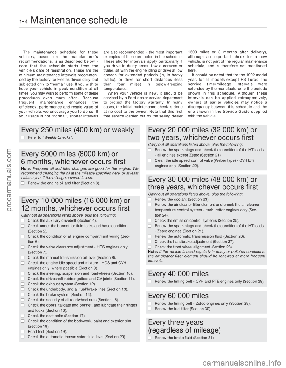
The maintenance schedule for these
vehicles, based on the manufacturer’s
recommendations, is as described below -
note that the schedule starts from the
vehicle’s date of registration. These are the
minimum maintenance intervals recommen-
ded by the factory for Fiestas driven daily, but
subjected only to “normal” use. If you wish to
keep your vehicle in peak condition at all
times, you may wish to perform some of these
procedures even more often. Because
frequent maintenance enhances the
efficiency, performance and resale value of
your vehicle, we encourage you to do so. If
your usage is not “normal”, shorter intervals are also recommended - the most important
examples of these are noted in the schedule.
These shorter intervals apply particularly if
you drive in dusty areas, tow a caravan or
trailer, sit with the engine idling or drive at low
speeds for extended periods (ie, in heavy
traffic), or drive for short distances (less
than four miles) in below-freezing
temperatures.
When your vehicle is new, it should be
serviced by a Ford dealer service department
to protect the factory warranty. In many
cases, the initial maintenance check is done
at no cost to the owner. Note that this first
free service (carried out by the selling dealer 1500 miles or 3 months after delivery),
although an important check for a new
vehicle, is not part of the regular maintenance
schedule, and is therefore not mentioned
here.
It should be noted that for the 1992 model
year, for all models except RS Turbo, the
service time/mileage intervals were
extended by the manufacturer to the periods
shown in this schedule. Although these
intervals can be applied retrospectively,
owners of earlier vehicles may notice a
discrepancy between this schedule and the
one shown in the Service Guide supplied
with the vehicle.
1•4Maintenance schedule
1595Ford Fiesta Remake
Every 250 miles (400 km) or weekly
m
m Refer to “Weekly Checks” .
Every 5000 miles (8000 km) or
6 months, whichever occurs first
Note: Frequent oil and filter changes are good for the engine. We
recommend changing the oil at the mileage specified here, or at least
twice a year if the mileage covered is less.
m m Renew the engine oil and filter (Section 3).
Every 10 000 miles (16 000 km) or
12 months, whichever occurs first
Carry out all operations listed above, plus the following:
m mCheck the auxiliary drivebelt (Section 4).
m
m Check under the bonnet for fluid leaks and hose condition
(Section 5).
m
m Check the condition of all engine compartment wiring (Sec-
tion 6).
m
m Check the valve clearance adjustment - HCS engines only
(Section 7).
m
m Check the manual transmission oil level (Section 8).
m
m Check the engine idle speed and mixture - HCS and CVH
engines only, where possible (Section 9).
m
m Check the steering, suspension and roadwheels (Section 10).
m
m Check the driveshaft rubber gaiters and CV joints (Section 11).
m
m Check the exhaust system (Section 12).
m
m Check the underbody, and all fuel/brake lines (Section 13).
m
m Check the brake system (Section 14).
m
m Check the security of all roadwheel nuts (Section 15).
m
m Check the doors, tailgate and bonnet, and lubricate their hinges
and locks (Section 16).
m
m Check the seat belts (Section 17).
m
m Check the condition of the bodywork, paint and exterior trim
(Section 18).
m
m Road test (Section 19).
m
m Check the automatic transmission fluid level (Section 20).
Every 20 000 miles (32 000 km) or
two years, whichever occurs first
Carry out all operations listed above, plus the following:
m mRenew the spark plugs and check the condition of the HT leads
- all engines except Zetec (Section 21).
m
m Clean the idle speed control valve (Weber type) - CVH EFi
engines only (Section 22).
Every 30 000 miles (48 000 km) or
three years, whichever occurs first
Carry out all operations listed above, plus the following:
m m Renew the coolant (Section 23).
m
m Renew the air cleaner filter element and check the air cleaner
temperature control system - carburettor engines only (Sec-
tion 24).
m m Check the emission control systems (Section 25).
m
m Renew the spark plugs and check the condition of the HT leads
- Zetec engines (Section 21).
m
m Renew the automatic transmission fluid (Section 26).
m
m Check the handbrake adjustment (Section 27).
m
m Check the front wheel alignment (Section 28).
Note: If the vehicle is used regularly in dusty or polluted conditions,
the air cleaner filter element should be renewed at more frequent
intervals.
Every 40 000 miles
m
m Renew the timing belt - CVH and PTE engines only (Section 29).
Every 60 000 miles
m
mRenew the timing belt - Zetec engines only (Section 29).
m
m Renew the fuel filter (Section 30).
Every three years
(regardless of mileage)
m m Renew the brake fluid (Section 31).
procarmanuals.com
http://vnx.su
Page 10 of 296
3 Engine oil and filter renewal
1
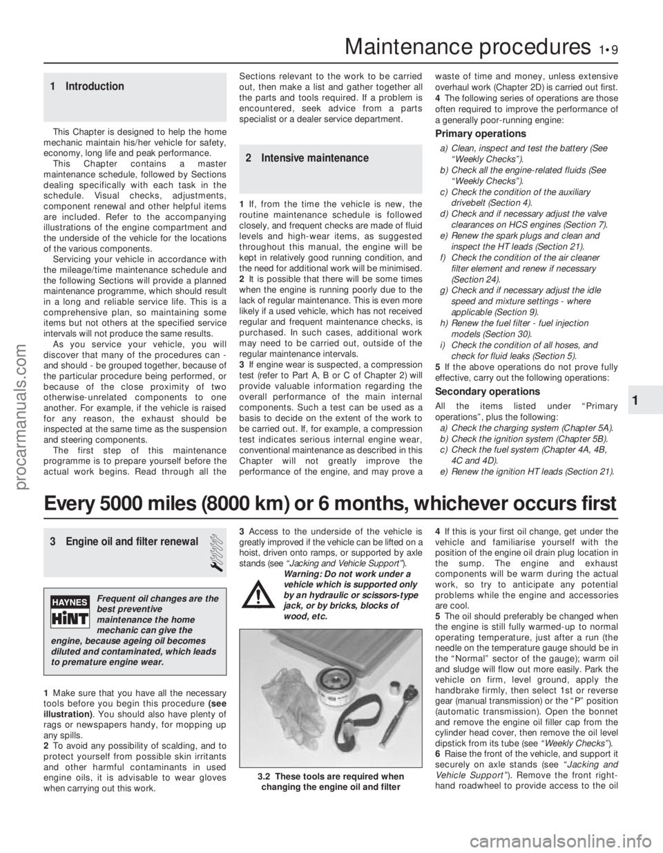
1Make sure that you have all the necessary
tools before you begin this procedure (see
illustration) . You should also have plenty of
rags or newspapers handy, for mopping up
any spills.
2 To avoid any possibility of scalding, and to
protect yourself from possible skin irritants
and other harmful contaminants in used
engine oils, it is advisable to wear gloves
when carrying out this work. 3
Access to the underside of the vehicle is
greatly improved if the vehicle can be lifted on a
hoist, driven onto ramps, or supported by axle
stands (see “Jacking and Vehicle Support” ).
Warning: Do not work under a
vehicle which is supported only
by an hydraulic or scissors-type
jack, or by bricks, blocks of
wood, etc. 4
If this is your first oil change, get under the
vehicle and familiarise yourself with the
position of the engine oil drain plug location in
the sump. The engine and exhaust
components will be warm during the actual
work, so try to anticipate any potential
problems while the engine and accessories
are cool.
5 The oil should preferably be changed when
the engine is still fully warmed-up to normal
operating temperature, just after a run (the
needle on the temperature gauge should be in
the “Normal” sector of the gauge); warm oil
and sludge will flow out more easily. Park the
vehicle on firm, level ground, apply the
handbrake firmly, then select 1st or reverse
gear (manual transmission) or the “P” position
(automatic transmission). Open the bonnet
and remove the engine oil filler cap from the
cylinder head cover, then remove the oil level
dipstick from its tube (see “Weekly Checks”).
6 Raise the front of the vehicle, and support it
securely on axle stands (see “Jacking and
Vehicle Support” ). Remove the front right-
hand roadwheel to provide access to the oil
1 Introduction
This Chapter is designed to help the home
mechanic maintain his/her vehicle for safety,
economy, long life and peak performance.
This Chapter contains a master
maintenance schedule, followed by Sections
dealing specifically with each task in the
schedule. Visual checks, adjustments,
component renewal and other helpful items
are included. Refer to the accompanying
illustrations of the engine compartment and
the underside of the vehicle for the locations
of the various components.
Servicing your vehicle in accordance with
the mileage/time maintenance schedule and
the following Sections will provide a planned
maintenance programme, which should result
in a long and reliable service life. This is a
comprehensive plan, so maintaining some
items but not others at the specified service
intervals will not produce the same results. As you service your vehicle, you will
discover that many of the procedures can -
and should - be grouped together, because of
the particular procedure being performed, or
because of the close proximity of two
otherwise-unrelated components to one
another. For example, if the vehicle is raised
for any reason, the exhaust should be
inspected at the same time as the suspension
and steering components.
The first step of this maintenance
programme is to prepare yourself before the
actual work begins. Read through all the Sections relevant to the work to be carried
out, then make a list and gather together all
the parts and tools required. If a problem is
encountered, seek advice from a parts
specialist or a dealer service department.
2 Intensive maintenance
1
If, from the time the vehicle is new, the
routine maintenance schedule is followed
closely, and frequent checks are made of fluid
levels and high-wear items, as suggested
throughout this manual, the engine will be
kept in relatively good running condition, and
the need for additional work will be minimised.
2 It is possible that there will be some times
when the engine is running poorly due to the
lack of regular maintenance. This is even more
likely if a used vehicle, which has not received
regular and frequent maintenance checks, is
purchased. In such cases, additional work
may need to be carried out, outside of the
regular maintenance intervals.
3 If engine wear is suspected, a compression
test (refer to Part A, B or C of Chapter 2) will
provide valuable information regarding the
overall performance of the main internal
components. Such a test can be used as a
basis to decide on the extent of the work to
be carried out. If, for example, a compression
test indicates serious internal engine wear,
conventional maintenance as described in this
Chapter will not greatly improve the
performance of the engine, and may prove a waste of time and money, unless extensive
overhaul work (Chapter 2D) is carried out first.
4
The following series of operations are those
often required to improve the performance of
a generally poor-running engine:
Primary operations
a) Clean, inspect and test the battery (See
“Weekly Checks”).
b) Check all the engine-related fluids (See
“Weekly Checks”).
c) Check the condition of the auxiliary drivebelt (Section 4).
d) Check and if necessary adjust the valve
clearances on HCS engines (Section 7).
e) Renew the spark plugs and clean and inspect the HT leads (Section 21).
f) Check the condition of the air cleaner filter element and renew if necessary
(Section 24).
g) Check and if necessary adjust the idle speed and mixture settings - where
applicable (Section 9).
h) Renew the fuel filter - fuel injection models (Section 30).
i) Check the condition of all hoses, and check for fluid leaks (Section 5).
5 If the above operations do not prove fully
effective, carry out the following operations:
Secondary operations
All the items listed under “Primary
operations”, plus the following: a) Check the charging system (Chapter 5A).
b) Check the ignition system (Chapter 5B).
c) Check the fuel system (Chapter 4A, 4B,
4C and 4D).
e) Renew the ignition HT leads (Section 21).
Maintenance procedures1•9
3.2 These tools are required when changing the engine oil and filter
1
1595Ford Fiesta Remake
Every 5000 miles (8000 km) or 6 months, whichever occurs first
Frequent oil changes are the
best preventive
maintenance the home
mechanic can give the
engine, because ageing oil becomes
diluted and contaminated, which leads
to premature engine wear.
procarmanuals.com
http://vnx.su
Page 15 of 296

connections - remake the connections or
renew the leads if a fault is found. Use the
same techniques to ensure that all earth
points in the engine compartment provide
good electrical contact through clean, metal-
to-metal joints, and that all are securely
fastened. (In addition to the earth connection
at the engine lifting eye, and that from the
transmission to the body/battery, there are
others in various places, so check carefully).
8Refer to Section 21 for details of spark plug
(HT) lead checks.
7 Valve clearance adjustment
2
Refer to Chapter 2, Part A.
8 Manual transmission oil level check
1
1The manual transmission does not have a
dipstick. To check the oil level, raise the
vehicle and support it securely on axle stands,
making sure that the vehicle is level. On the
lower front side of the transmission housing,
you will see the filler/level plug. Unscrew and
remove it - an Allen key or bit will probably be
required (see illustration) .
2 With the plug removed, check the oil level.
To do this accurately, make up an oil level
check dipstick from a short length of welding
rod or similar material. Make a 90º bend in the
rod, then mark the downward leg in 5 mm
increments. The dipstick is then inserted
through the filler plug orifice so that the
unmarked leg rests flat on the plug orifice
threads, with the marked leg dipped in the oil.
Withdraw the dipstick and read off the level of
oil.
3 The oil level must be maintained between 0
and 5 mm below the lower edge of the
filler/level plug hole. Top up (if necessary),
using fresh transmission oil of the specified
type and using a syringe, or a plastic bottle
and tube. Refit and tighten the filler/level plug
to the specified torque on completion. 4
The need for regular topping-up can only
be due to a leak, which should be found and
rectified without delay.
5 Regular oil changing is not specified by the
manufacturer’s, but the oil can be drained, if
required, by removing the selector shaft cap
nut and locking assembly.
9 Idle speed and mixture check and adjustment
4
General
1Many of the engines fitted to Fiesta models
are equipped with fuel injection systems of
one sort or another which are entirely
controlled by the engine management system.
On most of these vehicles, it isn’t possible to
make any adjustments to the idle speed or the
mixture settings without specialist test
equipment of a type usually only found at a
Ford dealer or fuel injection specialist.
However, the very nature of these highly-
sophisticated systems means they don’t go
out of tune very often (if ever), so that it’s one
less maintenance operation to worry about.
2 On carburettor engines and 1.6 litre EFi fuel
injection engines, certain checks and
adjustments are necessary as part of the
service requirements, and these are described
below.
Idle speed and mixture check
and adjustment - carburettor
engines
Note: Later carburettors are fitted with
tamperproof mixture adjusting screws,
consisting of a hexagon-shaped socket with a
pin in the centre. Such screws require the use
of Ford service tool 23-032 to alter their
settings; if this tool (or a suitable equivalent) is
not available, the CO level will have to be
checked, and any necessary adjustment will
have to be made, by a Ford dealer.
3 Before carrying out the following checks
and adjustments, ensure that the spark plugs
are in good condition and correctly gapped
(Section 21). To carry out the checks/adjustments, an accurate tachometer
and an exhaust gas analyser (CO meter) will
be required.
4
Make sure that all electrical components
are switched off during the following
procedures.
5 Connect a tachometer to the engine in
accordance with its manufacturer’s
instructions, and insert the probe of an
exhaust gas analyser (CO meter) into the
exhaust tailpipe. As previously mentioned,
these items are essential in obtaining an
accurate setting. If they are not available, an
approximate check/adjustment can be made
as a temporary measure, providing they are
further checked out as soon as is possible
using a tachometer and a CO meter (or by a
Ford dealer).
6 Run the engine at a fast idle speed until it
reaches its normal operating temperature and
the radiator cooling fan cuts in. Turn the
engine off, then disconnect the radiator
cooling fan lead at the thermostatic switch
connector. Now connect a temporary wire to
the fan switch multi-plug, as shown (see
illustration) to enable the fan to operate
continuously during the following checks and
adjustments (if this is specified). Take care to
keep clear of the fan during the following
operations when working in the engine
compartment.
7 Where fitted, disconnect the throttle kicker
vacuum pipe, and plug the end. To identify
the throttle kicker unit, refer to Chapter 4A.
8 Check that the vehicle lighting and other
electrical loadings (apart from the radiator
cooling fan) are switched off, then restart the
engine. Increase the engine speed to 3000 rpm
for 30 seconds, and repeat this at three-minute
intervals during the check/adjustment
procedures. This will ensure that any excess
fuel is cleared from the inlet manifold.
9 Ensure that the throttle is fully released, allow
the meters to stabilise for a period of 5 to
30 seconds is normally sufficient, then check
the idle speed against that specified. If adjust-
ment is necessary, turn the idle speed
adjusting screw until the engine is idling at the
specified speed (see illustrations) . Any checks
and adjustments must be completed within
30 seconds of the meters stabilising.
1•14Every 10 000 miles or 12 months
9.9a Idle speed adjusting screw (A) and
mixture adjusting screw (B) (Weber TLM
carburettor)9.6 Cooling fan thermostatic switch multi-plug with temporary bridging wire
connected8.1 Manual transmission oil level/filler
plug (A), and selector shaft cap nut (B)
1595Ford Fiesta Remakeprocarmanuals.com
http://vnx.su
Page 18 of 296
point at the engine to the end of the tailpipe.
Ideally, this should be done on a hoist, where
unrestricted access is available; if a hoist is
not available, raise and support the vehicle on
axle stands.
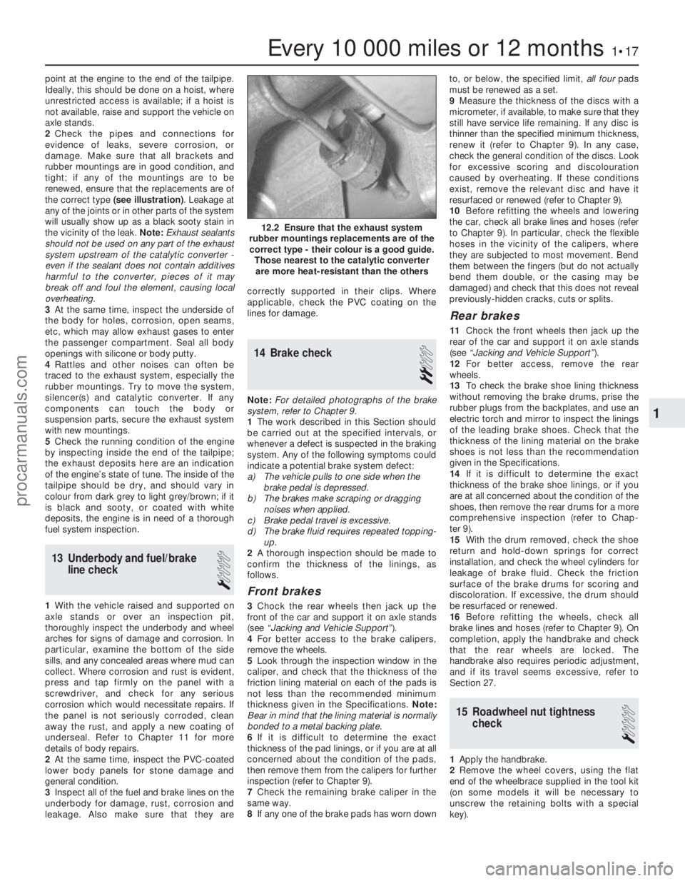
2Check the pipes and connections for
evidence of leaks, severe corrosion, or
damage. Make sure that all brackets and
rubber mountings are in good condition, and
tight; if any of the mountings are to be
renewed, ensure that the replacements are of
the correct type (see illustration) . Leakage at
any of the joints or in other parts of the system
will usually show up as a black sooty stain in
the vicinity of the leak. Note: Exhaust sealants
should not be used on any part of the exhaust
system upstream of the catalytic converter -
even if the sealant does not contain additives
harmful to the converter, pieces of it may
break off and foul the element, causing local
overheating.
3 At the same time, inspect the underside of
the body for holes, corrosion, open seams,
etc, which may allow exhaust gases to enter
the passenger compartment. Seal all body
openings with silicone or body putty.
4 Rattles and other noises can often be
traced to the exhaust system, especially the
rubber mountings. Try to move the system,
silencer(s) and catalytic converter. If any
components can touch the body or
suspension parts, secure the exhaust system
with new mountings.
5 Check the running condition of the engine
by inspecting inside the end of the tailpipe;
the exhaust deposits here are an indication
of the engine’s state of tune. The inside of the
tailpipe should be dry, and should vary in
colour from dark grey to light grey/brown; if it
is black and sooty, or coated with white
deposits, the engine is in need of a thorough
fuel system inspection.
13 Underbody and fuel/brake line check
1
1With the vehicle raised and supported on
axle stands or over an inspection pit,
thoroughly inspect the underbody and wheel
arches for signs of damage and corrosion. In
particular, examine the bottom of the side
sills, and any concealed areas where mud can
collect. Where corrosion and rust is evident,
press and tap firmly on the panel with a
screwdriver, and check for any serious
corrosion which would necessitate repairs. If
the panel is not seriously corroded, clean
away the rust, and apply a new coating of
underseal. Refer to Chapter 11 for more
details of body repairs.
2 At the same time, inspect the PVC-coated
lower body panels for stone damage and
general condition.
3 Inspect all of the fuel and brake lines on the
underbody for damage, rust, corrosion and
leakage. Also make sure that they are correctly supported in their clips. Where
applicable, check the PVC coating on the
lines for damage.
14 Brake check
2
Note:
For detailed photographs of the brake
system, refer to Chapter 9.
1 The work described in this Section should
be carried out at the specified intervals, or
whenever a defect is suspected in the braking
system. Any of the following symptoms could
indicate a potential brake system defect:
a) The vehicle pulls to one side when the brake pedal is depressed.
b) The brakes make scraping or dragging
noises when applied.
c) Brake pedal travel is excessive.
d) The brake fluid requires repeated topping-
up.
2 A thorough inspection should be made to
confirm the thickness of the linings, as
follows.
Front brakes
3 Chock the rear wheels then jack up the
front of the car and support it on axle stands
(see “Jacking and Vehicle Support” ).
4 For better access to the brake calipers,
remove the wheels.
5 Look through the inspection window in the
caliper, and check that the thickness of the
friction lining material on each of the pads is
not less than the recommended minimum
thickness given in the Specifications. Note:
Bear in mind that the lining material is normally
bonded to a metal backing plate.
6 If it is difficult to determine the exact
thickness of the pad linings, or if you are at all
concerned about the condition of the pads,
then remove them from the calipers for further
inspection (refer to Chapter 9).
7 Check the remaining brake caliper in the
same way.
8 If any one of the brake pads has worn down to, or below, the specified limit,
all fourpads
must be renewed as a set.
9 Measure the thickness of the discs with a
micrometer, if available, to make sure that they
still have service life remaining. If any disc is
thinner than the specified minimum thickness,
renew it (refer to Chapter 9). In any case,
check the general condition of the discs. Look
for excessive scoring and discolouration
caused by overheating. If these conditions
exist, remove the relevant disc and have it
resurfaced or renewed (refer to Chapter 9).
10 Before refitting the wheels and lowering
the car, check all brake lines and hoses (refer
to Chapter 9). In particular, check the flexible
hoses in the vicinity of the calipers, where
they are subjected to most movement. Bend
them between the fingers (but do not actually
bend them double, or the casing may be
damaged) and check that this does not reveal
previously-hidden cracks, cuts or splits.
Rear brakes
11 Chock the front wheels then jack up the
rear of the car and support it on axle stands
(see “Jacking and Vehicle Support” ).
12 For better access, remove the rear
wheels.
13 To check the brake shoe lining thickness
without removing the brake drums, prise the
rubber plugs from the backplates, and use an
electric torch and mirror to inspect the linings
of the leading brake shoes. Check that the
thickness of the lining material on the brake
shoes is not less than the recommendation
given in the Specifications.
14 If it is difficult to determine the exact
thickness of the brake shoe linings, or if you
are at all concerned about the condition of the
shoes, then remove the rear drums for a more
comprehensive inspection (refer to Chap-
ter 9).
15 With the drum removed, check the shoe
return and hold-down springs for correct
installation, and check the wheel cylinders for
leakage of brake fluid. Check the friction
surface of the brake drums for scoring and
discoloration. If excessive, the drum should
be resurfaced or renewed.
16 Before refitting the wheels, check all
brake lines and hoses (refer to Chapter 9). On
completion, apply the handbrake and check
that the rear wheels are locked. The
handbrake also requires periodic adjustment,
and if its travel seems excessive, refer to
Section 27.
15 Roadwheel nut tightness check
1
1Apply the handbrake.
2 Remove the wheel covers, using the flat
end of the wheelbrace supplied in the tool kit
(on some models it will be necessary to
unscrew the retaining bolts with a special
key).
Every 10 000 miles or 12 months1•17
12.2 Ensure that the exhaust system
rubber mountings replacements are of the correct type - their colour is a good guide. Those nearest to the catalytic converterare more heat-resistant than the others
1
1595Ford Fiesta Remakeprocarmanuals.com
http://vnx.su
Page 20 of 296
21 Spark plug renewal and HTcomponent check
1
Note: Spark plug renewal at this service
interval is only necessary on the HCS, CVH
and PTE engines. On Zetec engines, the
recommended interval for spark plug renewal
is every 30 000 miles or three years.
Spark plug check and renewal
1 It is vital for the correct running, full
performance and proper economy of the engine
that the spark plugs perform with maximum
efficiency. The most important factor in ensuring
this is that the plugs fitted are appropriate for the
engine. The suitable type is given in the
Specifications Section at the beginning of this
Chapter, on the Vehicle Emissions Control
Information (VECI) label located on the
underside of the bonnet (only on models sold in
some areas) or in the vehicle’s Owner’s
Handbook. If the correct type is used and the
engine is in good condition, the spark plugs
should not need attention between scheduled
renewal intervals. Spark plug cleaning is rarely
necessary, and should not be attempted unless
specialised equipment is available, as damage
can easily be caused to the firing ends.
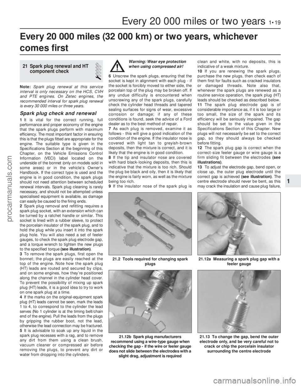
2 Spark plug removal and refitting requires a
spark plug socket, with an extension which can
be turned by a ratchet handle or similar. This
socket is lined with a rubber sleeve, to protect
the porcelain insulator of the spark plug, and to
hold the plug while you insert it into the spark
plug hole. You will also need a set of feeler
gauges, to check the spark plug electrode gap,
and a torque wrench to tighten the new plugs
to the specified torque (see illustration).
3 To remove the spark plugs, first open the
bonnet; the plugs are easily reached at the
top of the engine. Note how the spark plug
(HT) leads are routed and secured by clips,
and on some engines, how they’re positioned
along the channel in the cylinder head cover.
To prevent the possibility of mixing up spark
plug (HT) leads, it is a good idea to try to work
on one spark plug at a time.
4 If the marks on the original-equipment spark
plug (HT) leads cannot be seen, mark the leads
1 to 4, to correspond to the cylinder the lead
serves (No 1 cylinder is at the timing belt/chain
end of the engine). Pull the leads from the plugs
by gripping the rubber boot, not the lead,
otherwise the lead connection may be fractured.
5 It is advisable to soak up any liquid in the
spark plug recesses with a rag, and to remove
any dirt from them using a clean brush,
vacuum cleaner or compressed air before
removing the plugs, to prevent any dirt or
water from dropping into the cylinders. Warning: Wear eye protection
when using compressed air!
6 Unscrew the spark plugs, ensuring that the
socket is kept in alignment with each plug - if
the socket is forcibly moved to either side, the
porcelain top of the plug may be broken off. If
any undue difficulty is encountered when
unscrewing any of the spark plugs, carefully
check the cylinder head threads and tapered
sealing surfaces for signs of wear, excessive
corrosion or damage; if any of these
conditions is found, seek the advice of a Ford
dealer as to the best method of repair.
7 As each plug is removed, examine it as
follows - this will give a good indication of the
condition of the engine. If the insulator nose is
covered with light tan to greyish-brown
deposits, then the mixture is correct, and it is
likely that the engine is in good condition.
8 If the tip and insulator nose are covered
with hard black-looking deposits, then this is
indicative that the mixture is too rich. Should
the plug be black and oily, then it is likely that
the engine is fairly worn, as well as the mixture
being too rich.
9 If the insulator nose of the spark plug is clean and white, with no deposits, this is
indicative of a weak mixture.
10
If you are renewing the spark plugs,
purchase the new plugs, then check each of
them first for faults such as cracked insulators
or damaged threads. Note also that,
whenever the spark plugs are renewed as a
routine service operation, the spark plug (HT)
leads should be checked as described below.
11 The spark plug electrode gap is of
considerable importance as, if it is too large or
too small, the size of the spark and its
efficiency will be seriously impaired. The gap
should be set to the value given in the
Specifications Section of this Chapter. New
plugs will not necessarily be set to the correct
gap, so they should always be checked
before fitting.
12 The spark plug gap is correct when the
correct-size feeler gauge or wire gauge is a
firm sliding fit between the electrodes (see
illustrations) .
13 To adjust the electrode gap, bend open, or
close up, the outer plug electrode until the
correct gap is achieved (see illustration). The
centre electrode should never be bent, as this
may crack the insulation and cause plug failure,
Every 20 000 miles (32 000 km) or two years, whichever
comes first
Every 20 000 miles or two years1•19
21.12b Spark plug manufacturers
recommend using a wire-type gauge when
checking the gap - if the wire or feeler gauge
does not slide between the electrodes with a slight drag, adjustment is required
21.12a Measuring a spark plug gap with a feeler gauge21.2 Tools required for changing spark plugs
21.13 To change the gap, bend the outer
electrode only, and be very careful not to crack or chip the porcelain insulator
surrounding the centre electrode
1
1595Ford Fiesta Remakeprocarmanuals.com
http://vnx.su
Page 24 of 296
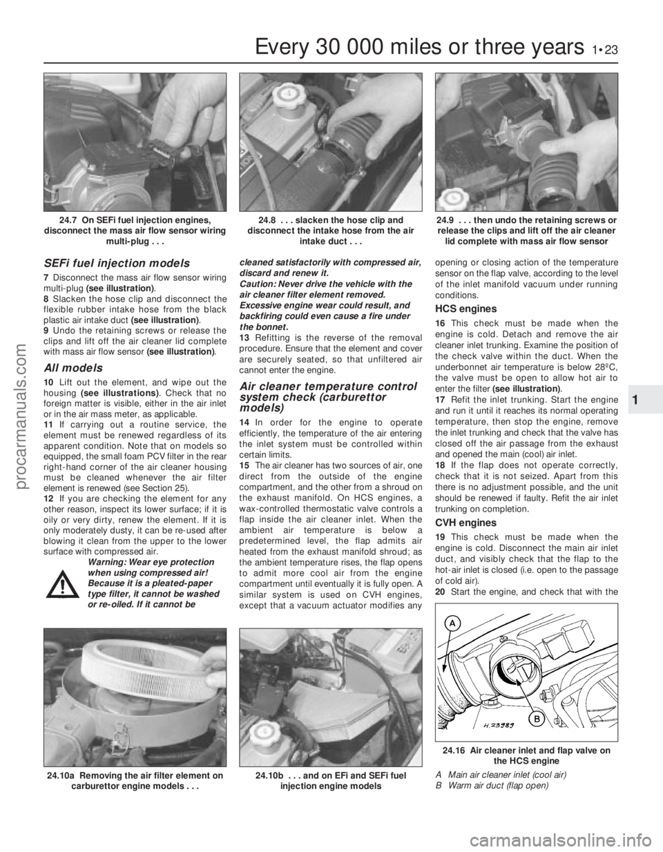
SEFi fuel injection models
7Disconnect the mass air flow sensor wiring
multi-plug (see illustration) .
8 Slacken the hose clip and disconnect the
flexible rubber intake hose from the black
plastic air intake duct (see illustration).
9 Undo the retaining screws or release the
clips and lift off the air cleaner lid complete
with mass air flow sensor (see illustration).
All models
10Lift out the element, and wipe out the
housing (see illustrations) . Check that no
foreign matter is visible, either in the air inlet
or in the air mass meter, as applicable.
11 If carrying out a routine service, the
element must be renewed regardless of its
apparent condition. Note that on models so
equipped, the small foam PCV filter in the rear
right-hand corner of the air cleaner housing
must be cleaned whenever the air filter
element is renewed (see Section 25).
12 If you are checking the element for any
other reason, inspect its lower surface; if it is
oily or very dirty, renew the element. If it is
only moderately dusty, it can be re-used after
blowing it clean from the upper to the lower
surface with compressed air. Warning: Wear eye protection
when using compressed air!
Because it is a pleated-paper
type filter, it cannot be washed
or re-oiled. If it cannot be cleaned satisfactorily with compressed air,
discard and renew it.
Caution: Never drive the vehicle with the
air cleaner filter element removed.
Excessive engine wear could result, and
backfiring could even cause a fire under
the bonnet.
13
Refitting is the reverse of the removal
procedure. Ensure that the element and cover
are securely seated, so that unfiltered air
cannot enter the engine.Air cleaner temperature control
system check (carburettor
models)
14 In order for the engine to operate
efficiently, the temperature of the air entering
the inlet system must be controlled within
certain limits.
15 The air cleaner has two sources of air, one
direct from the outside of the engine
compartment, and the other from a shroud on
the exhaust manifold. On HCS engines, a
wax-controlled thermostatic valve controls a
flap inside the air cleaner inlet. When the
ambient air temperature is below a
predetermined level, the flap admits air
heated from the exhaust manifold shroud; as
the ambient temperature rises, the flap opens
to admit more cool air from the engine
compartment until eventually it is fully open. A
similar system is used on CVH engines,
except that a vacuum actuator modifies any opening or closing action of the temperature
sensor on the flap valve, according to the level
of the inlet manifold vacuum under running
conditions.
HCS engines
16
This check must be made when the
engine is cold. Detach and remove the air
cleaner inlet trunking. Examine the position of
the check valve within the duct. When the
underbonnet air temperature is below 28ºC,
the valve must be open to allow hot air to
enter the filter (see illustration) .
17 Refit the inlet trunking. Start the engine
and run it until it reaches its normal operating
temperature, then stop the engine, remove
the inlet trunking and check that the valve has
closed off the air passage from the exhaust
and opened the main (cool) air inlet.
18 If the flap does not operate correctly,
check that it is not seized. Apart from this
there is no adjustment possible, and the unit
should be renewed if faulty. Refit the air inlet
trunking on completion.
CVH engines
19 This check must be made when the
engine is cold. Disconnect the main air inlet
duct, and visibly check that the flap to the
hot-air inlet is closed (i.e. open to the passage
of cold air).
20 Start the engine, and check that with the
Every 30 000 miles or three years1•23
24.9 . . . then undo the retaining screws or
release the clips and lift off the air cleaner lid complete with mass air flow sensor24.8 . . . slacken the hose clip and
disconnect the intake hose from the air intake duct . . .24.7 On SEFi fuel injection engines,
disconnect the mass air flow sensor wiring multi-plug . . .
24.16 Air cleaner inlet and flap valve onthe HCS engine
A Main air cleaner inlet (cool air)
B Warm air duct (flap open)
24.10b . . . and on EFi and SEFi fuel injection engine models24.10a Removing the air filter element oncarburettor engine models . . .
1
1595Ford Fiesta Remakeprocarmanuals.com
http://vnx.su
Page 36 of 296
8Fit a new oil filter into position on
the oil pump body, as described in Chap-
ter 1.
9 Lower the vehicle to the ground, and top-
up the engine oil as described in “Weekly
Checks”.
13 Oil pump - dismantling,
inspection and reassembly
3
Dismantling
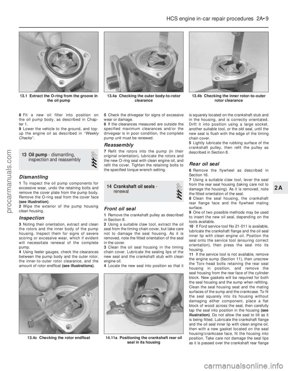
1 To inspect the oil pump components for
excessive wear, undo the retaining bolts and
remove the cover plate from the pump body.
Remove the O-ring seal from the cover face
(see illustration) .
2 Wipe the exterior of the pump housing
clean housing.
Inspection
3 Noting their orientation, extract and clean
the rotors and the inner body of the pump
housing. Inspect them for signs of severe
scoring or excessive wear, which if evident
will necessitate renewal of the complete
pump.
4 Using feeler gauges, check the clearances
between the pump body and the outer rotor,
the inner-to-outer rotor clearance, and the
amount of rotor endfloat (see illustrations).5
Check the drivegear for signs of excessive
wear or damage.
6 If the clearances measured are outside the
specified maximum clearances and/or the
drivegear is in poor condition, the complete
pump unit must be renewed.
Reassembly
7 Refit the rotors into the pump (in their
original orientation), lubricate the rotors and
the new O-ring seal with clean engine oil, and
refit the cover. Tighten the retaining bolts to
the specified torque wrench setting.
14 Crankshaft oil seals -
renewal
3
Front oil seal
1 Remove the crankshaft pulley as described
in Section 8.
2 Using a suitable claw tool, extract the oil
seal from the timing chain cover, but take care
not to damage the seal housing. As it is
removed, note the fitted orientation of the seal
in the cover.
3 Clean the oil seal housing in the timing
chain cover. Lubricate the sealing lips of the
new seal and the crankshaft stub with clean
engine oil.
4 Locate the new seal into position so that it is squarely located on the crankshaft stub and
in the housing, and is correctly orientated.
Drift it into position using a large socket,
another suitable tool, or the old seal, until the
new seal is flush with the edge of the timing
chain cover.
5
Lightly lubricate the rubbing surface of the
crankshaft pulley, then refit the pulley as
described in Section 8.
Rear oil seal
6 Remove the flywheel as described in
Section 16.
7 Using a suitable claw tool, lever the seal
from the rear seal housing (taking care not to
damage the housing). As it is removed, note
the fitted orientation of the seal.
8 Clean the seal housing, the crankshaft
rear flange face and the flywheel mating
surface.
9 One of two possible methods may be used
to insert the new oil seal, depending on the
tools available.
10 If Ford service tool No 21-011 is available,
lubricate the crankshaft flange and the oil seal
inner lip with clean engine oil. Position the
seal onto the service tool (ensuring correct
orientation), then press the seal into its
housing.
11 If the service tool is not available, remove
the engine sump (Section 11), then unscrew
the Torx-head bolts retaining the rear seal
housing in position, and remove the
seal housing from the rear face of the cylinder
block. New gaskets will be required for both
the seal housing and the sump when refitting.
Clean the seal housing seat and the mating
surfaces of the sump and the crankcase. To fit
the seal squarely into its housing without
damaging either component, place a flat
block of wood across the seal, then carefully
tap the seal into position in the housing (see
illustration) . Do not allow the seal to tilt as it
is being fitted. Lubricate the crankshaft flange
and the oil seal inner lip with clean engine oil,
then with a new gasket located on the seal
housing/crankcase face, fit the housing into
position. Take care not damage the seal lips
as it is passed over the crankshaft rear flange
HCS engine in-car repair procedures 2A•9
13.4b Checking the inner rotor-to-outer rotor clearance13.4a Checking the outer body-to-rotor clearance13.1 Extract the O-ring from the groove inthe oil pump
14.11a Positioning the crankshaft rear oilseal in its housing13.4c Checking the rotor endfloat
2A
1595Ford Fiesta Remakeprocarmanuals.com
http://vnx.su
Page 52 of 296
its housing. If the seal housing is removed
from the rear face of the engine, the seal can
be removed as described in paragraph 18. As
it is removed, note the direction of fitting, and
take care not to damage the seal housing as
the seal is extracted.
14Clean the seal housing, the crankshaft
rear flange face, and the flywheel/driveplate
mating surfaces.
15 One of two possible methods may be
used to insert the new oil seal, depending on
the tools available.
16 If Ford special service tool No 21-095 is
available, lubricate the seal lips of the seal and
its running face on the crankshaft with clean
engine oil. Position the seal (correctly
orientated) into the special tool, then draw the
seal into the housing using two
flywheel/driveplate securing bolts so that the
seal is against the stop.
17 If the correct Ford service tool is not
available, it will be necessary to remove the oil
seal carrier housing. To do this, first remove
the sump as described in Section 13, then
unscrew the seal housing retaining bolts and
remove the housing from the rear face of the
crankcase.
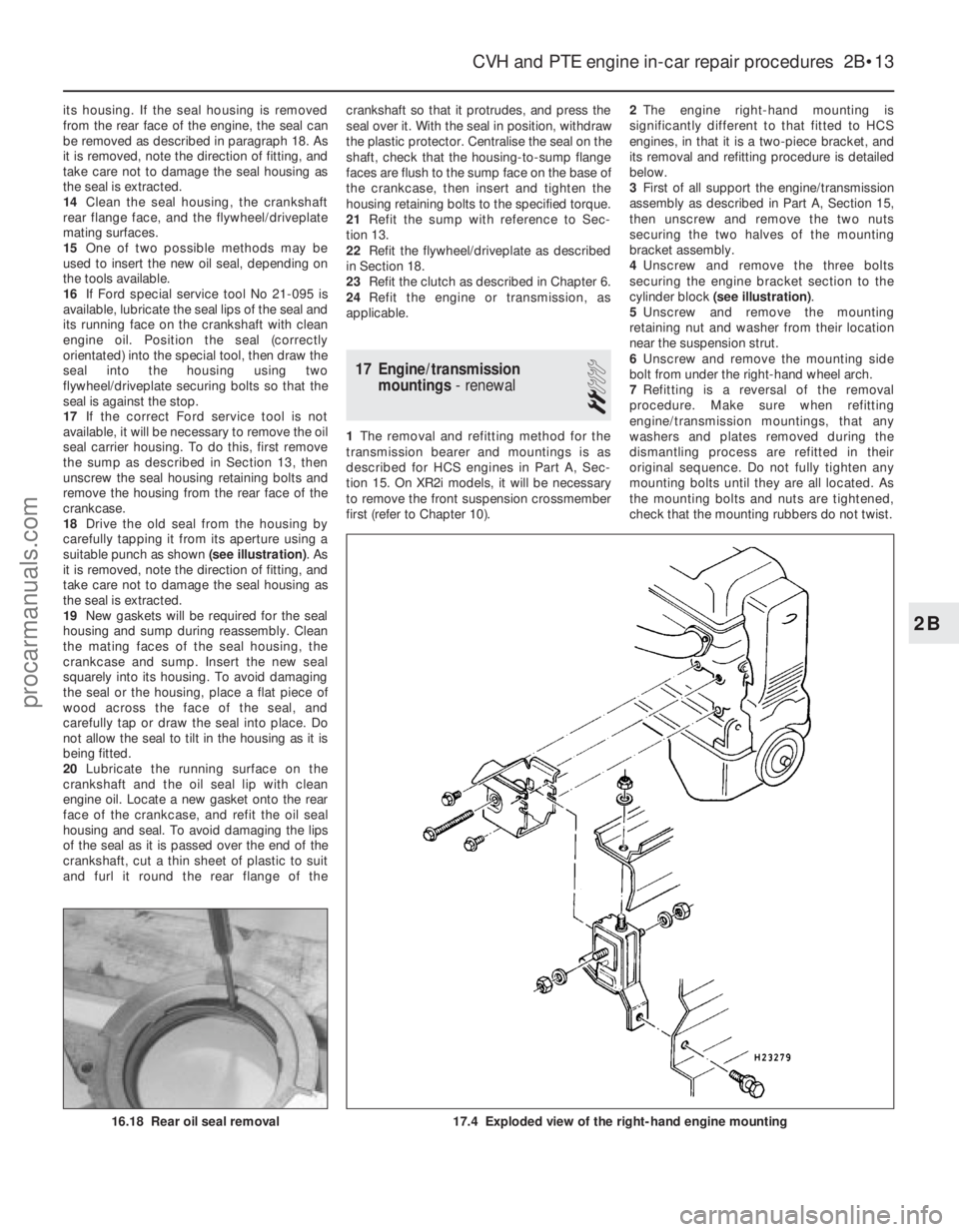
18 Drive the old seal from the housing by
carefully tapping it from its aperture using a
suitable punch as shown (see illustration). As
it is removed, note the direction of fitting, and
take care not to damage the seal housing as
the seal is extracted.
19 New gaskets will be required for the seal
housing and sump during reassembly. Clean
the mating faces of the seal housing, the
crankcase and sump. Insert the new seal
squarely into its housing. To avoid damaging
the seal or the housing, place a flat piece of
wood across the face of the seal, and
carefully tap or draw the seal into place. Do
not allow the seal to tilt in the housing as it is
being fitted.
20 Lubricate the running surface on the
crankshaft and the oil seal lip with clean
engine oil. Locate a new gasket onto the rear
face of the crankcase, and refit the oil seal
housing and seal. To avoid damaging the lips
of the seal as it is passed over the end of the
crankshaft, cut a thin sheet of plastic to suit
and furl it round the rear flange of the crankshaft so that it protrudes, and press the
seal over it. With the seal in position, withdraw
the plastic protector. Centralise the seal on the
shaft, check that the housing-to-sump flange
faces are flush to the sump face on the base of
the crankcase, then insert and tighten the
housing retaining bolts to the specified torque.
21
Refit the sump with reference to Sec-
tion 13.
22 Refit the flywheel/driveplate as described
in Section 18.
23 Refit the clutch as described in Chapter 6.
24 Refit the engine or transmission, as
applicable.
17 Engine/transmission mountings - renewal
2
1The removal and refitting method for the
transmission bearer and mountings is as
described for HCS engines in Part A, Sec-
tion 15. On XR2i models, it will be necessary
to remove the front suspension crossmember
first (refer to Chapter 10). 2
The engine right-hand mounting is
significantly different to that fitted to HCS
engines, in that it is a two-piece bracket, and
its removal and refitting procedure is detailed
below.
3 First of all support the engine/transmission
assembly as described in Part A, Section 15,
then unscrew and remove the two nuts
securing the two halves of the mounting
bracket assembly.
4 Unscrew and remove the three bolts
securing the engine bracket section to the
cylinder block (see illustration) .
5 Unscrew and remove the mounting
retaining nut and washer from their location
near the suspension strut.
6 Unscrew and remove the mounting side
bolt from under the right-hand wheel arch.
7 Refitting is a reversal of the removal
procedure. Make sure when refitting
engine/transmission mountings, that any
washers and plates removed during the
dismantling process are refitted in their
original sequence. Do not fully tighten any
mounting bolts until they are all located. As
the mounting bolts and nuts are tightened,
check that the mounting rubbers do not twist.
CVH and PTE engine in-car repair procedures 2B•13
17.4 Exploded view of the right-hand engine mounting16.18 Rear oil seal removal
2B
1595Ford Fiesta Remakeprocarmanuals.com
http://vnx.su
Page 57 of 296
clamp brackets and disconnect the pipe joint
union over the top of the cylinder head cover.
Place absorbent rags beneath the union as it
is disconnected to soak up escaping fluid and
plug the open unions to prevent dirt entry and
further fluid loss. Move the pipe(s) clear just
sufficiently to allow removal of the cylinder
head cover.
5Remove the timing belt upper cover (see
Section 7).
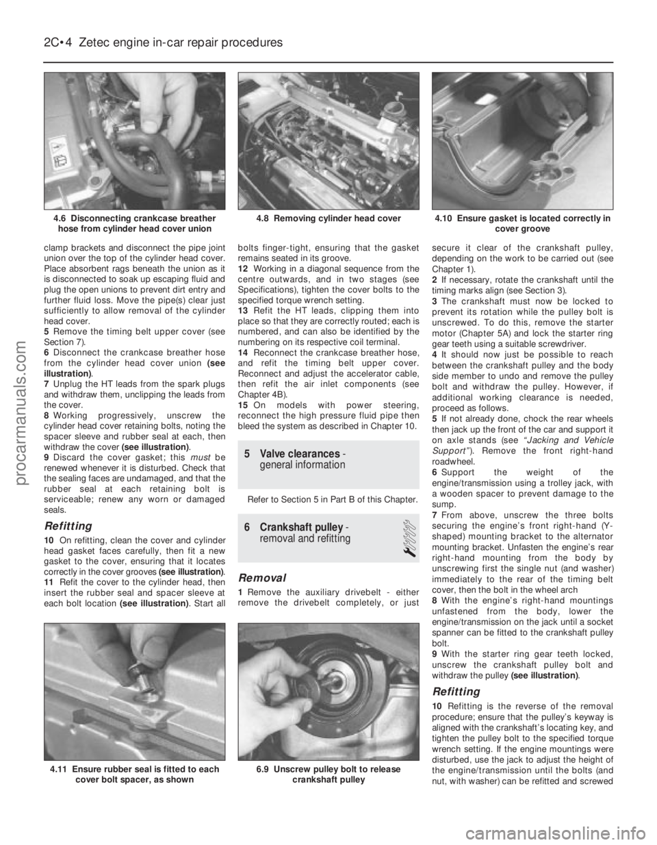
6 Disconnect the crankcase breather hose
from the cylinder head cover union (see
illustration) .
7 Unplug the HT leads from the spark plugs
and withdraw them, unclipping the leads from
the cover.
8 Working progressively, unscrew the
cylinder head cover retaining bolts, noting the
spacer sleeve and rubber seal at each, then
withdraw the cover (see illustration).
9 Discard the cover gasket; this mustbe
renewed whenever it is disturbed. Check that
the sealing faces are undamaged, and that the
rubber seal at each retaining bolt is
serviceable; renew any worn or damaged
seals.
Refitting
10 On refitting, clean the cover and cylinder
head gasket faces carefully, then fit a new
gasket to the cover, ensuring that it locates
correctly in the cover grooves (see illustration).
11 Refit the cover to the cylinder head, then
insert the rubber seal and spacer sleeve at
each bolt location (see illustration). Start allbolts finger-tight, ensuring that the gasket
remains seated in its groove.
12
Working in a diagonal sequence from the
centre outwards, and in two stages (see
Specifications), tighten the cover bolts to the
specified torque wrench setting.
13 Refit the HT leads, clipping them into
place so that they are correctly routed; each is
numbered, and can also be identified by the
numbering on its respective coil terminal.
14 Reconnect the crankcase breather hose,
and refit the timing belt upper cover.
Reconnect and adjust the accelerator cable,
then refit the air inlet components (see
Chapter 4B).
15 On models with power steering,
reconnect the high pressure fluid pipe then
bleed the system as described in Chapter 10.
5 Valve clearances -
general information
Refer to Section 5 in Part B of this Chapter.
6 Crankshaft pulley -
removal and refitting
1
Removal
1 Remove the auxiliary drivebelt - either
remove the drivebelt completely, or just secure it clear of the crankshaft pulley,
depending on the work to be carried out (see
Chapter 1).
2
If necessary, rotate the crankshaft until the
timing marks align (see Section 3).
3 The crankshaft must now be locked to
prevent its rotation while the pulley bolt is
unscrewed. To do this, remove the starter
motor (Chapter 5A) and lock the starter ring
gear teeth using a suitable screwdriver.
4 It should now just be possible to reach
between the crankshaft pulley and the body
side member to undo and remove the pulley
bolt and withdraw the pulley. However, if
additional working clearance is needed,
proceed as follows.
5 If not already done, chock the rear wheels
then jack up the front of the car and support it
on axle stands (see “Jacking and Vehicle
Support” ). Remove the front right-hand
roadwheel.
6 Support the weight of the
engine/transmission using a trolley jack, with
a wooden spacer to prevent damage to the
sump.
7 From above, unscrew the three bolts
securing the engine’s front right-hand (Y-
shaped) mounting bracket to the alternator
mounting bracket. Unfasten the engine’s rear
right-hand mounting from the body by
unscrewing first the single nut (and washer)
immediately to the rear of the timing belt
cover, then the bolt in the wheel arch
8 With the engine’s right-hand mountings
unfastened from the body, lower the
engine/transmission on the jack until a socket
spanner can be fitted to the crankshaft pulley
bolt.
9 With the starter ring gear teeth locked,
unscrew the crankshaft pulley bolt and
withdraw the pulley (see illustration).
Refitting
10Refitting is the reverse of the removal
procedure; ensure that the pulley’s keyway is
aligned with the crankshaft’s locating key, and
tighten the pulley bolt to the specified torque
wrench setting. If the engine mountings were
disturbed, use the jack to adjust the height of
the engine/transmission until the bolts (and
nut, with washer) can be refitted and screwed
2C•4 Zetec engine in-car repair procedures
6.9 Unscrew pulley bolt to release
crankshaft pulley4.11 Ensure rubber seal is fitted to eachcover bolt spacer, as shown
4.10 Ensure gasket is located correctly in cover groove4.8 Removing cylinder head cover
1595Ford Fiesta Remake
4.6 Disconnecting crankcase breather
hose from cylinder head cover unionprocarmanuals.com
http://vnx.su
Page 58 of 296
home by hand, then tighten them securely, to
the specified torque wrench settings, where
given.
11Refit the auxiliary drivebelt as described in
Chapter 1 on completion.
7 Timing belt covers -
removal and refitting
4
Upper cover
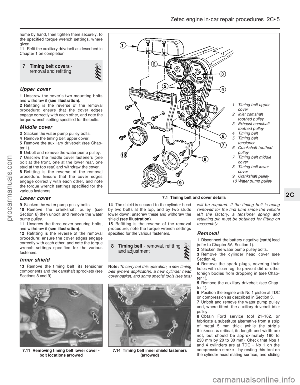
1 Unscrew the cover’s two mounting bolts
and withdraw it (see illustration) .
2 Refitting is the reverse of the removal
procedure; ensure that the cover edges
engage correctly with each other, and note the
torque wrench setting specified for the bolts.
Middle cover
3 Slacken the water pump pulley bolts.
4 Remove the timing belt upper cover.
5 Remove the auxiliary drivebelt (see Chap-
ter 1).
6 Unbolt and remove the water pump pulley.
7 Unscrew the middle cover fasteners (one
bolt at the front, one at the lower rear, one
stud at the top rear) and withdraw the cover.
8 Refitting is the reverse of the removal
procedure. Ensure that the cover edges
engage correctly with each other, and note
the torque wrench settings specified for the
various fasteners.
Lower cover
9 Slacken the water pump pulley bolts.
10 Remove the crankshaft pulley (see
Section 6) then unbolt and remove the water
pump pulley.
11 Unscrew the three cover securing bolts,
and withdraw it (see illustration) .
12 Refitting is the reverse of the removal
procedure; ensure the cover edges engage
correctly with each other, and note the torque
wrench settings specified for the various
fasteners.
Inner shield
13 Remove the timing belt, its tensioner
components and the camshaft sprockets (see
Sections 8 and 9). 14
The shield is secured to the cylinder head
by two bolts at the top, and by two studs
lower down; unscrew these and withdraw the
shield (see illustration) .
15 Refitting is the reverse of the removal
procedure; note the torque wrench settings
specified for the various fasteners.
8 Timing belt - removal, refitting
and adjustment
4
Note: To carry out this operation, a new timing
belt (where applicable), a new cylinder head
cover gasket, and some special tools (see text) will be required. If the timing belt is being
removed for the first time since the vehicle
left the factory, a tensioner spring and
retaining pin must be obtained for fitting on
reassembly.
Removal
1
Disconnect the battery negative (earth) lead
(refer to Chapter 5A, Section 1).
2 Slacken the water pump pulley bolts.
3 Remove the cylinder head cover (see
Section 4).
4 Remove the spark plugs, covering their
holes with clean rag, to prevent dirt or other
foreign bodies from dropping in (see Chap-
ter 1).
5 Remove the auxiliary drivebelt (see Chap-
ter 1).
6 Position the engine with No 1 piston at TDC
on compression as described in Section 3.
7 Unbolt and remove the water pump pulley
and, where fitted, the auxiliary drivebelt idler
pulley.
8 Obtain Ford service tool 21-162, or
fabricate a substitute alternative from a strip
of metal 5 mm thick (while the strip’s
thickness iscritical, its length and width are
not, but should be approximately 180 to
230 mm by 20 to 30 mm). Check that Nos 1
and 4 cylinders are at TDC - No 1 on the
compression stroke - by resting this tool on
the cylinder head mating surface, and sliding
Zetec engine in-car repair procedures 2C•5
7.11 Removing timing belt lower cover - bolt locations arrowed7.14 Timing belt inner shield fasteners (arrowed)
7.1 Timing belt and cover details2C
1595Ford Fiesta Remake 1 Timing belt upper
cover
2 Inlet camshaft
toothed pulley
3 Exhaust camshaft
toothed pulley
4 Timing belt
5 Timing belt
tensioner
6 Crankshaft toothed pulley
7 Timing belt middle cover
8 Timing belt lower
cover
9 Crankshaft pulley
10 Water pump pulleyprocarmanuals.com
http://vnx.su