FORD FIESTA 2007 Workshop Manual
Manufacturer: FORD, Model Year: 2007, Model line: FIESTA, Model: FORD FIESTA 2007Pages: 1226, PDF Size: 61.26 MB
Page 1181 of 1226
309-00-5 Exhaust System 309-00-5
DESCRIPTION AND OPERATION
All exhaust systems are single-part systems. The
final muffler can be renewed separately in service.
1 In this case the pipe needs to be cut through, and
the new final muffler needs to be secured with a
servicing clamp.
2006.0 Fiesta 1212006 GI 67275en
procarmanuals.com
Page 1182 of 1226

309-00-6 Exhaust System 309-00-6
REMOVAL AND INSTALLATION
Catalytic Converter - 2.OL Duratec-HE (M14)
/'
Materials Support
the exhaust flexible pipe with a (,
support wrap or splint.
Name Specification
1 Grease I SA-M 1 C9107-A I --
N0TE:lf installing a new catalytic converter to the
original exhaust system, a new muffler and tailpipe
assembly must also be installed.
1. Raise and support the vehicle. For additional
information, refer to:
(1 00-02 Jacking and
Lifting)
Jacking (Description and Operation),
Lifting (Description and Operation).
*' CAUTION:^^^^ bending of the exhaust
flexible pipe may cause damage resulting in 3. Remove the components in the order failure.
indicated in the following illustration(s) and
table(s).
Item Description Item Description
2006.0 Fiesta 1212006 G453448en
2
3
See Removal Detail
See Installation Detail
1
Catalytic converter monitor sensor
electrical connector
Catalytic converter monitor sensor
Exhaust hanger insulator
4 Catalytic converter to exhaust flexible pipe
retaining nuts
procarmanuals.com
Page 1183 of 1226
309-00-7 Exhaust System 309-00-7
REMOVAL AND INSTALLATION
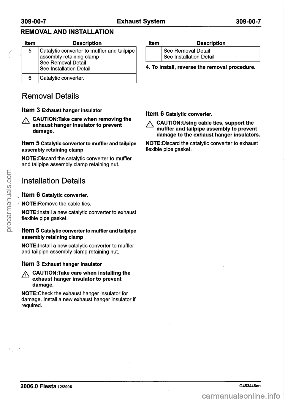
1 6 1 Catalytic converter. Description
Item Description
Removal Details
assembly
retaining clamp
Item 3 Exhaust hanger insulator ltem 6 catalvtic converter.
See
Removal Detail
See Installation Detail II CAUTI0N:Take care when removing the
exhaust hanger insulator to prevent A CAUTI0N:Using cable ties, support the
damage. muffler
and tailpipe assembly to prevent
damage to the exhaust hanger insulators.
See Removal
Detail
See Installation Detail
4. To install, reverse the removal procedure.
Item 5 Catalytic converter to muffler and tailpipe N0TE:Discard the catalytic converter to exhaust
assembly retaining clamp flexible pipe gasket.
N0TE:Discard the
catalytic converter to muffler
and tailpipe assembly clamp retaining nut.
Installation Details
, ltem 6 Catalytic converter.
' N0TE:Remove the cable ties.
N0TE:lnstall a new catalytic converter to exhaust
flexible pipe gasket.
Item 5 Catalytic converter to muffler and tailpipe
assembly retaining clamp
N0TE:lnstall a new catalytic converter to muffler
and tailpipe assembly clamp retaining nut.
Item 3 Exhaust hanger insulator
A CAUTI0N:Take care when installing the
exhaust hanger insulator to prevent
damage.
N0TE:Check the exhaust hanger insulator for
damage. Install a new exhaust hanger insulator if
required.
2006.0 Fiesta 1212006 G453448en
procarmanuals.com
Page 1184 of 1226
309=00=8 Exhaust System 309m00m8
REMOVAL AND INSTALLATION
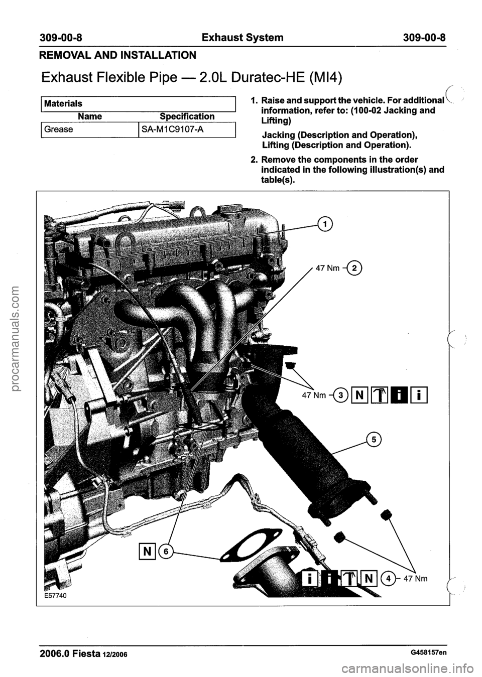
Exhaust Flexible Pipe - 2.OL Duratec-HE (M14)
Materials 1. Raise and support the vehicle. For additional \.. ;
information, refer to: (I 00-02 Jacking and
Name Specification
I 1 Liftinn)
Lifting (Description and Operation).
Grease I SA-M 1 C9 1 07-A
2. Remove the components in the order
indicated in the following
illustration(s) and
table(s).
-I
2006.0 Fiesta 1212006 G458157en
Jacking (Description and Operation),
procarmanuals.com
Page 1185 of 1226
309-00-9 Exhaust System 309-00-9
REMOVAL AND INSTALLATION
Itern Description Item Descri~tion
Heated oxygen sensor (H02S) electrical
connector See
Removal Detail
See lnstallation Detail
3. To install, reverse the removal procedure.
3
A CAUTI0N:Never use jointing compound
Exhaust flexible pipe to muffler and tailpipe forward of the catalytic converter.
assembly retaining nuts Exhaust
flexible pipe to exhaust manifold
retaining nuts
See Removal Detail
Removal Details
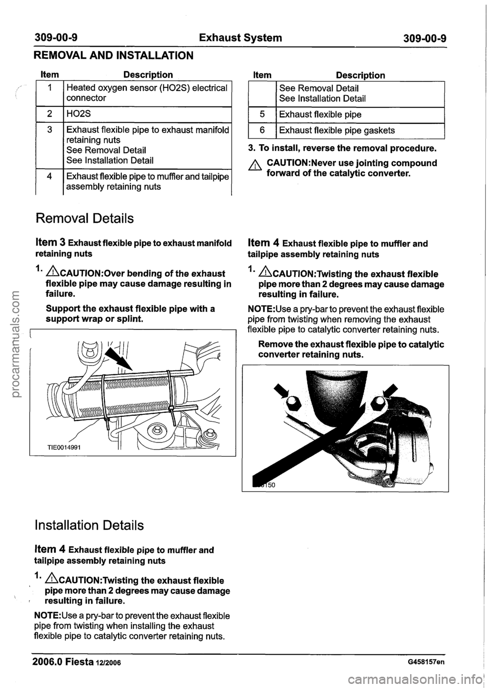
Item 3 Exhaust flexible pipe to exhaust manifold Ifem 4 Exhaust flexible pipe to muffler and
retaining nuts tailpipe assembly retaining nuts
Im &AUTION:O~~~ bending of the exhaust Im &Au~l~N:Twistin~ the exhaust flexible
flexible pipe may cause damage resulting in pipe more than
2 degrees may cause damage
failure. resulting in failure.
Support the exhaust flexible pipe with a
N0TE:Use a pry-bar to prevent the exhaust flexible
support wrap or splint. pipe from twisting when removing the exhaust
flexible pipe to catalytic converter retaining nuts.
Remove the exhaust flexible pipe to catalytic
converter retaining nuts.
Installation Details
Item 4 Exhaust flexible pipe to muffler and
tailpipe assembly retaining nuts
A~AuT10~:Twistin~ the exhaust flexible
pipe more than
2 degrees may cause damage
' resulting in failure.
N0TE:Use a pry-bar to prevent the exhaust flexible
pipe from twisting when installing the exhaust
flexible pipe to catalytic converter retaining nuts.
2006.0 Fiesta 1212006 G458157en
procarmanuals.com
Page 1186 of 1226
309-00-1 0 Exhaust System 309-00-1 0
REMOVAL AND INSTALLATION
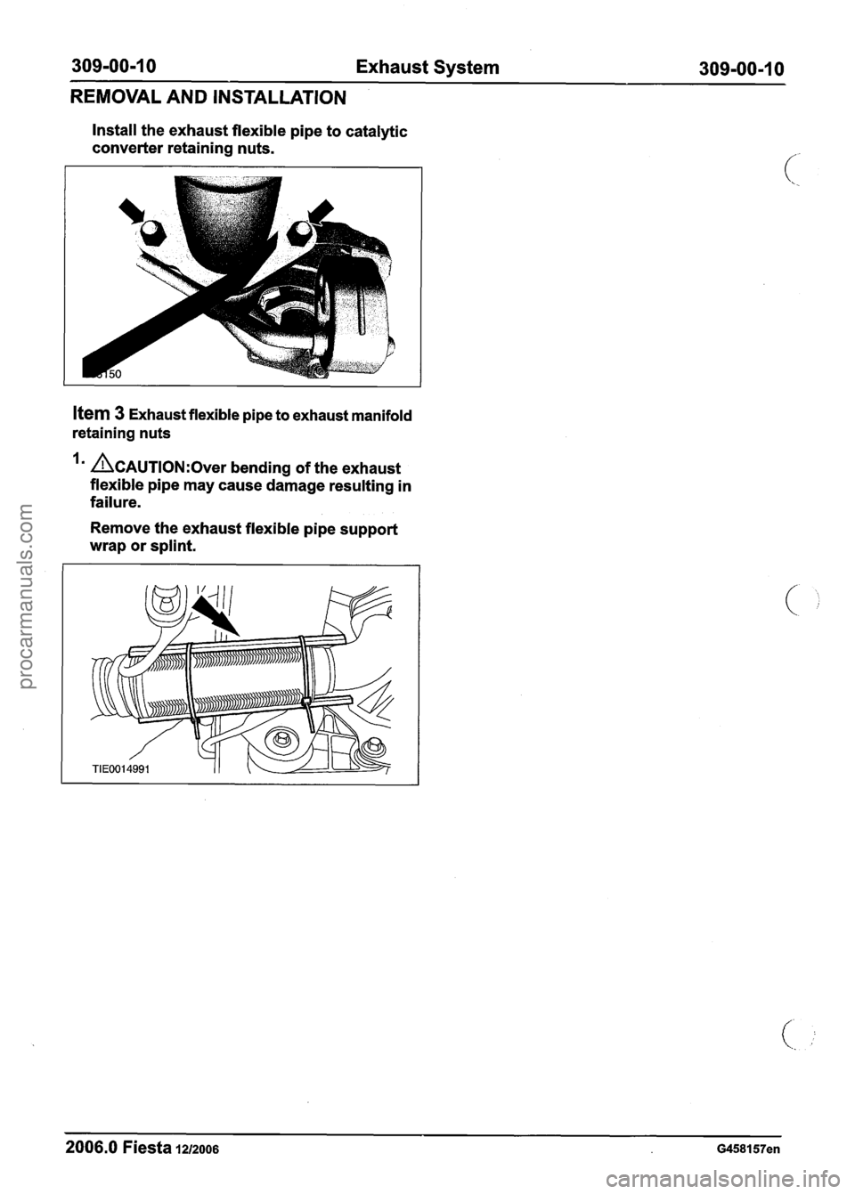
Install the exhaust flexible pipe to catalytic
converter retaining nuts.
Item 3 Exhaust flexible pipe to exhaust manifold
retaining nuts
Im CAUTION:^^^^ bending of the exhaust
flexible pipe may cause damage resulting in
failure.
Remove the exhaust
flexible pipe support
wrap or splint.
2006.0 Fiesta 1212006 G458157en
procarmanuals.com
Page 1187 of 1226
31 0-00-1 Fuel System - General Information 31 0-OO=l
SECTION 31 0-00 Fuel System - General lnformation
VEHICLE APPLICATION:2006.0 Fiesta
CONTENTS PAGE
DIAGNOSIS AND TESTING
Fuel System - 1.3L Duratec-8V (Rocam)ll.25L Duratec-I 6V (Sigma)/2.0L Duratec-HE
(M14)/1.4L Duratec-1 6V (Sigma)/l .6L
Duratec-1 6V (Sigma) ............................................ 3 1 0-00-2
........................................................................\
......................... Inspection and Verification. 3 1
0-00-2
GENERAL PROCEDURES
Fuel System Pressure Release .................................................................... (23 420 0) 3 1 0-00-3
Fuel Tank Draining
........................................................................\
.................. (23 551 0) 3 1 0-00-4
Quick Release Coupling
........................................................................\
............................. 3 1 0-00-5
................................................... Fuel System Pressure Check - 2.OL Duratec-HE (M14) 31 0-00-1 0
procarmanuals.com
Page 1188 of 1226
31 0-00-2 Fuel System - General Information 31 0-00-2
DIAGNOSIS AND TESTING
Fuel System - 1.3L Duratec-8V (Rocam)/l.25L Duratec-1 6V
(Sigma)/2.0L Duratec-HE (M14)/1.4L Duratec-I 6V
(Sigma)/l.GL Duratec-1 6V (Sigma)
lnspection and Verification
1. Verify the customer concern.
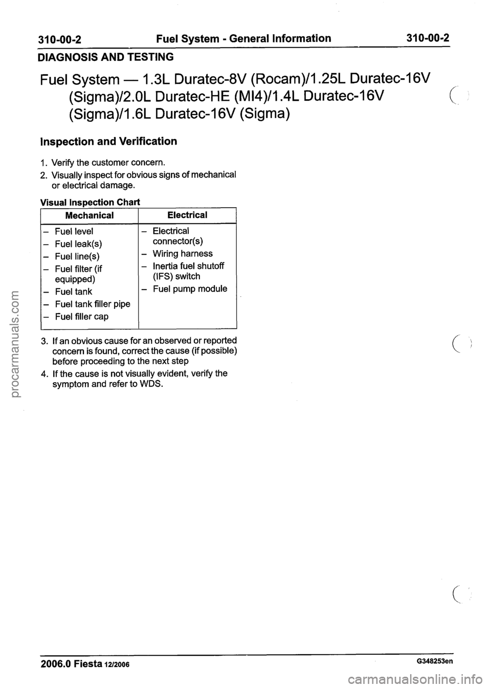
2. Visually inspect for obvious signs of mechanical
or electrical damage.
- Fuel level
- Fuel leak(s)
- Fuel line(s)
- Fuel filter (if
equipped)
- Fuel tank
- Fuel tank filler pipe
- Fuel filler cap
Visual lnspection Chart
- Electrical
connector(s)
- Wiring harness
- Inertia fuel shutoff
(IFS) switch
- Fuel pump module
I Mechanical
3. If an obvious cause for an observed or reported
concern is found, correct the cause (if possible)
before proceeding to the next step
4. If the cause is not visually evident, verify the
symptom and refer to WDS.
Electrical
-
2006.0 Fiesta 1212006 G348253en
procarmanuals.com
Page 1189 of 1226
31 0-00-3 Fuel System - General Information 31 0-00-3
GENERAL PROCEDURES
/'
Fuel System Pressure Release(23 420 0)
i
Release
I. WARNINGS:
ADO not smoke or carry lighted tobacco or
open flame of any type when working on or
near any fuel related components. Highly
flammable vapors are always present and
may ignite. Failure to follow these
instructions may result in personal injury.
A~he fuel system remains pressurized for
a long time after the ignition is switched off.
The fuel pressure must be released before
attempting any repairs. Failure to follow this
instruction may result in personal injury.
Remove the fuel pump fuse.
2. Start the engine and allow to idle until the
engine stalls.
3. Crank the engine for approximately five
seconds to make sure the fuel injection
supply manifold pressure has been released.
,1 4. Install the fuel pump fuse.
2006.0 Fiesta 1212006 GI 81 91 en
procarmanuals.com
Page 1190 of 1226
31 0-00-4 Fuel System - General Information 31 0-00-4
GENERAL PROCEDURES
Fuel Tank Draining(23 551 0)
General Eaui~ment
I Fuel tank draining equipment I
Draining
WARNINGS:
A Do not smoke or carry lighted tobacco or
open flame of any type when working on
or near any fuel related components.
Highly flammable vapors are always
present and may ignite. Failure to follow
these instructions may result in personal
injury.
A The fuel system remains pressurized for a
long time after the ignition is switched off.
The fuel pressure must be relieved before
attempting any repairs. Failure to follow
these instructions may result in personal
injury.
I. Disconnect the battery ground cable. For
additional information, refer to
Section
414-01 [Battery, Mounting and
Cables].
2. Remove the fuel tank filler cap.
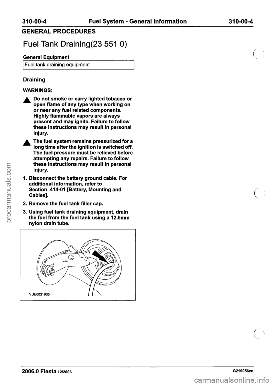
3. Using fuel tank draining equipment, drain
the fuel from the fuel tank using a
12.5mm
nylon drain tube.
2006.0 Fiesta 1212006 G210056en
procarmanuals.com