torque FORD FIESTA 2007 Workshop Manual
[x] Cancel search | Manufacturer: FORD, Model Year: 2007, Model line: FIESTA, Model: FORD FIESTA 2007Pages: 1226, PDF Size: 61.26 MB
Page 17 of 1226
100-00-1 General Information 100-00-1
. SECTION 100-00 General lnformation
VEHICLE APPLICATION:2006.0 Fiesta
CONTENTS
DESCRIPTION AND OPERATION
About This Manual
........................................................................\
......................................
........................................................................\
................................................. Introduction
Special Tools
........................................................................\
..............................................
Important Safety Instructions ........................................................................\
......................
Warnings. Cautions and Notes in This Manual ..................................................................
How to Use This Manual ........................................................................\
............................
Special Tools and Torque Figures ........................................................................\
..............
Health and Safety Precautions ........................................................................\
...................
........................................................................\
................................................. Introduction
........................................................................\
........................................ Acids and Alkalis
Air Bags
........................................................................\
......................................................
Air Conditioning Refrigerant ........................................................................\
.......................
........................................................................\
............................... Adhesives and Sealers
........................................................................\
................................................... Antifreeze
........................................................................\
..................................................... Asbestos
Battery Acids
........................................................................\
..............................................
Brake and Clutch Linings and Pads ........................................................................\
...........
Brake Fluids (Polyalkylene Glycols) ........................................................................\
...........
........................................................................\
....................................................... Brazing
Chemical Materials
........................................................................\
.....................................
................................................................... Chlorofluorocarbons (CFC) ... ..........................
Clutch Fluids ........................................................................\
...............................................
Clutch Linings and Pads ........................................................................\
.............................
Corrosion Protection Materials ........................................................................\
...................
........................................................................\
........................................................ Cutting
........................................................................\
.................................................... Dewaxing
........................................................................\
.......................................................... Dusts
Electric Shock
........................................................................\
.............................................
Engine Oils ........................................................................\
.................................................
Exhaust Fumes ........................................................................\
...........................................
........................................................................\
........................................... Fibre Insulation
Fire
........................................................................\
.............................................................
First Aid ........................................................................\
......................................................
........................................................................\
.......................................... Fluoroelastomer
Foams
. Polyurethane ........................................................................\
................................
........................................................................\
.......................................................... Freon
........................................................................\
........................................................... Fuels
........................................................................\
.............................................. Gas Cylinders
........................................................................\
......................................................... Gases
Gaskets (Fluoroelastomer)
........................................................................\
.........................
General Workshop Tools and Equipment ........................................................................\
...
High Pressure Air. Lubrication and Oil Test Equipment ......................................................
........................................................................\
.......................................................... Halon
........................................................................\
............................................. Legal Aspects
PAGE
procarmanuals.com
Page 19 of 1226
100-00-3 General Information 100-00-3
DESCRIPTION AND OPERATION
About This Manual
-- . Introduction
This manual has been written in a format that is
designed to meet the needs of technicians
worldwide. The objective is to use common formats
and include similar content in each manual.
This manual provides general descriptions for accomplishing diagnosis and testing, service and
repair work with tested, effective techniques.
Following them will help assure reliability.
Special Tools
The special tool(s) table provided at the beginning
of each procedure shows all special tools required
to carry out a repair. Where possible, illustrations
are provided to assist in identifying the special tool
required.
Important Safety Instructions
Appropriate service methods and correct repair
--.! procedures are essential for the safe, reliable
operation of all motor vehicles as well as the
personal safety of the individual carrying out the
work.
This manual cannot possibly anticipate all such
variations and provide advice or cautions as to
each. Anyone who departs from the instructions
provided in this manual must first establish that he
compromises neither his personal safety nor the
vehicle integrity by his choice of methods, tools or
components.
Warnings, Cautions and Notes in This
Manual
A WARN1NG:Warnings are used to indicate
that failure to follow a procedure correctly
may result in personal injury.
A warning, caution or note is placed at the
beginning of a series of steps if it applies to multiple
steps. If the warning, caution or note only applies
to one step, it is placed at the beginning of the
specific step (after the step number).
How to Use This Manual
This manual covers diagnosis and testing, service
and repair procedures.
This manual is structured into groups and sections,
with specific system sections collected together
under their relevant group.
A group covers a specific portion of the vehicle.
The manual is divided into five groups, General
Information, Chassis, Powertrain, Electrical and
Body and Paint. The number of the group is the
first number of a section number.
Pages at the start of the manual list all sections
available. Each section has a contents list detailing
Specifications, Description and Operation,
Diagnosis and Testing, In Vehicle Repairs,
Disassembly and Assembly, Removal and
Installation.
If components need to be removed or
disassembled in sequence, the sequence will be
identified numerically in a graphic and the
corresponding text will be numbered accordingly.
All left and right-hand references to the vehicle are
taken from a position sitting in the driver seat
looking forward.
All left and right-hand references to the engine are
taken from a position at the flywheel looking
towards the front camshaft pulley.
Where appropriate, instructions will be given for
the use of the diagnostic tool.
Overview Procedures
Overview procedures contain an exploded view
A CAUTI0N:Cautions are used to indicate illustration(s). The numbered sequence within the
that failure to follow a procedure correctly illustration(s) indicate the order to be followed when
may result in damage to the vehicle or removingldisassem bling or when
equipment being used. installinglassembling a component. Additional
information,
symbol(s) or a torque figure, may also
, , N0TE:Notes are used to provide additional
be shown alonaside the com~onent.
essential information required to carry out a
complete and satisfactory repair. There are
ten symbols used to give additional
information when
removina/disassemblincr or when V AS YOU read through this manual, YOU will come /"itallinglassembling a c&ponent.
across WARNINGS, CAUTIONS and NOTES.
2006.0 Fiesta 1212006 GI 7371 en
procarmanuals.com
Page 21 of 1226
100-00-5 General Information 100-00-5
DESCRIPTION AND OPERATION
Component Tests
' A component test is used when a component is
tested in multiple pinpoint tests, or if a procedure
is too complicated to be formatted within a single
page of the pinpoint test.
Graphics
Test graphics show the measurement or test to be
performed in a test step.
A representative tester graphic is used for
voltmeters and ohmmeters.
If multiple measurements are made in a single
graphic, the test leads are drawn with a solid line
until the test lead splits to indicate the multiple
measurements, at which point dashed lines are
used.
Breakout box-type testers are represented by a
double circle test pin. Test pins are labeled with
the pin number.
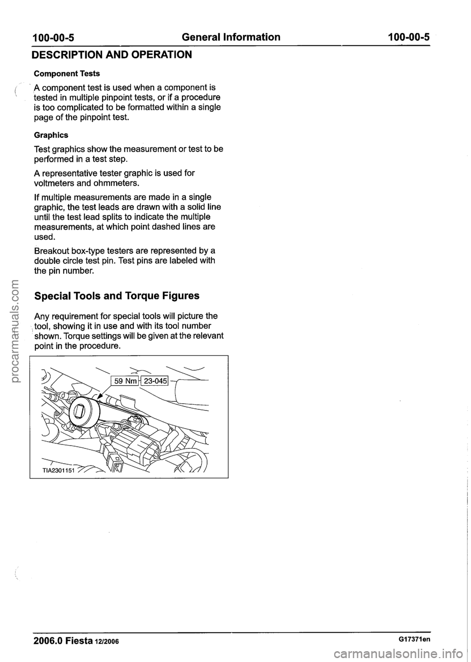
Special Tools and Torque Figures
Any requirement for special tools will picture the
tool, showing it in use and with its tool number
( ' shown. Torque settings will be given at the relevant
point in the procedure.
2006.0 Fiesta 1212006 GI 7371 en
procarmanuals.com
Page 37 of 1226
I 00-00-21 General Information 1 00-00-21
DESCRIPTION AND OPERATION
Always disconnect the jumper cables in the reverse
order to the connecting sequence and do not short
i the ends of the cables.
Do not rely on the generator to restore a
discharged battery. For a generator to recharge a
battery, it would take in excess of eight hours
continuous driving with no additional loads placed
on the battery.
Component Cleaning
To prevent the ingress of dirt, accumulations of
loose dirt and greasy deposits should be removed
before disconnecting or dismantling components
or assemblies.
Components should be thoroughly cleaned before inspection prior to reassembly.
Cleaning Methods:
- Dry cleaning.
- Removal of loose dirt with soft or cable brushes.
- Scraping dirt off with a piece of metal or wood.
( ,- Wiping off with a rag.
A WARN1NG:Wear eye protection when
cleaning vehicle components with
compressed air, a steam cleaner or a
power washer. Failure to follow this
instruction may result in personal injury.
CAUTIONS:
A Compressed air is sometimes 'wet' so use
with caution, especially on hydraulic
systems.
A To prevent damage to the electrical
connectors in the engine compartment, do
not use a steam cleaner or a power washer
to clean the engine compartment.
- Blowing dirt off with compressed air.
- Removal of dry dust using vacuum equipment.
This method must always be used to remove
friction lining material dust (asbestos particles).
- Steam cleaning.
A WARN1NG:Most solvents require careful
handling and some are harmful. Refer to
Health and Safety Precautions and to the
manufacturers literature for the relevant
safety precautions. Failure to follow these
instructions may result in personal injury.
Various solvents are available which are suitable
for component cleaning. Some components, such
as brake hydraulic parts and electrical assemblies
should be cleaned only with recommended solvents
- refer to Solvents, Sealers and Adhesives or to
the section of the manual relevant to the
component.
Calibration of Essential Measuring
Equipment
A WARNING:Equipment, which requires
regular calibration, must be calibrated in
accordance with the manufacturers
instructions. Failure to follow this
instruction may result in personal injury
or damage to components.
It is of fundamental importance that certain
essential equipment, for example torque wrenches,
multimeters, exhaust gas analyzers or rolling roads,
are regularly calibrated in accordance with the
manufacturers instructions.
2006.0 Fiesta 1212006 GI 7373en
procarmanuals.com
Page 62 of 1226
100-04-6 Noise, Vibration and Harshness 100-04-6
DIAGNOSIS AND TESTING
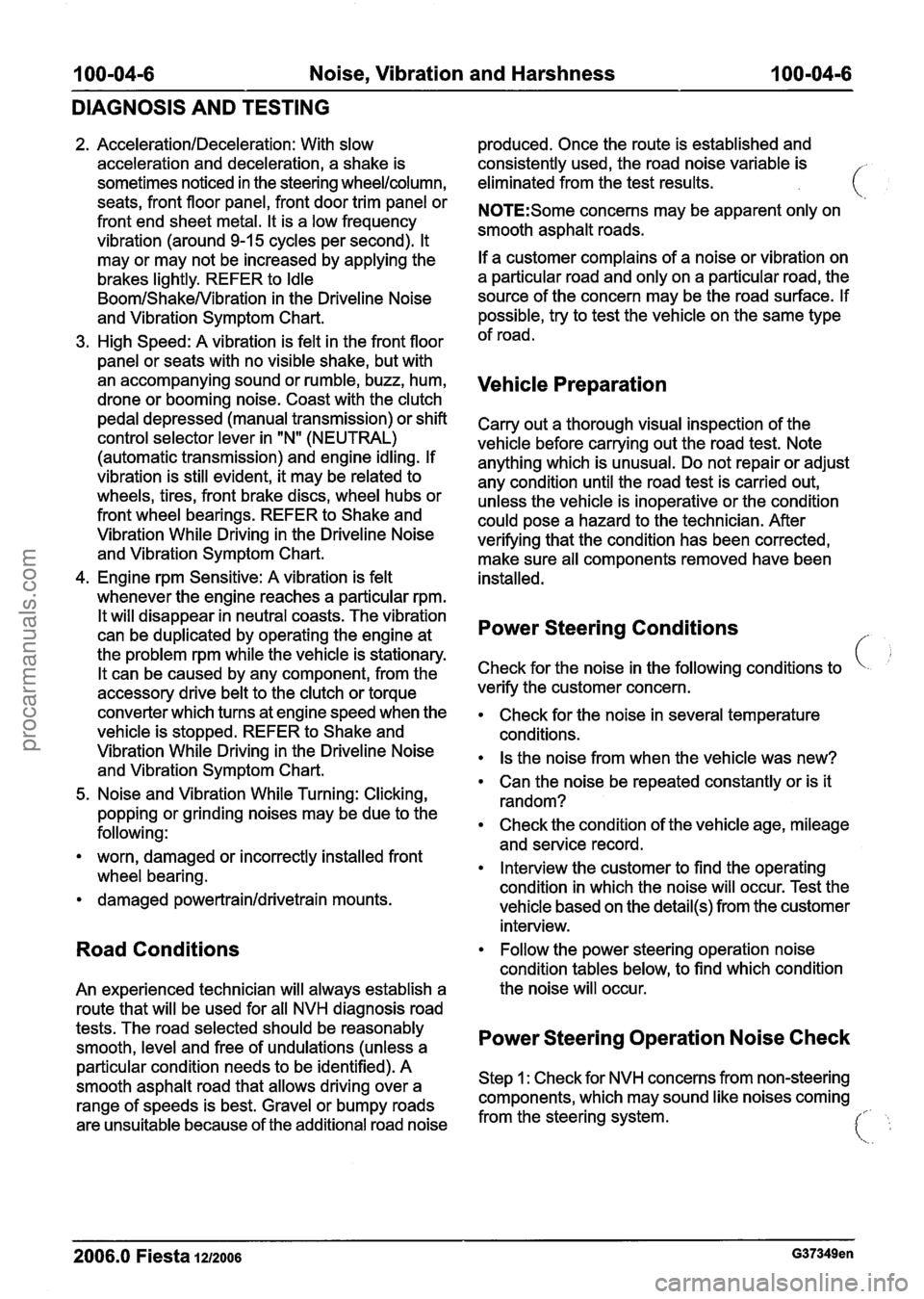
2. AccelerationIDeceleration: With slow
acceleration and deceleration, a shake is
sometimes noticed in the steering
wheellcolumn,
seats, front floor panel, front door trim panel or
front end sheet metal. It is a low frequency
vibration (around
9-1 5 cycles per second). It
may or may not be increased by applying the
brakes lightly. REFER to
Idle
BoomIShakeNibration in the Driveline Noise
and Vibration Symptom Chart.
High Speed: A vibration is felt in the front floor
panel or seats with no visible shake, but with
an accompanying sound or rumble, buzz, hum,
drone or booming noise. Coast with the clutch
pedal depressed (manual transmission) or shift
control selector lever in "N" (NEUTRAL)
(automatic transmission) and engine idling. If
vibration is still evident, it may be related to
wheels, tires, front brake discs, wheel hubs or
front wheel bearings. REFER to Shake and
Vibration While Driving in the Driveline Noise
and Vibration Symptom Chart.
4. Engine rpm Sensitive: A vibration is felt
whenever the engine reaches a particular rpm.
It will disappear in neutral coasts. The vibration
can be duplicated by operating the engine at
the problem rpm while the vehicle is stationary.
It can be caused by any component, from the
accessory drive belt to the clutch or torque
converter which turns at engine speed when the
vehicle is stopped. REFER to Shake and
Vibration While Driving in the Driveline Noise
and Vibration Symptom Chart.
5. Noise and Vibration While Turning: Clicking,
popping or grinding noises may be due to the
following:
worn, damaged or incorrectly installed front
wheel bearing.
damaged
powertrainldrivetrain mounts.
Road Conditions
An experienced technician will always establish a
route that will be used for all NVH diagnosis road
tests. The road selected should be reasonably
smooth, level and free of undulations (unless a
particular condition needs to be identified). A
smooth asphalt road that allows driving over a
range of speeds is best. Gravel or bumpy roads
are unsuitable because of the additional road noise produced.
Once the route is established and
consistently used, the road noise variable is
eliminated from the test results.
N0TE:Some concerns may be apparent only on
smooth asphalt roads.
If a customer complains of a noise or vibration on
a particular road and only on a particular road, the
source of the concern may be the road surface. If
possible, try to test the vehicle on the same type
of road.
Vehicle Preparation
Carry out a thorough visual inspection of the
vehicle before carrying out the road test. Note
anything which is unusual. Do not repair or adjust
any condition until the road test is carried out,
unless the vehicle is inoperative or the condition
could pose a hazard to the technician. After
verifying that the condition has been corrected,
make sure all components removed have been
installed.
Power Steering Conditions
c !
Check for the noise in the following conditions to
verify the customer concern.
Check for the noise in several temperature
conditions.
Is the noise from when the vehicle was new?
Can the noise be repeated constantly or is it
random?
Check the condition of the vehicle age, mileage
and service record.
Interview the customer to find the operating
condition in which the noise will occur. Test the
vehicle based on the
detail(s) from the customer
interview.
Follow the power steering operation noise
condition tables below, to find which condition
the noise will occur.
Power Steering Operation Noise Check
Step 1 : Check for NVH concerns from non-steering
components, which may sound like noises coming
from the steering system.
I:. ':
2006.0 Fiesta 121zoo6 G37349en
procarmanuals.com
Page 100 of 1226
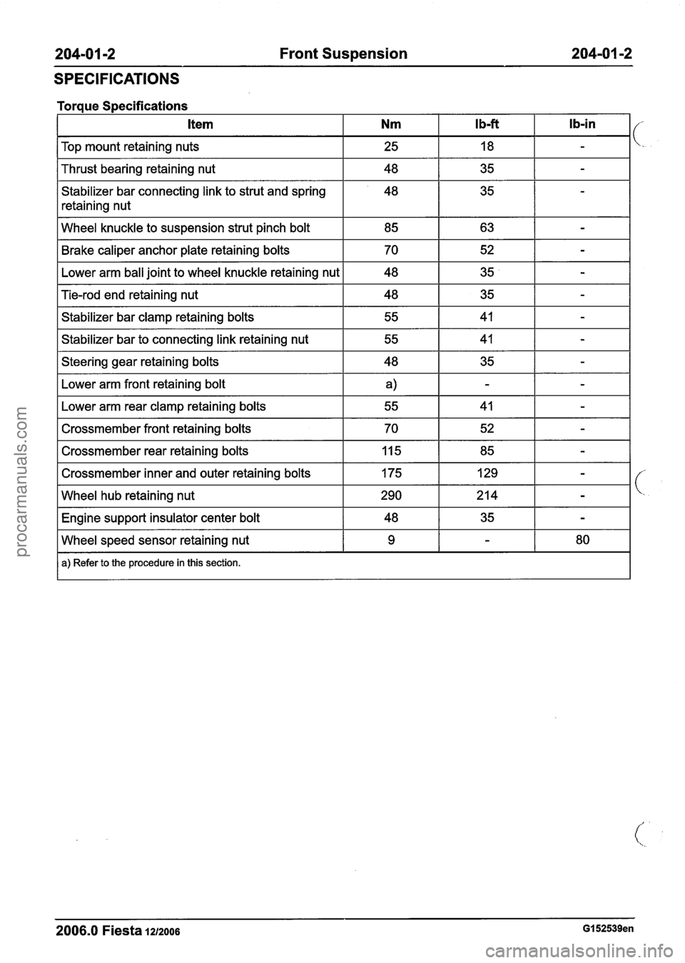
204-01 -2 Front Suspension 204-01 -2
SPECIFICATIONS
I Top mount retaining nuts I 25 I 18 I - I
Torque Specifications
I Thrust bearing retaining nut I 48 I 35 I - I
Stabilizer bar connecting link to strut and spring
retaining nut Ib-in
I Wheel
knuckle to suspension strut pinch bolt I 85 I 63 I - I
Ib-ft Item Nm
Brake caliper anchor plate retaining bolts
Lower arm ball joint to wheel knuckle retaining nut
I Steering gear retaining bolts I 48 I 35 I - I
Tie-rod end retaining nut
Stabilizer bar clamp retaining bolts
Stabilizer bar to connecting link retaining nut
Fb.wer arm front retaining bolt I
70
48
I Lower arm rear clamp retaining bolts I 55 I 41 I - I
48
55
55
I Crossmember front retaining bolts I 70 I 52 I - I
52
35
I Crossmember rear retaining bolts 1 Iq5 1 85 I - I
-
-
35
41
41
I Crossmember inner and outer retaining bolts 1 175 1 129 1 - I
-
-
-
I Wheel hub retaining nut 1290 1214 1 - I
I Engine support insulator center bolt I 48 I 35 I - I
2006.0 Fiesta 1212006 GI 52539en
Wheel speed sensor retaining nut
a) Refer to the procedure in this section.
9 - 80
procarmanuals.com
Page 124 of 1226
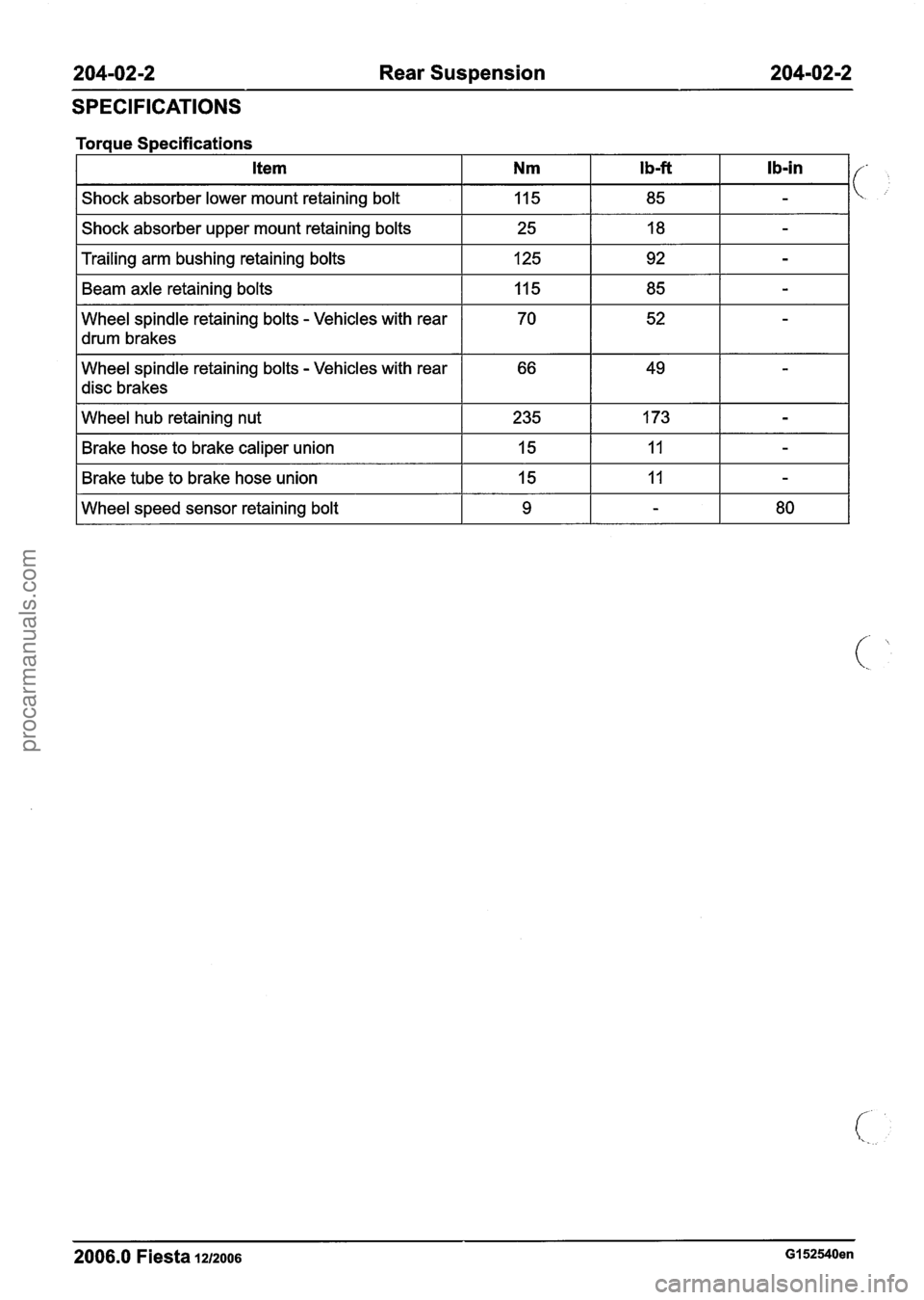
204-02-2 Rear Suspension 204-02-2
SPECIFICATIONS
Torque Specifications
I Shock absorber upper mount retaining bolts I 25 I 18 I - I
Item
Shock absorber lower mount retaining bolt
I Trailing arm bushing retaining bolts I 125 1 92 I - I
Nm
115
I drum brakes I I I I
Beam axle retaining bolts
Wheel spindle retaining bolts
- Vehicles with rear
Wheel spindle retaining bolts
- Vehicles with rear
disc brakes
Ib-ft
85
I Wheel hub retaining nut 1 235 1 173 1 - I
I b-in
-
115
70
I Brake hose to brake caliper union I 15 I 11 I - I
I Brake tube to brake hose union I 15 I 11 I - I
85
52
I Wheel speed sensor retaining bolt I 9 I - I 80 I
-
-
2006.0 Fiesta 1212006 GI 52540en
procarmanuals.com
Page 147 of 1226
204-04-3 Wheels and Tires 204-04-3
DIAGNOSIS AND TESTING
Wheels and Tires
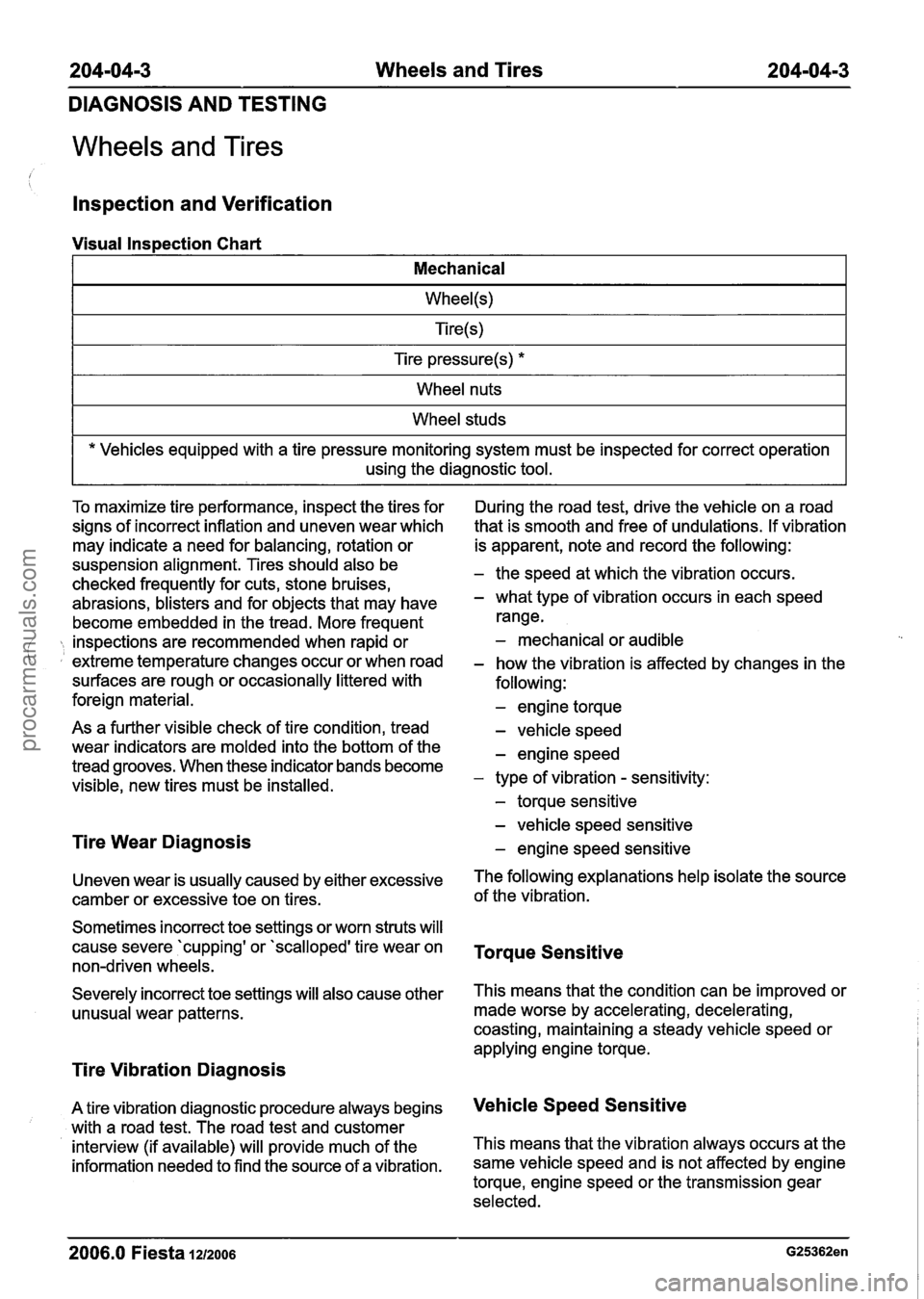
lnspection and Verification
Visual Inspection Chart
I Mechanical I
I Tire pressure(s) * I
I Wheel nuts I
I Wheel studs I
* Vehicles equipped with a tire pressure monitoring system must be inspected for correct operation
using the diagnostic tool.
To maximize tire performance, inspect the tires for
signs of incorrect inflation and uneven wear which
may indicate a need for balancing, rotation or
suspension alignment. Tires should also be
checked frequently for cuts, stone bruises,
abrasions, blisters and for objects that may have
become embedded in the tread. More frequent
inspections are recommended when rapid or ( extreme temperature changes occur or when road
surfaces are rough or occasionally littered with
foreign material.
As a further visible check of tire condition, tread
wear indicators are molded into the bottom of the
tread grooves. When these indicator bands become
visible, new tires must be installed.
Tire Wear Diagnosis
Uneven wear is usually caused by either excessive
camber or excessive toe on tires.
Sometimes incorrect toe settings or worn struts will
cause severe 'cupping' or 'scalloped' tire wear on
non-driven wheels.
Severely incorrect toe settings will also cause other unusual wear patterns.
Tire Vibration Diagnosis
A tire vibration diagnostic procedure always begins
with a road test. The road test and customer
interview (if available) will provide much of the
information needed to find the source of a vibration. During
the road test, drive the vehicle on a road
that is smooth and free of undulations. If vibration
is apparent, note and record the following:
- the speed at which the vibration occurs.
- what type of vibration occurs in each speed
range.
- mechanical or audible
- how the vibration is affected by changes in the
following:
- engine torque
- vehicle speed
- engine speed
- type of vibration - sensitivity:
- torque sensitive
- vehicle speed sensitive
- engine speed sensitive
The following explanations help isolate the source
of the vibration.
Torque Sensitive
This means that the condition can be improved or
made worse by accelerating, decelerating,
coasting, maintaining a steady vehicle speed or
applying engine torque.
Vehicle Speed Sensitive
This means that the vibration always occurs at the
same vehicle speed and is not affected by engine
torque, engine speed or the transmission gear
selected.
2006.0 Fiesta 1212006
procarmanuals.com
Page 202 of 1226
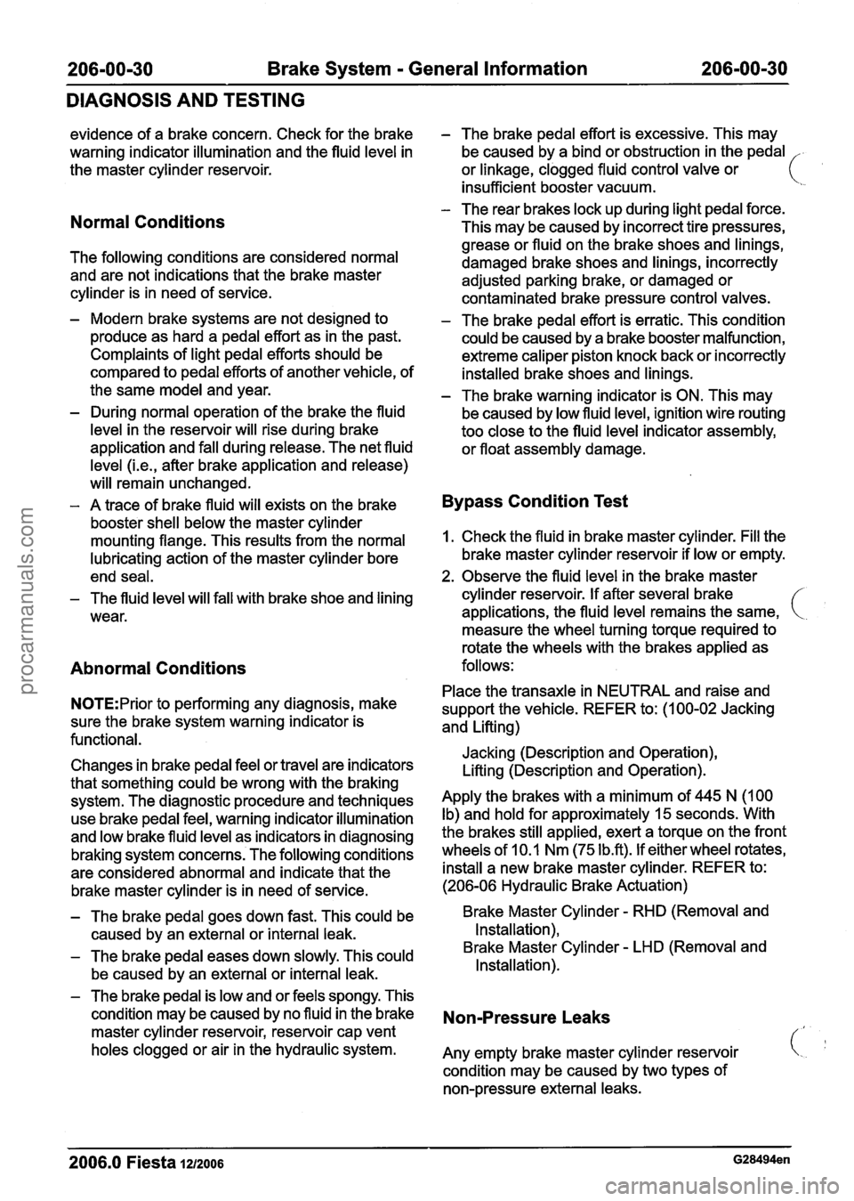
Brake System - General Information
DIAGNOSIS AND TESTING
evidence of a brake concern. Check for the brake
warning indicator illumination and the fluid level in
the master cylinder reservoir.
Normal Conditions
The following conditions are considered normal
and are not indications that the brake master
cylinder is in need of service.
- Modern brake systems are not designed to
produce as hard a pedal effort as in the past.
Complaints of light pedal efforts should be
compared to pedal efforts of another vehicle, of
the same model and year.
- During normal operation of the brake the fluid
level in the reservoir will rise during brake
application and fall during release. The net fluid
level
(i.e., after brake application and release)
will remain unchanged.
- A trace of brake fluid will exists on the brake
booster shell below the master cylinder
mounting flange. This results from the normal
lubricating action of the master cylinder bore
end seal.
- The fluid level will fall with brake shoe and lining
wear.
Abnormal Conditions
N0TE:Prior to performing any diagnosis, make
sure the brake system warning indicator is
functional.
Changes in brake pedal feel or travel are indicators
that something could be wrong with the braking system. The diagnostic procedure and techniques
use brake pedal feel, warning indicator illumination
and low brake fluid level as indicators in diagnosing
braking system concerns. The following conditions
are considered abnormal and indicate that the
brake master cylinder is in need of service.
- The brake pedal effort is excessive. This may
be caused by a bind or obstruction in the pedal
.
or linkage, clogged fluid control valve or ( ' insufficient booster vacuum.
- The rear brakes lock up during light pedal force.
This may be caused by incorrect tire pressures,
grease or fluid on the brake shoes and linings,
damaged brake shoes and linings, incorrectly
adjusted parking brake, or damaged or
contaminated brake pressure control valves.
- The brake pedal effort is erratic. This condition
could be caused by a brake booster malfunction,
extreme caliper piston knock back or incorrectly
installed brake shoes and linings.
- The brake warning indicator is ON. This may
be caused by low fluid level, ignition wire routing
too close to the fluid level indicator assembly,
or float assembly damage.
Bypass Condition Test
1. Check the fluid in brake master cylinder. Fill the
brake master cylinder reservoir if low or empty.
2. Observe the fluid level in the brake master
cylinder reservoir. If after several brake
applications, the fluid level remains the same,
measure the wheel turning torque required to
rotate the wheels with the brakes applied as
follows:
Place the transaxle in NEUTRAL and raise and
support the vehicle. REFER to: (1 00-02 Jacking
and Lifting)
Jacking (Description and Operation),
Lifting (Description and Operation).
Apply the brakes with a minimum of 445 N (100
Ib) and hold for approximately 15 seconds. With
the brakes still applied, exert a torque on the front
wheels of 10.1 Nm (75
1b.R). If either wheel rotates,
install a new brake master cylinder. REFER to:
(206-06 Hydraulic Brake Actuation)
- The brake pedal goes down fast. This could be Brake Master Cylinder - RHD (Removal and
caused by an external or internal leak. Installation),
- The brake
pedal eases down slowly. This could Brake Master Cylinder - LHD
(Removal and
be caused by an external or internal leak. Installation).
- The
brake pedal is low and or feels spongy. This
condition may be caused by no fluid in the brake
Non-Pressure Leaks master cylinder reservoir, reservoir cap vent
holes clogged or air in the hydraulic system.
Any empty brake master cylinder reservoir
condition may be caused by two types of
non-pressure external leaks.
2006.0 Fiesta 1212006
procarmanuals.com
Page 218 of 1226
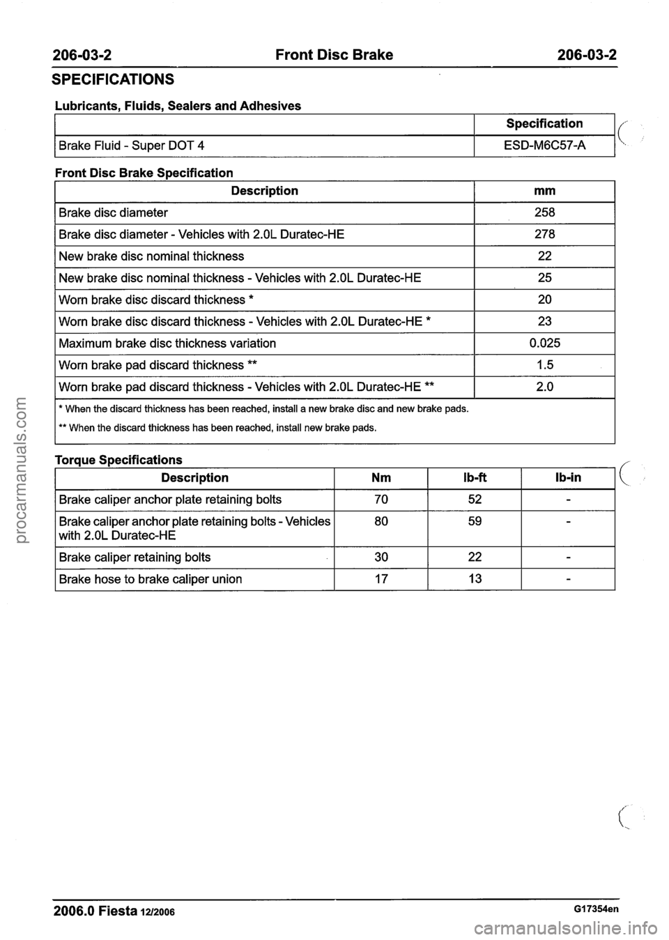
206-03-2 Front Disc Brake 206-03-2
SPECIFICATIONS
Lubricants, Fluids, Sealers and Adhesives
Specification
Brake Fluid - Super DOT 4 ESD-M6C57-A
Front Disc Brake Specification
I Brake disc diameter - Vehicles with 2.OL Duratec-HE I 278 I
Description
Brake disc diameter
I New brake disc nominal thickness I 22 I
mm
258
New brake disc nominal thickness
- Vehicles with 2.OL Duratec-HE
Worn brake disc discard thickness
*
I Worn brake pad discard thickness ** I 1.5 I
25
20
Worn brake disc discard thickness
- Vehicles with 2.OL Duratec-HE *
Maximum brake disc thickness variation
I Worn brake pad discard thickness - Vehicles with 2.OL Duratec-HE ** I 2.0 I
23
0.025
I * When the discard thickness has been reached, install a new brake disc and new brake pads.
I ** When the discard thickness has been reached, install new brake pads.
Torque Specifications
Description
Nm Ib-ft lb-in I(
I Brake caliper anchor plate retaining bolts I 70 I 52 I - I
Brake caliper anchor plate retaining bolts - Vehicles
L2.OLuratec-H E
I Brake caliper retaining bolts I 30 I 22 I - I
me hose to brake caliper union I 17 I 13 I - I
2006.0 Fiesta 1212006 GI 7354en
procarmanuals.com