310 FORD FIESTA 2007 Workshop Manual
[x] Cancel search | Manufacturer: FORD, Model Year: 2007, Model line: FIESTA, Model: FORD FIESTA 2007Pages: 1226, PDF Size: 61.26 MB
Page 12 of 1226

Exhaust System (I
Exhaust System ........................................................................\
..................................... 309-00
Fuel System
Fuel System
- General Information ........................................................................\
.... 310-00
Fuel Tank and Lines..
........................................................................\
............................ .310-01
Acceleration Controll.3L Duratec-8V (Rocam)ll.25L Duratec-1 6V (Sigma)ll.4L
Duratec-1 6V (Sigma)ll .6L Duratec-1 6V (Sigma) ....................................................... 310-02A
Acceleration
Control2.0L Duratec-HE (M14) .............................................................. 30-02B
0512005 2006.0 Fiesta
procarmanuals.com
Page 154 of 1226
205-04-2 Front Drive Halfshafts 205-04-2
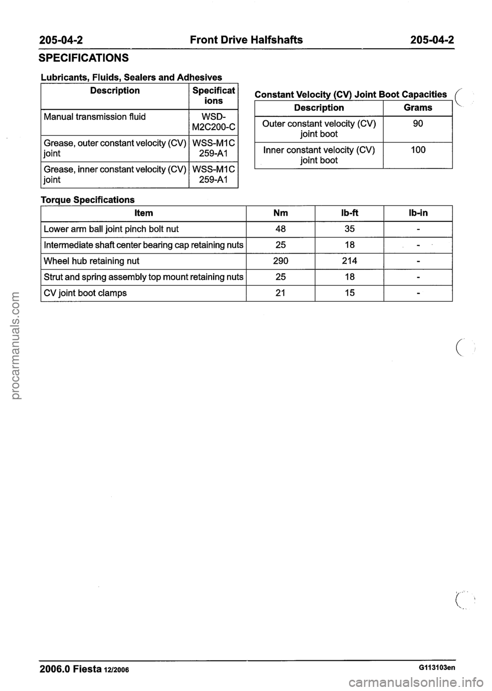
SPECIFICATIONS
Lubricants, Fluids, Sealers and Adhesives
Description
/ Specificat 1
ions
Manual transmission fluid
Grease, outer constant velocity (CV) WSS-MI C
joint
1 259-A1 1
Grease, inner constant velocity (CV) WSS-MI C
joint
1 259-A1 1
Toraue S~ecifications
Outer constant velocity (CV) joint boot
Constant Velocity (CV) Joint Boot Capacities
Inner constant velocity (CV)
joint boot
Description
I Lower arm ball joint pinch bolt nut I 48 I 35 I - I
Grams
I Intermediate shaft center bearing cap retaining nuts I 25 I 18 I - I
I Wheel hub retaining nut 1 290 1214 1 - I
I Strut and spring assembly top mount retaining nuts I 25 I 18 I - I
I CV joint boot clamps I 21 I 15 I - I
2006.0 Fiesta iu200s GII 3103en
procarmanuals.com
Page 158 of 1226
205-04-6 Front Drive Halfshafts 205-04-6
REMOVAL AND INSTALLATION
Front Halfshaft LH(14 320 0)
I I Installer, Halfshaft
(%. .
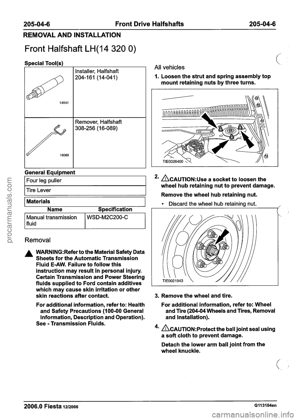
1 All vehicles
1. Loosen the strut and spring assembly top
mount retaining nuts by three turns.
General
Eaui~ment
I Four leg puller I
Tire Lever
Materials
Name Specification
Removal
Manual transmission
1 fluid
A WARNING:Refer to the Material Safety Data
Sheets for the Automatic Transmission
Fluid
E-AW. Failure to follow this
instruction may result in personal injury.
Certain Transmission and Power Steering
fluids supplied to Ford contain additives
which may cause skin irritation or other
skin reactions after contact.
WSD-M2C200-C
2' ACAUTION:~~~ a socket to loosen the
wheel hub retaining nut to prevent damage.
Remove the wheel hub retaining nut.
Discard the wheel hub retaining nut. ,'
3. Remove the wheel and tire.
For additional information, refer to: Health For
additional information, refer to: Wheel
and Safety Precautions
(1 00-00 General and
Tire (204-04 Wheels and Tires, Removal
Information, Description and Operation). and
Installation).
See
- Transmission Fluids.
4m Ac~u~10~:~rotect the ball joint seal using
a soft cloth to prevent damage.
Detach the lower arm ball joint from the
wheel knuckle.
2006.0 Fiesta IZIZOO~ G113104en
procarmanuals.com
Page 160 of 1226
205-0418 Front Drive Halfshafts 205-0418
REMOVAL AND INSTALLATION
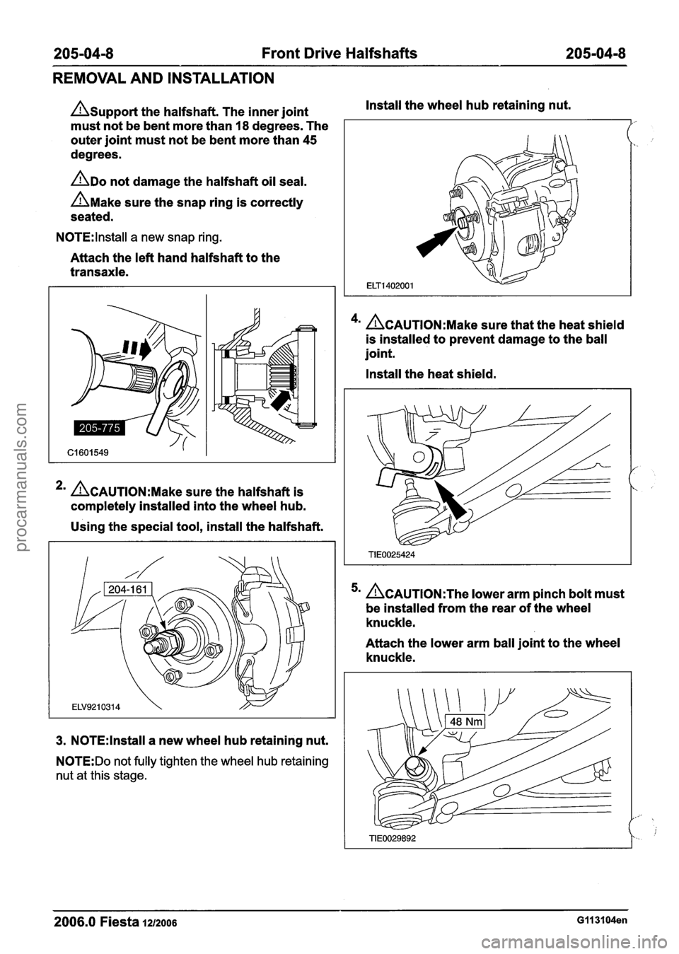
Asupport the halfshaft. The inner joint
must not be bent more than 18 degrees. The
outer joint must not be bent more than
45
degrees.
ADO not damage the halfshaft oil seal.
AMake sure the snap ring is correctly
seated.
N0TE:lnstall a new snap ring.
Attach the left hand halfshaft to the
transaxle.
*' ACAUTION:M~~~ sure the halfshaft is
completely installed into the wheel hub.
Using the special tool, install the halfshaft.
3. N0TE:lnstall a new wheel hub retaining nut.
N0TE:Do not fully tighten the wheel hub retaining
nut at this stage. Install
the wheel hub retaining nut.
4m ACAUTION:M~~~ sure that the heat shield
is installed to prevent damage to the ball
joint.
Install the heat shield.
~CAUTION:T~~ lower arm pinch bolt must
be installed from the rear of the wheel
knuckle.
Attach the lower arm ball joint to the wheel
knuckle.
2006.0 Fiesta 1212006 G113104en
procarmanuals.com
Page 164 of 1226
205-04-1 2 Front Drive Halfshafts 205-04-1 2
REMOVAL AND INSTALLATION
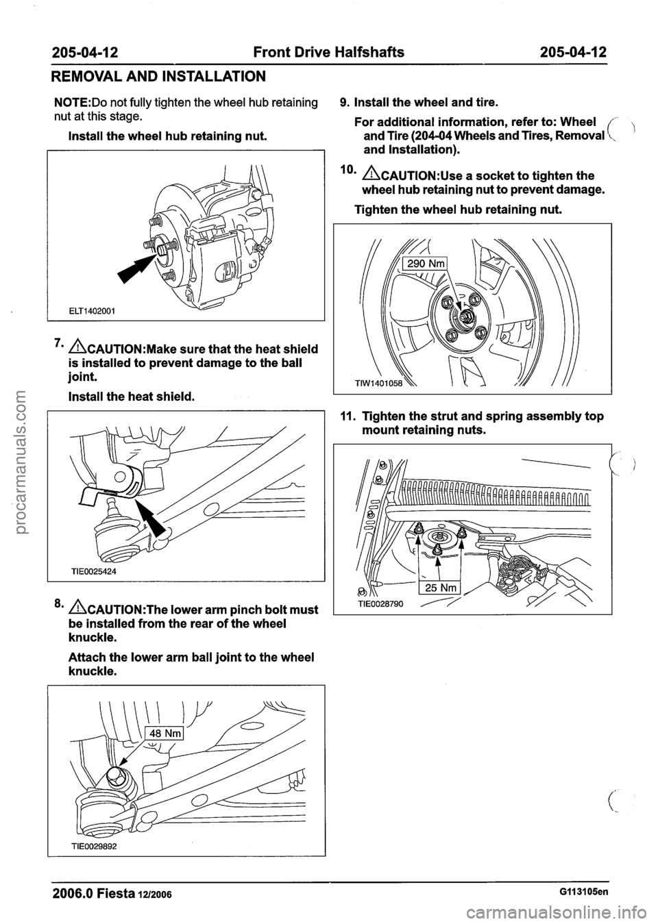
N0TE:Do not fully tighten the wheel hub retaining 9. Install the wheel and tire.
nut at this stage. For additional information, refer to: Wheel
Install the wheel hub retaining nut. and
Tire (204-04 Wheels and Tires, Removal
and Installation).
lorn &AUTION:U~~ a socket to tighten the
wheel hub retaining nut to prevent damage.
7m &AUTION:M~~~ sure that the heat shield
is installed to prevent damage to the ball
joint.
Install the heat shield.
*' &AUTION:T~~ lower arm pinch bolt must
be installed from the rear of the wheel
knuckle.
Attach the lower arm ball joint to the wheel
knuckle. Tighten
the wheel hub retaining nut.
11. Tighten the strut and spring assembly top
mount retaining nuts.
2006.0 Fiesta 1212006 GII 3105en
procarmanuals.com
Page 433 of 1226
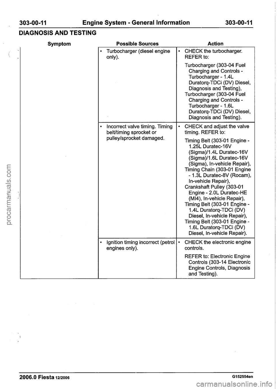
303-00-1 I Engine System - General Information 303-00-1 I
DIAGNOSIS AND TESTING
Symptom Possible
Sources Action --
Turbocharger (diesel engine
only).
CHECK the turbocharger.
REFER to:
Turbocharger (303-04
Fuel
Charging and Controls -
Turbocharger - 1.4L
Duratorq-TDCi (DV) Diesel,
Diagnosis and Testing),
Turbocharger (303-04
Fuel
Charging and Controls -
Turbocharger - 1.6L
Duratorq-TDCi (DV) Diesel,
Diagnosis and Testing).
Incorrect valve timing. Timing
beltltiming sprocket or
pulleylsprocket damaged. CHECK
and adjust the
valve
timing. REFER to:
Timing
Belt (303101 Engine -
I .25L Duratec-1 6V
(Sigma)ll.4L Duratec-1 6V
(Sigma)ll .6L Duratec-1 6V
(Sigma), In-vehicle Repair),
Timing Chain (303-01 Engine
- 1.3L Duratec-8V (Rocam),
In-vehicle Repair),
Crankshaft
Pulley (303-01
Engine
- 2.OL Duratec-HE
(M14), In-vehicle Repair),
Timing
Belt (303-01 Engine -
1.4L Duratorq-TDCi (DV)
Diesel, In-vehicle Repair),
Timing
Belt (303-01 Engine -
1.6L Duratorq-TDCi (DV)
Diesel, In-vehicle Repair).
Ignition timing incorrect (petrol
engines only).
CHECK the electronic engine
controls.
REFER to: Electronic Engine
Controls (303-1 4 Electronic
Engine Controls, Diagnosis
and Testing).
2006.0 Fiesta 1212006 GI 52554en
procarmanuals.com
Page 500 of 1226
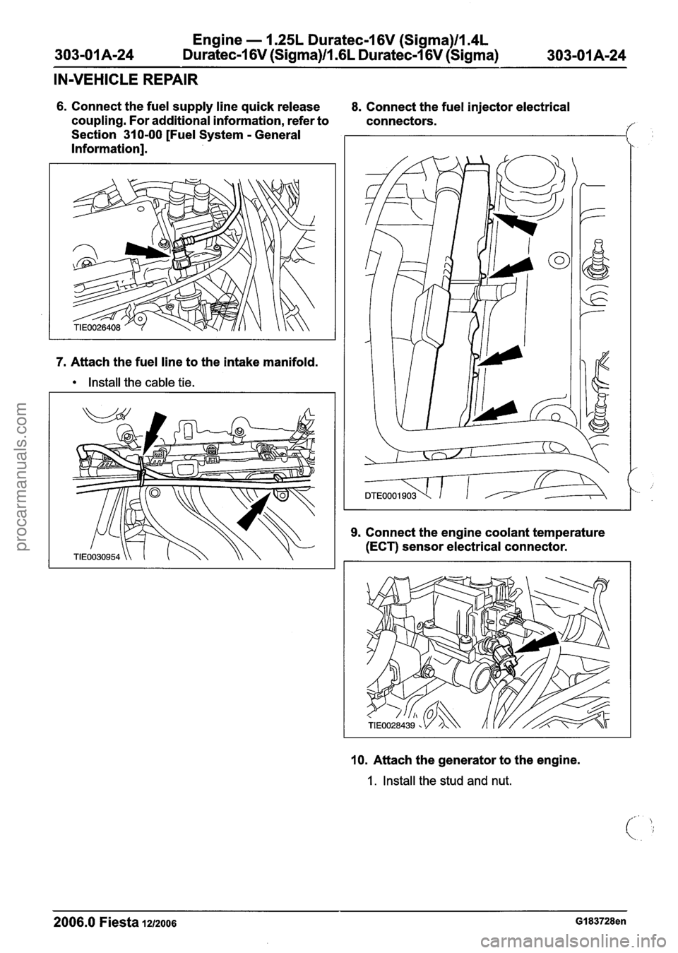
Engine - 1.25L Duratec-1 6V (Sigma)llI4L
Duratec-1 6V (Sigma)/l .6L Duratec-1 6V (Sigma)
IN-VEHICLE REPAIR
6. Connect the fuel supply line quick release
coupling. For additional information, refer to
Section 310-00 [Fuel System
- General
Information].
7. Attach the fuel line to the intake manifold.
Install the cable tie. 8.
Connect the fuel injector electrical
connectors.
9. Connect the engine coolant temperature
(ECT) sensor electrical connector.
10. Attach the generator to the engine.
1. Install the stud and nut.
2006.0 Fiesta 1212006 GI 83728en
procarmanuals.com
Page 532 of 1226
Engine - 1.25L Duratec-1 6V (Sigma)ll.4L
303-01 A-56 Duratec-1 6V (Sigma)ll .6L Duratec-1 6V (Sigma) 303-01 A-56
IN-VEHICLE REPAIR
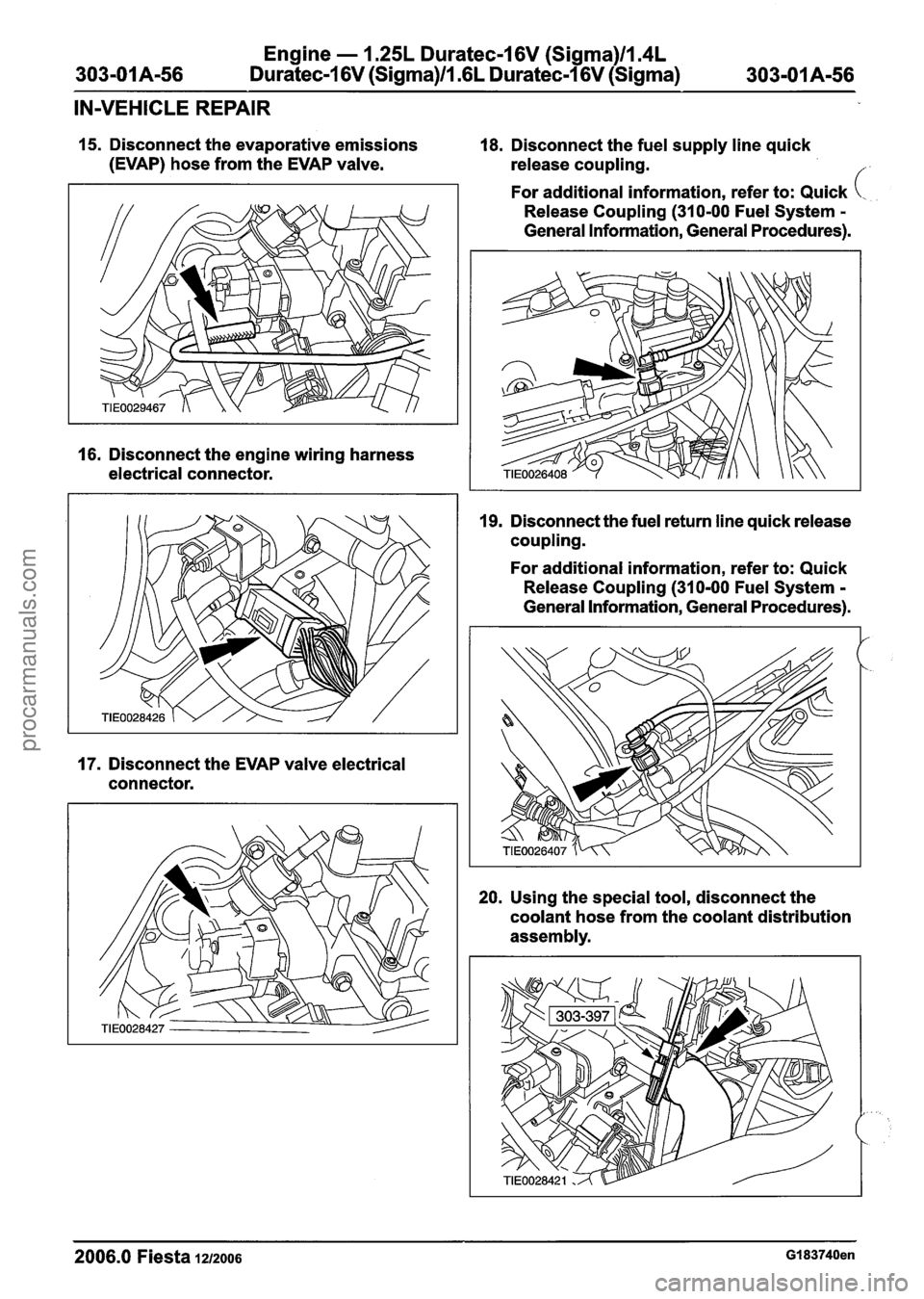
15. Disconnect the evaporative emissions 18. Disconnect the fuel supply line quick
(EVAP) hose from the EVAP valve.
release coupling.
f
16. Disconnect the engine wiring harness
electrical connector.
17. Disconnect the EVAP valve electrical
connector. For
additional information, refer to: Quick
(..
Release Coupling (310-00 Fuel System -
General Information, General Procedures).
I 9. Disconnect the fuel return line quick release
coupling.
For additional information, refer to: Quick
Release Coupling
(31 0-00 Fuel System -
General Information, General Procedures).
20. Using the special tool, disconnect the
coolant hose from the coolant distribution
assembly.
2006.0 Fiesta 1212006 GI 83740en
procarmanuals.com
Page 537 of 1226
Engine - 1.25L Duratec-1 6V (Sigma)ll.4L
303-01A-61 Duratec-1 6V (Sigma)/l .6L Duratec-I 6V (Sigma) 303-OIA-61
IN-VEHICLE REPAIR
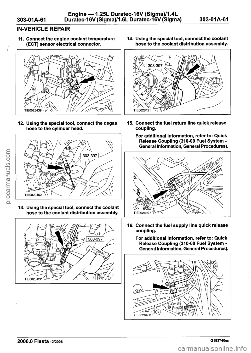
11. Connect the engine coolant temperature 14.
Using the special tool, connect the coolant
/ (ECT) sensor electrical connector.
hose to the coolant distribution assembly.
12. Using the special tool, connect the degas 15.
Connect the fuel return line quick release
hose to the cylinder head. coupling.
13. Using the special tool, connect the coolant
hose to the coolant distribution assembly. For additional
information, refer to: Quick
Release Coupling (310-00 Fuel System
-
General Information, General Procedures).
16. Connect the fuel supply line quick release
coupling.
For additional information, refer to: Quick
Release Coupling (310-00 Fuel System
-
General Information, General Procedures).
2006.0 Fiesta 1212006 GI 83740en
procarmanuals.com
Page 547 of 1226
Engine - I .25L Duratec-1 6V (Sigma)ll.4L
Duratec-1 6V (Sigma)ll .6L Duratec-1 6V (Sigma)
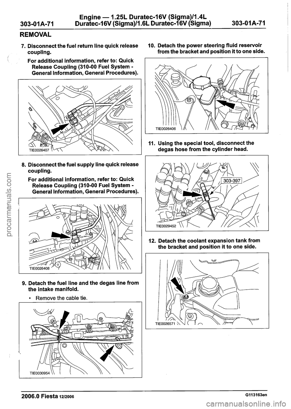
REMOVAL
7. Disconnect the fuel return line quick release 10. Detach the power steering fluid reservoir
coupling. from
the bracket and position
it to one side.
i For additional information, refer to: Quick
Release Coupling
(310-00 Fuel System -
General Information, General Procedures).
8. Disconnect the fuel supply line quick release
coupling.
For additional information, refer to: Quick
Release Coupling
(310-00 Fuel System -
General Information, General Procedures).
9. Detach the fuel line and the degas line from
the intake manifold.
Remove the cable tie. 11.
Using
the special tool, disconnect the
degas hose from the cylinder head.
12. Detach the coolant expansion tank from
the bracket and position
it to one side.
2006.0 Fiesta 1212006 GI 131 63en
procarmanuals.com