Injector FORD FIESTA 2007 User Guide
[x] Cancel search | Manufacturer: FORD, Model Year: 2007, Model line: FIESTA, Model: FORD FIESTA 2007Pages: 1226, PDF Size: 61.26 MB
Page 707 of 1226
303-01 B-85 Engine - 2.OL Duratec-HE (M14) 303-01 B-85
DISASSEMBLY
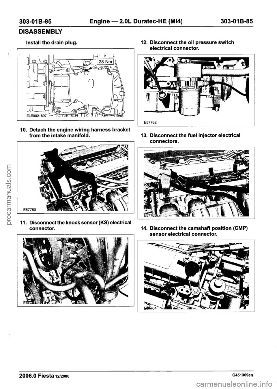
Install the drain plug. 12.
Disconnect the oil pressure switch
electrical connector.
10. Detach the engine wiring harness bracket
from the intake manifold. 13.
Disconnect the fuel injector electrical
connectors.
11. Disconnect the knock sensor
(KS) electrical
connector. 14.
Disconnect the camshaft position
(CMP)
sensor electrical connector.
2006.0 Fiesta 1212006 G451309en
procarmanuals.com
Page 730 of 1226
303-01 B-I08 Engine - 2.OL Duratec-HE (M14) 303-01 B-108
ASSEMBLY
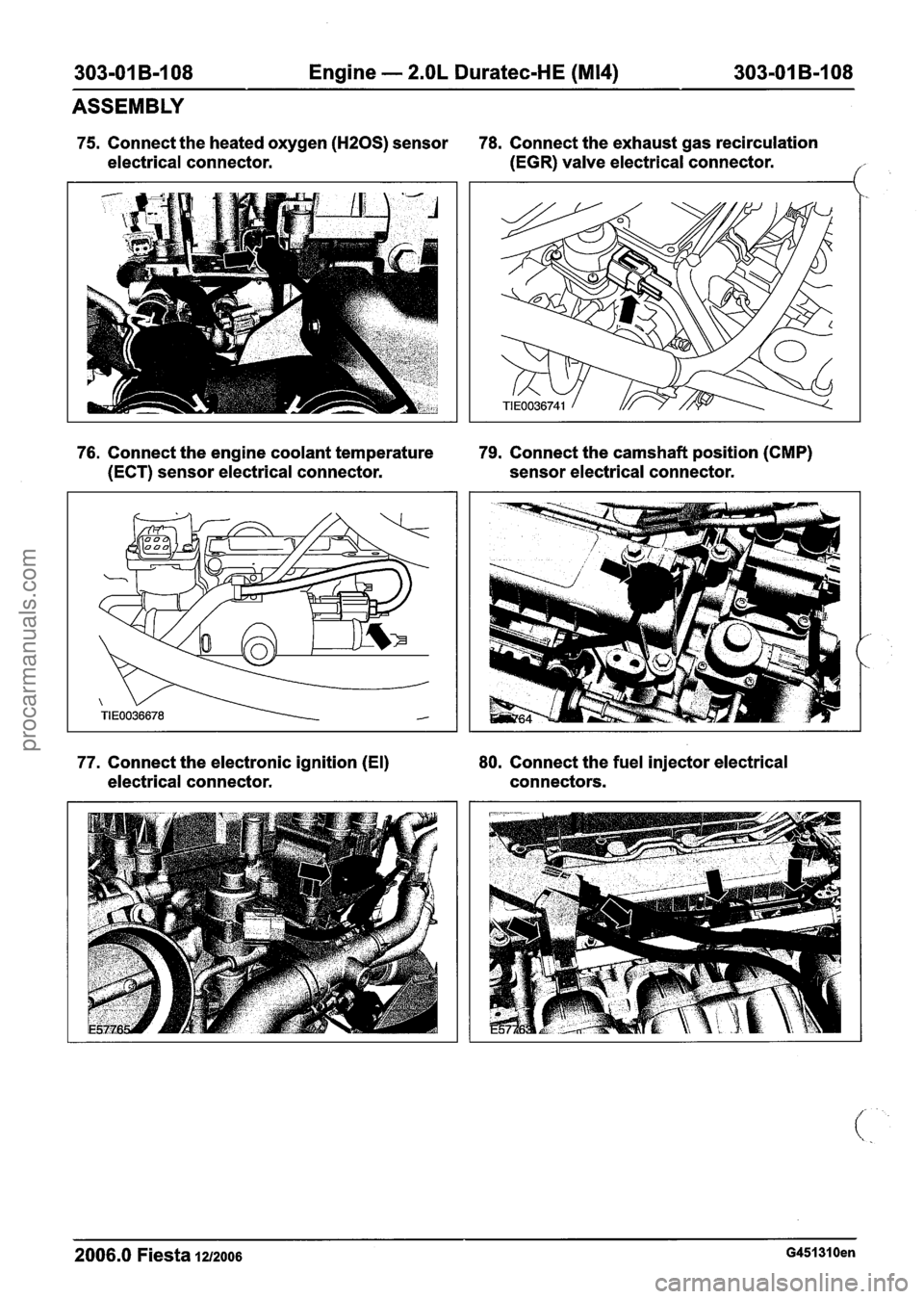
75. Connect the heated oxygen (HZOS) sensor 78. Connect the exhaust gas recirculation
electrical connector. (EGR)
valve electrical connector.
('
76. Connect the engine coolant temperature 79. Connect the camshaft position (CMP)
(ECT) sensor electrical connector. sensor electrical connector.
77. Connect the electronic ignition (El) 80.
Connect the fuel injector electrical
electrical connector. connectors.
2006.0 Fiesta 1212006 G451310en
procarmanuals.com
Page 801 of 1226
Fuel Charging and Controls - 1.25L
Duratec-1 6V (Sigma)ll.4L Duratec-1 6V
303-04A-3 (Sigma)ll .6L Duratec-1 6V (Sigma) 303-04A-3 - -
DIAGNOSIS AND TESTING
Fuel Charging and Controls
Principles Of Operation
REFER to: Acceleration Control (31 0-02A,
Diagnosis and Testing).
lnspection and Verification
1. Verify the customer concern.
2. Visually inspect for obvious signs of mechanical
or electrical damage.
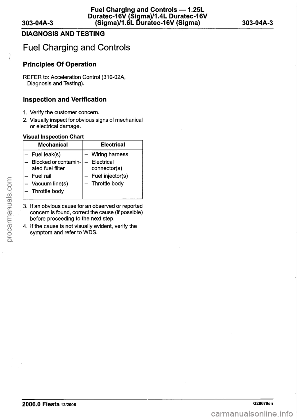
Visual Inspection Chart
I Mechanical I Electrical I
- Fuel leak(s)
- Blocked or contamin-
ated fuel filter
- Fuel rail
- Vacuum line(s)
- Throttle body
- Wiring harness
- Electrical
connector(s)
- Fuel injector(s)
- Throttle body
I
3. If an obvious cause for an observed or reported
concern is found, correct the cause (if possible)
before proceeding to the next step.
4. If the cause is not visually evident, verify the
symptom and refer to WDS.
2006.0 Fiesta 1212006 G28679en
procarmanuals.com
Page 804 of 1226
Fuel Charging and Controls - 1.25L
Duratec-1 6V (Sigma)ll.4L Duratec-1 6V
(Sigma)ll .6L Duratec-1 6V (Sigma)
REMOVAL AND INSTALLATION
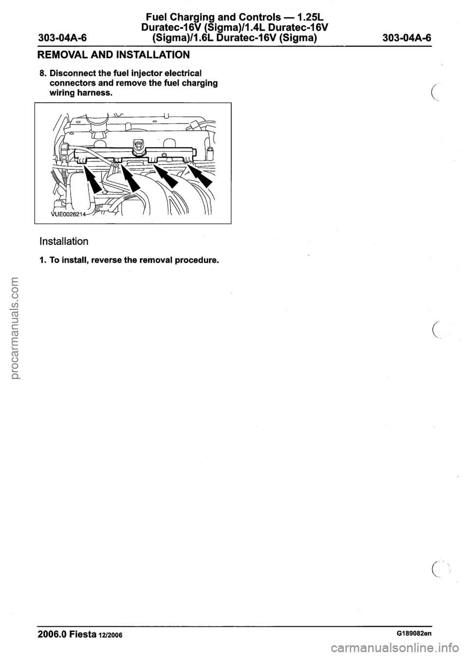
8. Disconnect the fuel injector electrical
connectors and remove the fuel charging
wiring harness.
Installation
I. To install, reverse the removal procedure.
2006.0 Fiesta 1212006 GI 89082en
procarmanuals.com
Page 805 of 1226
Fuel Charging and Controls - 1.25L
Duratec-1 6V (Sigma)llI4L Duratec-1 6V
303-04A-7 (Sigma)llI6L Duratec-1 6V (Sigma) 303-04A-7
REMOVAL AND INSTALLATION
Fuel Injection Supply Manifold(23 450 0)
Removal
WARNINGS:
A Do not smoke or carry lighted tobacco or
open flame of any type when working on
or near any fuel related components.
Highly flammable vapors are always
present and can ignite. Failure to follow
these instructions may result in personal
injury.
A This procedure involves fuel handling. Be
prepared for fuel spillage at all times and
always observe fuel handling precautions.
Failure to follow these instructions may
result in personal injury.
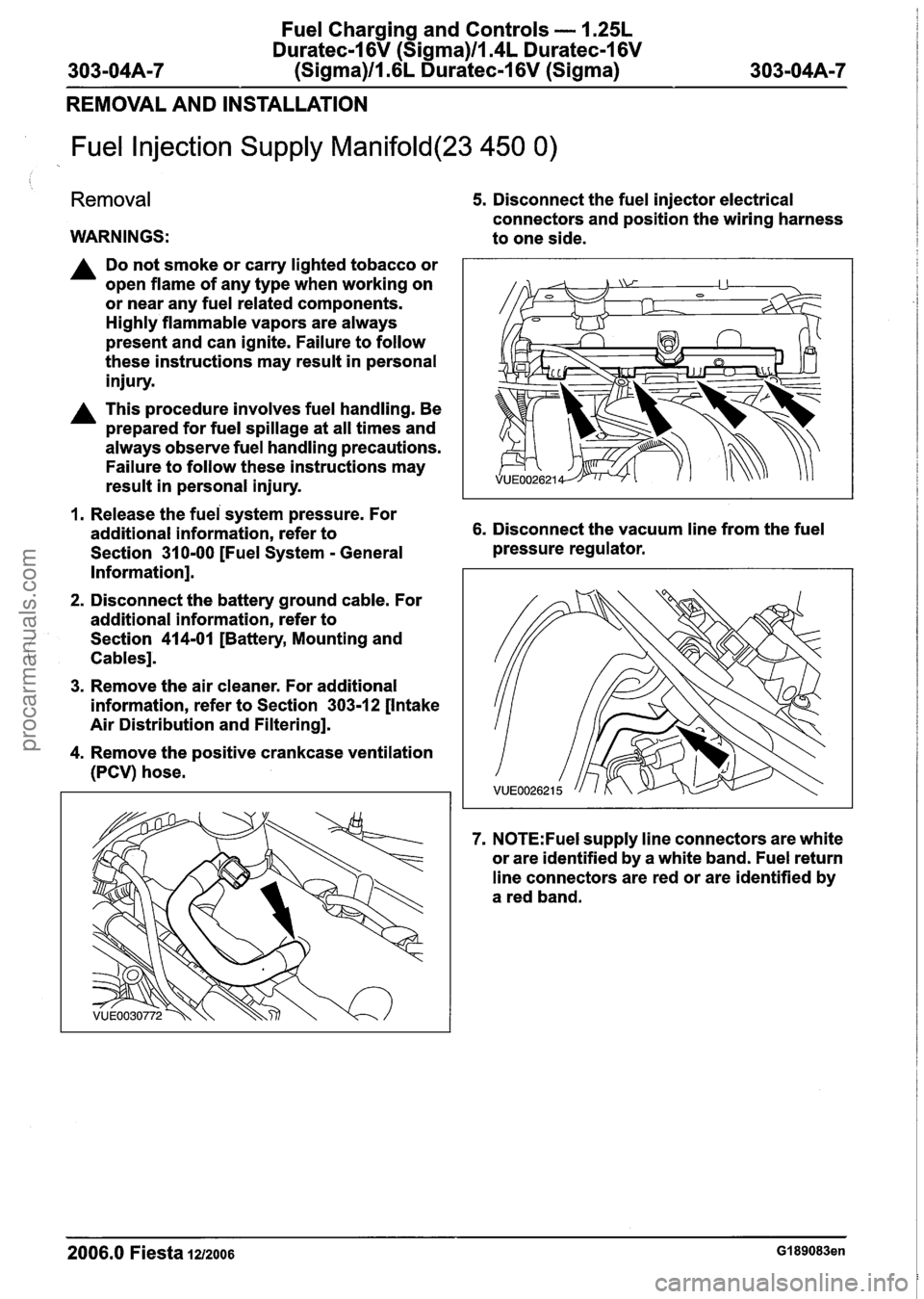
5. Disconnect the fuel injector electrical
connectors and position the wiring harness
to one side.
1. Release the fuei system pressure. For
additional information, refer to 6. Disconnect the vacuum line from the fuel
Section
31 0-00 [Fuel System - General pressure
regulator.
Information].
2. Disconnect the battery ground cable. For
additional information, refer to
Section
414-01 [Battery, Mounting and
Cables].
3. Remove the air cleaner. For additional
information, refer to Section
303-12 [Intake
Air Distribution and Filtering].
4. Remove the positive crankcase ventilation
(PCV) hose.
7. N0TE:Fuel supply line connectors are white
or are identified by a white band. Fuel return
line connectors are red or are identified by
a red band.
2006.0 Fiesta 1212006 GI 89083en
procarmanuals.com
Page 806 of 1226
Fuel Charging and Controls - 1.25L
Duratec-I 6V (Sigma)ll.4L Duratec-I 6V
(Sigma)ll.6L Duratec-1 6V (Sigma)
REMOVAL AND INSTALLATION
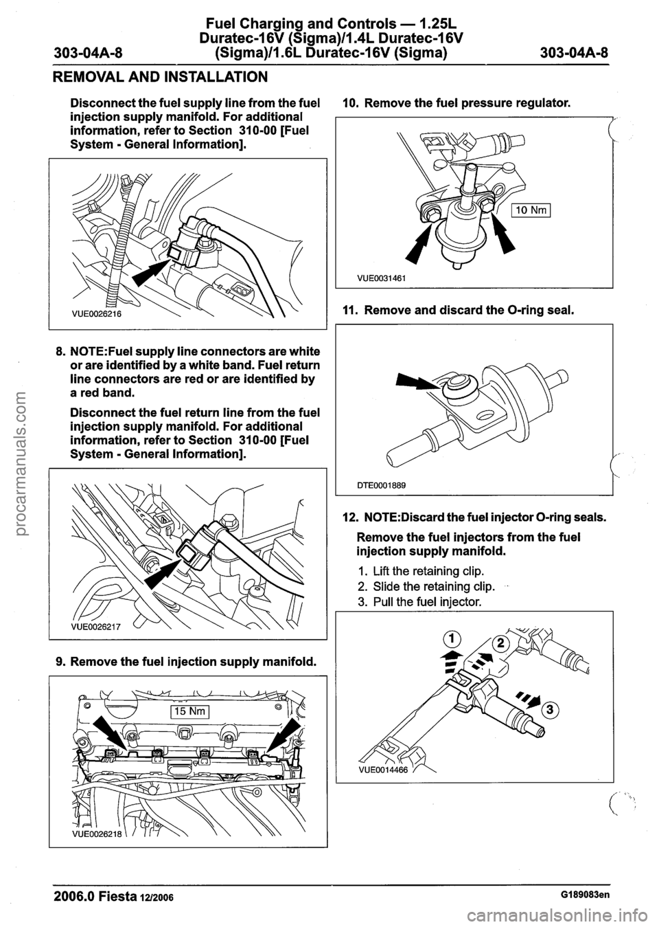
Disconnect the fuel supply line from the fuel 10. Remove the fuel pressure regulator.
injection supply manifold. For additional
information, refer to Section 31 0-00 [Fuel
System
- General Information].
8. N0TE:Fuel supply line connectors are white
or are identified by a white band. Fuel return
line connectors are red or are identified by
a red band.
Disconnect the fuel return line from the fuel
injection supply manifold. For additional
information, refer to Section 31 0-00 [Fuel
System
- General Information].
9. Remove the fuel injection supply manifold.
11. Remove and discard the O-ring seal.
12.
N0TE:Discard the fuel injector O-ring seals.
Remove the fuel injectors from the fuel
injection supply manifold.
1. Lift the retaining clip.
2. Slide the retaining clip. .
3. Pull the fuel injector.
2006.0 Fiesta 1212006 GI 89083en
procarmanuals.com
Page 807 of 1226
Fuel Charging and Controls - 1.25L
Duratec-I 6V (Sigma)llI4L Duratec-1 6V
303-04A-9 (Sigma)ll .6L Duratec-1 6V (Sigma) 303-04A-9
REMOVAL AND INSTALLATION
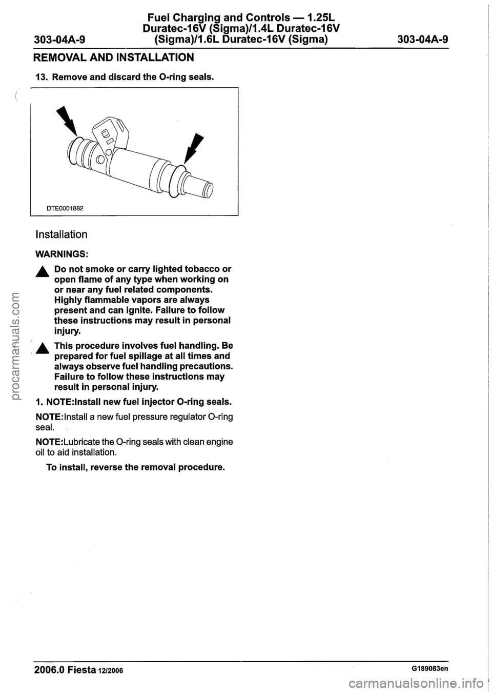
13. Remove and discard the O-ring seals.
Installation
WARNINGS:
A Do not smoke or carry lighted tobacco or
open flame of any type when working on
or near any fuel related components.
Highly flammable vapors are always
present and can ignite. Failure to follow
these instructions may result in personal
injury.
( A This procedure involves fuel handling. Be ' prepared for fuel spillage at all times and
always observe fuel handling precautions.
Failure to follow these instructions may
result in personal injury.
1. N0TE:lnstall new fuel injector O-ring seals.
N0TE:lnstall a new fuel pressure regulator O-ring
seal.
.
N0TE:Lubricate the O-ring seals with clean engine
oil to aid installation.
To install, reverse the removal procedure.
2006.0 Fiesta IZIZOO~ GI 89083en
procarmanuals.com
Page 809 of 1226

Fuel Charging and Controls - 2.OL
Duratec-HE (M14)
I SECTION 303-04B Fuel Charging and Controls - 2.OL
Duratec-HE (M14)
VEHICLE APPLICATION:2006.0 Fiesta
CONTENTS PAGE
SPECIFICATIONS
........................................................................\
............................................ Specifications.. 303-04B-2
DESCRIPTION AND OPERATION
Fuel Charging and Controls ........................................................................\
.................... 303-048-3
DIAGNOSIS AND TESTING
Fuel Charging and Controls ........................................................................\
.................... 303-04B-5
Principles of Operation
........................................................................\
........................... 303-04B-5
Inspection and Verification
........................................................................\
.......................... 303-048-8
Symptom Chart ........................................................................\
...................................... 303-04B-9
REMOVAL AND INSTALLATION /
(< Throttle Body 303-048-24 ........................................................................\
..............................................
Fuel Injectors ........................................................................\
.......................... (23 455 0) 303-048-26
Fuel Rail ........................................................................\
...................................................... 303-04B-27
procarmanuals.com
Page 811 of 1226
Fuel Charging and Controls - 2.OL
Duratec-HE (M14)
DESCRIPTION AND OPERATION
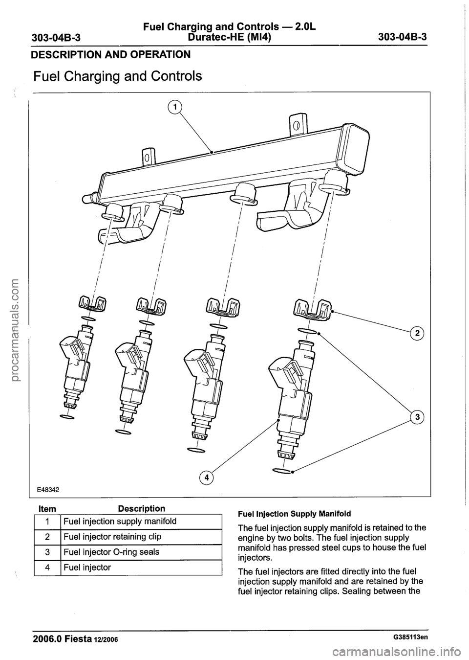
Fuel Charging and Controls
Item Description Fuel Injection Supply Manifold
4 1 Fuel injector
The fuel injectors are fitted directly into the fuel
injection supply manifold and are retained by the
3
fuel injector retaining clips. Sealing between the
The fuel
injection supply manifold is retained to the
engine by two bolts. The fuel injection supply
1
2
2006.0 Fiesta 1212006 G385113en
Fuel injection supply manifold
Fuel injector retaining clip
Fuel injector O-ring seals manifold-has pressed steel
cups to
house the fuel
injectors.
procarmanuals.com
Page 812 of 1226
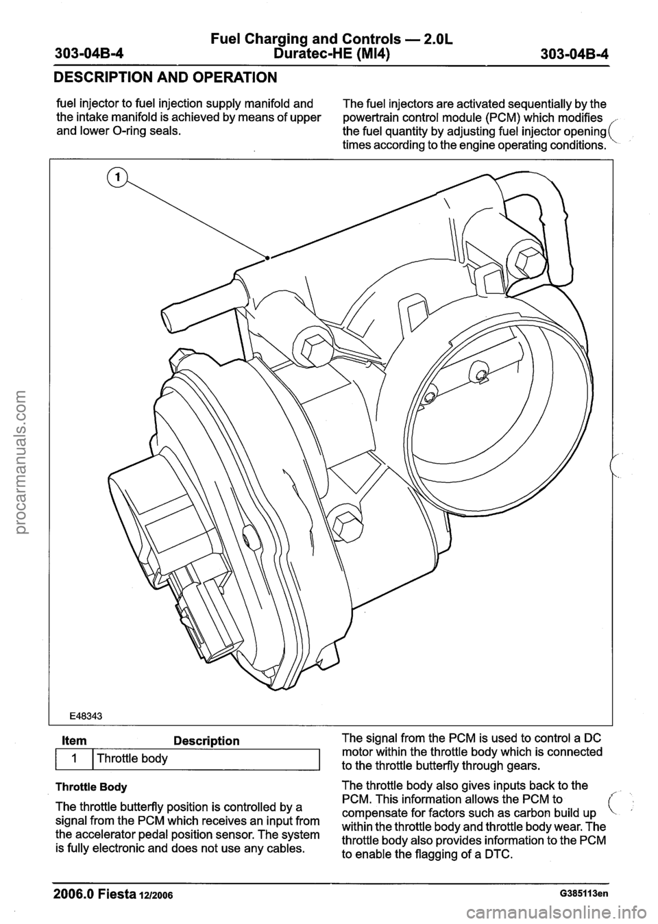
Fuel Charging and Controls - 2.OL
303-04B-4 Duratec-HE (M14) 303-04B-4
DESCRIPTION AND OPERATION
fuel injector to fuel injection supply manifold and
The fuel injectors are activated sequentially by the
the intake manifold is achieved by means of upper
powertrain control module (PCM) which modifies
and lower O-ring seals.
the fuel quantity by adjusting fuel injector opening
times according to the engine operating conditions.
Throttle Body The throttle body also gives inputs back to the
Item Description The signal from the PCM is used to control a DC
The throttle butterfly position is controlled by a
signal from the PCM which receives an input from
the accelerator pedal position sensor. The system
is fully electronic and does not use any cables.
I
PCM. This information allows the PCM to
compensate for factors such as carbon build up
within the throttle body and throttle body wear. The
throttle body also provides information to the PCM
to enable the flagging of a DTC.
Throttle
body
2006.0 Fiesta 1212006 G385113en
motor within the throttle body which is connected
to the throttle butterfly through gears.
procarmanuals.com