Injector FORD FIESTA 2007 Workshop Manual
[x] Cancel search | Manufacturer: FORD, Model Year: 2007, Model line: FIESTA, Model: FORD FIESTA 2007Pages: 1226, PDF Size: 61.26 MB
Page 29 of 1226
100-00-1 3 General Information 100-00-1 3
DESCRIPTION AND OPERATION
Do not use damaged or defective tools or
equipment, particularly high-speed equipment such
i as grinding wheels. A damaged grinding wheel can
disintegrate without warning and cause serious
injury.
Wear suitable eye protection when using grinding,
chiseling or sand blasting equipment.
Wear a suitable breathing mask when using
abrasive blasting equipment, working with
asbestos-based materials or using spraying
equipment.
Make sure there is adequate ventilation to control
dusts, mists and fumes.
High Pressure Air, Lubrication and Oil
Test Equipment
See also Lubricants and Greases.
Always keep high-pressure equipment in good
condition, and regularly maintained, particularly at
joints and unions.
Never direct a high-pressure nozzle, for example
diesel injector, at the skin as the fluid may
, penetrate to the underlying tissue, and cause
serious injury.
Halon
See CFCs.
Legal Aspects
There are many laws and regulations relating to
health and safety in the use and disposal of
materials and equipment in a workshop.
For a safe working environment and to avoid
environmental pollution, workshops should be
familiar, in detail, with the many health and safety
laws and regulations within their country, published
by both national and local authorities.
Lubricants and Greases
Avoid all prolonged and repeated contact with
mineral oils. All lubricants and greases may be
irritating to the eyes and skin.
'
Transmission Fluids
Safety instructions
Certain Transmission and Power Steering fluids
supplied to Ford may contain additives which have
the potential to cause skin disease (dermatitis) to
exposed persons. The dermatitis may be irritant
or allergic in nature. Risks are higher where
prolonged or repeated skin contact with a fluid may
occur. These fluids are used for vehicle initial
fill
and service purposes. This sub-section is to:
Inform Service personnel who may come into
contact with these vehicle fluids (hazard
communication).
Summarise appropriate workplace control
measures and personal protective equipment
requirements.
Draw attention to the existence of Material
Safety Datasheets (MSDS's) for the fluids
(available from Ford Customer Service Division).
These MSDS's contain detailed information on
hazards and appropriate controls.
Control measures
Workplace risk assessments made under national
chemical control regulations should identify
operations involving the fluids as potentially
hazardous and specify workplace control and
worker awareness measures. In such
circumstances, the relevant Material Safety
Datasheet (see the details specified below) which
specifies hazards and control measures in detail
should be made available for guidance.
Avoid unprotected skin contact with the fluids, and
in particular, avoid prolonged or repeated skin
contact. Work practices should be organised so as
to minimise the potential for skin contact. This may
include the use of drip trays, absorbents, correct
fluid handling equipment (funnels etc), and
workplace housekeeping measures such as the
cleaning of contaminated surfaces.
Personnel engaged in operations where skin
contact could occur (such as fluid draining or filling)
should wear impervious gloves made from
nitrile
rubber, certified to a chemical protection standard,
e.g. Europe Standard EN374. This glove type is
widely available from reputable suppliers of gloves
for chemical protection [including the manufacturers
Ansell-Admont
(Solvex Range), North Safety
products (North
Nitrile Latex Gloves range), and
2006.0 Fiesta 1212006 GI 7372en
procarmanuals.com
Page 437 of 1226
303-00-1 5 Engine System - General Information 303-00-1 5
DIAGNOSIS AND TESTING
N0TE:The varying design of compression checking
% devices and fluctuating starter motor speeds
normally only allows for a comparison to be made
of the compression pressures in all cylinders.
Measure the compression pressure
Engine
- 1.4L Duratorq-TDCi (DV)
biesel)
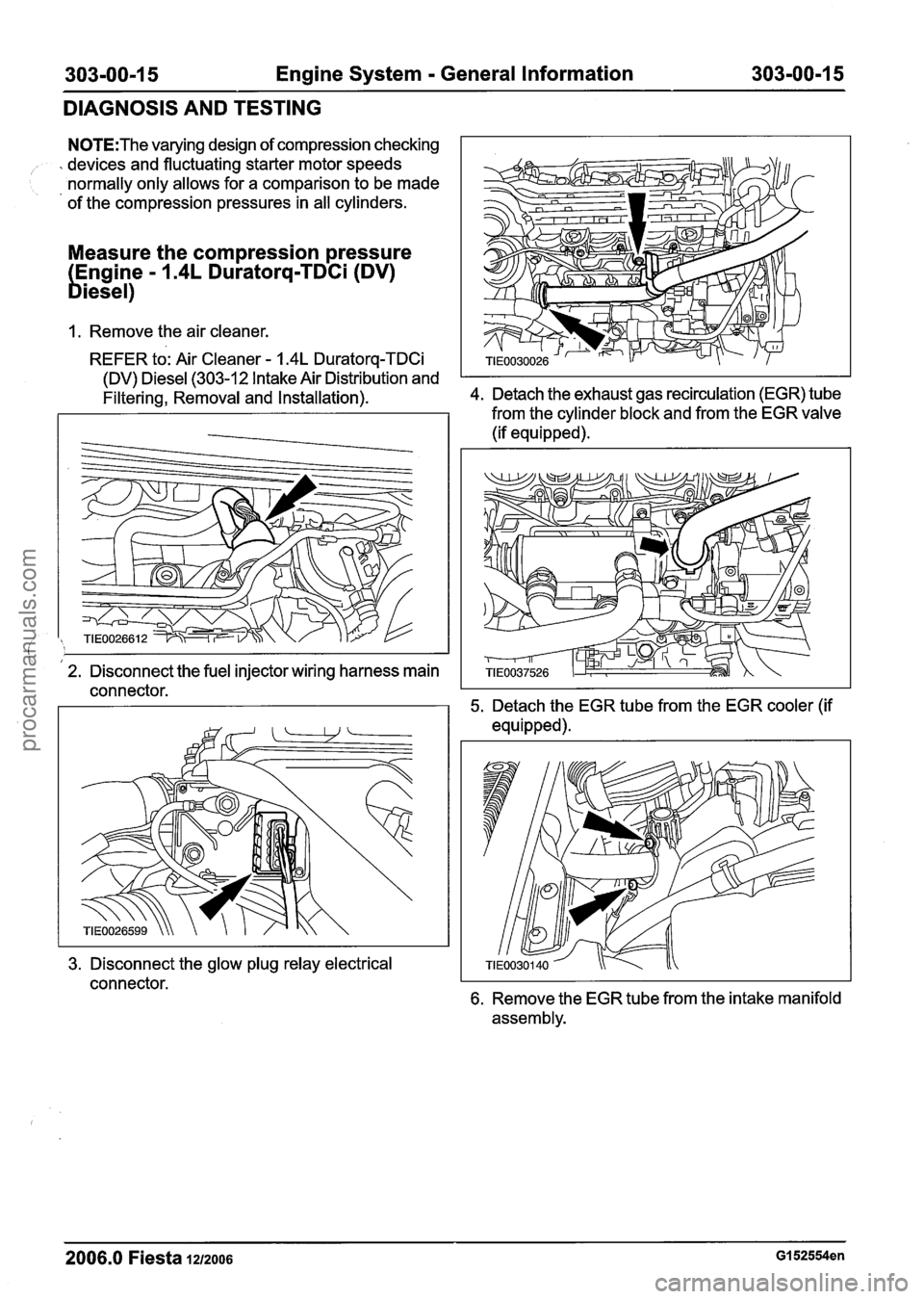
1. Remove the air cleaner.
REFER to: Air Cleaner
- 1.4L Duratorq-TDCi
(DV) Diesel (303-12 Intake Air Distribution and
Filtering, Removal and
Installation). 4. Detach the exhaust gas recirculation (EGR) tube
from the cylinder block and from the EGR valve
(if equipped).
I I 2. Disconnect the fuel injector wiring harness main
connector. 5. Detach the EGR tube from the EGR cooler (if
equipped).
3. Disconnect the glow plug relay electrical
connector.
6. Remove the EGR tube from the intake manifold
assembly.
2006.0 Fiesta 1212006 GI 52554en
procarmanuals.com
Page 439 of 1226
303-00-1 7 Engine System - General Information 303-00-1 7
DIAGNOSIS AND TESTING
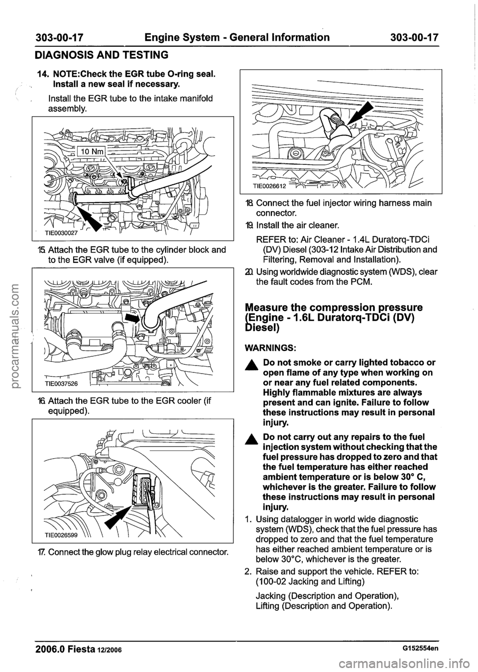
14. N0TE:Check the EGR tube O-ring seal.
Install a new seal
if necessary. I
, Install the EGR tube to the intake manifold
assembly.
18 Connect the fuel injector wiring harness main
connector.
19 Install the air cleaner.
REFER to: Air Cleaner
- 1.4L Duratorq-TDCi
15 Attach the EGR tube to the cylinder block and (DV) Diesel (303-12 Intake Air Distribution
and
to the EGR valve (if equipped). Filtering, Removal
and Installation).
Using worldwide diagnostic system (WDS), clear
the fault codes from the PCM.
Measure the compression pressure
Engine
- 1.6L Duratorq-TDCi (DV)
biesel)
WARNINGS:
A Do not smoke or carry lighted tobacco or
open flame of any type when working on
or near any fuel related components.
Highly flammable mixtures are always
16 Attach the EGR tube to the EGR cooler (if present and can ignite. Failure to follow
equipped). these instructions may result in personal
injury.
Do not carry out any repairs to the fuel
injection system without checking that the
fuel pressure has dropped to zero and that
the fuel temperature has either reached
ambient temperature or is below
30' C,
whichever is the greater. Failure to follow
these instructions may result in personal
injury.
I. Using datalogger in world wide diagnostic
system (WDS), check that the fuel pressure has
dropped to zero and that the fuel temperature
17. Connect the glow plug relay electrical connector. has
either reached ambient temperature or is
below 30°C, whichever is the greater.
2. Raise and support the vehicle. REFER to:
(1 00-02 Jacking and Lifting)
Jacking (Description and Operation),
Lifting (Description and Operation).
2006.0 Fiesta 1212006 GI 52554en
procarmanuals.com
Page 440 of 1226
303-00-1 8 Engine System - General Information 303=00-18
DIAGNOSIS AND TESTING
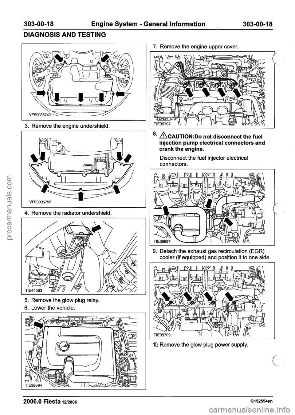
3. Remove the engine undershield.
4. Remove the radiator undershield.
7. Remove the engine upper cover.
<
8m ~CAUTION:DO not disconnect the fuel
injection pump electrical connectors and
crank the engine.
Disconnect the fuel injector electrical
connectors.
9. Detach the exhaust gas recirculation (EGR)
cooler (if equipped) and position it to one side.
5. Remove the glow plug relay.
6. Lower the vehicle.
1Q Remove the glow plug power supply.
2006.0 Fiesta 1212006 GI 52554en
procarmanuals.com
Page 441 of 1226
303-00-1 9 Engine System - General Information 303-00-1 9
DIAGNOSIS AND TESTING
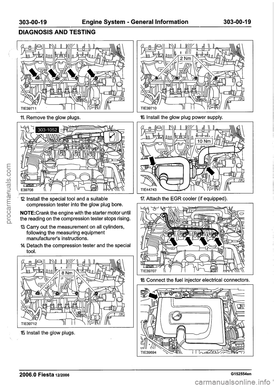
11. Remove the glow plugs. 16 Install the glow plug power supply.
I ' I2 Install the special tool and a suitable IT Attach the EGR cooler (if equipped).
compression tester into the glow plug bore.
N0TE:Crank the engine with the starter motor until
the reading on the compression tester stops rising.
13 Carry out the measurement on all cylinders,
following the measuring equipment
manufacturer's instructions.
$4 Detach the compression tester and the special
tool.
15 Install the glow plugs.
18. Connect the fuel injector electrical connectors.
I
2006.0 Fiesta 1212006 GI 52554en
procarmanuals.com
Page 497 of 1226
Engine - 1.25L Duratec-I 6V (Sigma)ll14L
Duratec-1 6V (Sigma)ll16L Duratec-1 6V (Sigma)
IN-VEHICLE REPAIR
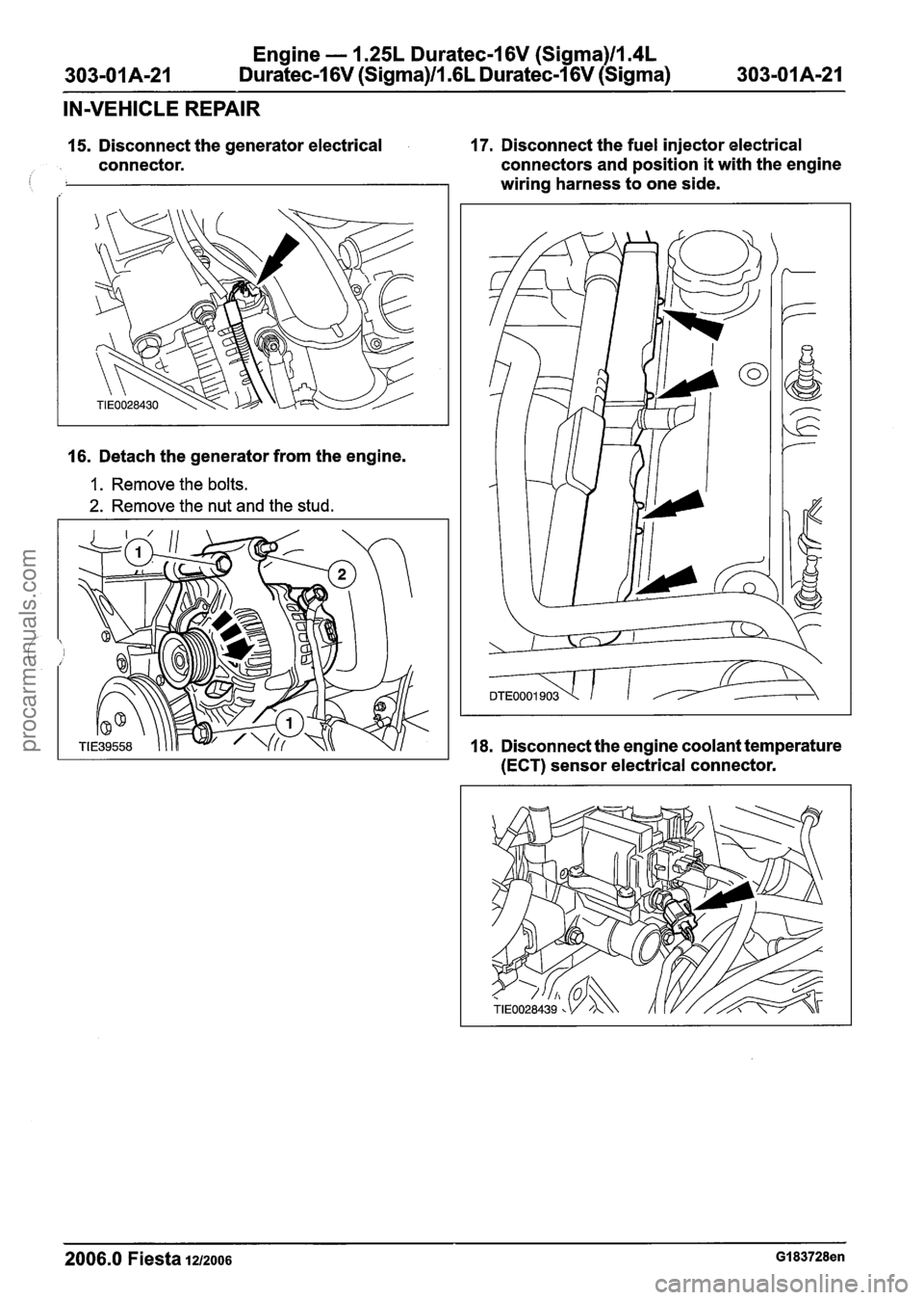
15. Disconnect the generator electrical 17. Disconnect the fuel injector electrical
connector. connectors and
position it with the engine
i wiring harness to one side.
16. Detach the generator from the engine.
1. Remove the bolts.
2. Remove the nut and the stud.
18. Disconnect the engine coolant temperature
(ECT) sensor electrical connector.
2006.0 Fiesta 1~12006 GI 83728en
procarmanuals.com
Page 499 of 1226
Engine - 1.25L Dura
303-01 A-23 Duratec-1
6V (Sigma)ll .(
:ec-I 6V (Sigma)llm4L
L
Duratec-1 6V (Sigma)
303-01 Am23
IN-VEHICLE REPAIR
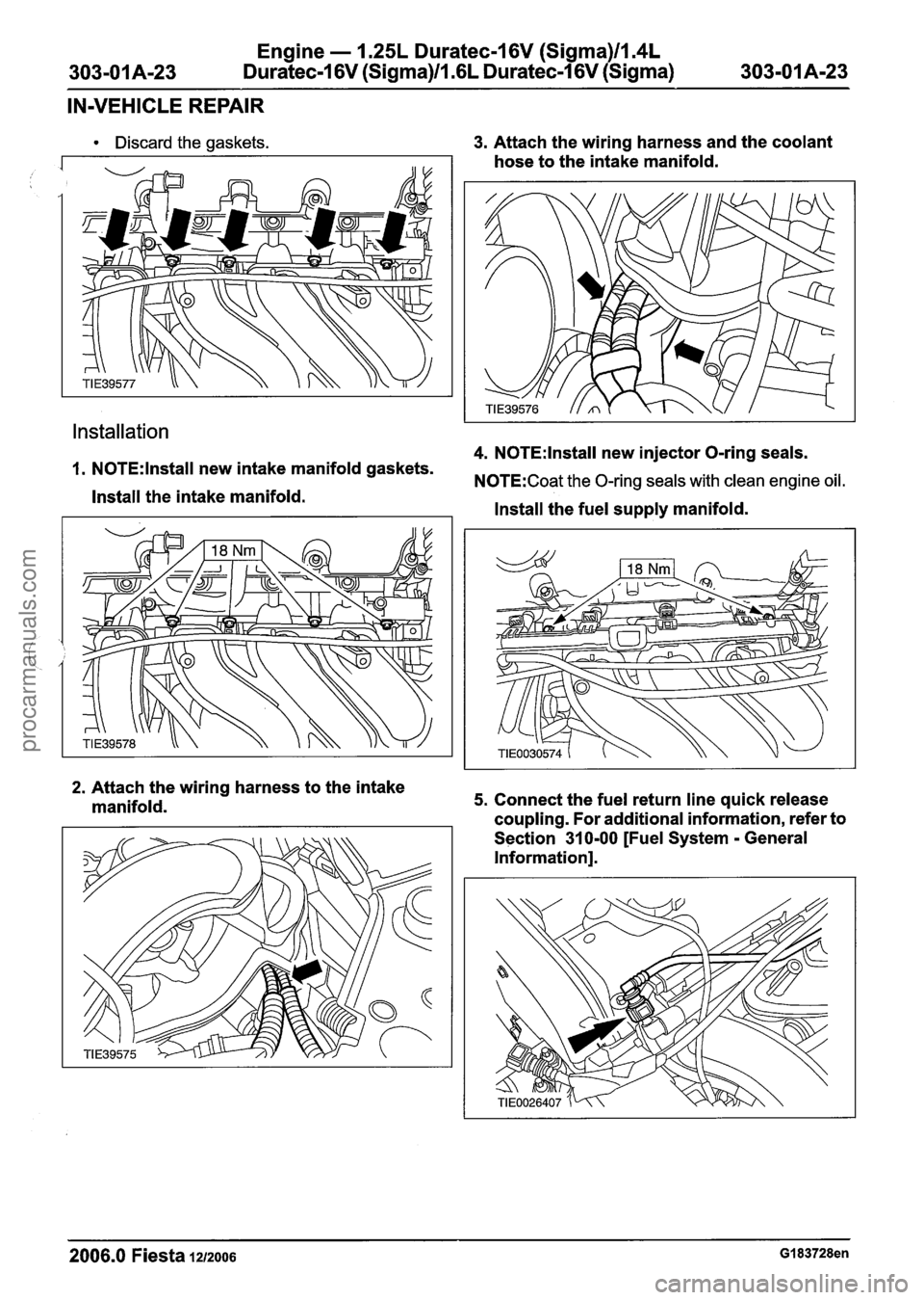
Discard the gaskets.
Installation
3. Attach the wiring harness and the coolant
hose to the intake manifold.
4. N0TE:lnstall new injector O-ring seals.
1. N0TE:lnstall new intake manifold gaskets. N0TE:Coat the 0-rina seals with clean enaine oil.
Install the intake manifold. V "
Install the fuel supply manifold.
2. Attach the wiring harness to the intake
manifold. 5. Connect the fuel return line quick release
coupling. For additional information, refer to
Section
31 0-00 [Fuel System - General
Information].
2006.0 Fiesta 1212006 GI 83728en
procarmanuals.com
Page 500 of 1226
Engine - 1.25L Duratec-1 6V (Sigma)llI4L
Duratec-1 6V (Sigma)/l .6L Duratec-1 6V (Sigma)
IN-VEHICLE REPAIR
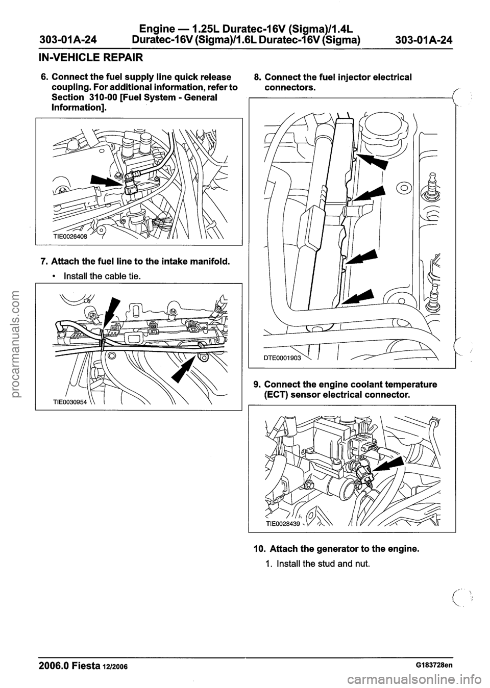
6. Connect the fuel supply line quick release
coupling. For additional information, refer to
Section 310-00 [Fuel System
- General
Information].
7. Attach the fuel line to the intake manifold.
Install the cable tie. 8.
Connect the fuel injector electrical
connectors.
9. Connect the engine coolant temperature
(ECT) sensor electrical connector.
10. Attach the generator to the engine.
1. Install the stud and nut.
2006.0 Fiesta 1212006 GI 83728en
procarmanuals.com
Page 581 of 1226
Engine - 1.25L Duratec-1 6V (Sigma)ll.4L
303-01 A-1 05 Duratec-1 6V (Sigma)/l .6L
Duratec-1 6V (Sigma) 303-01 A-1 05
DISASSEMBLY AND ASSEMBLY
OF SUBASSEMBLIES
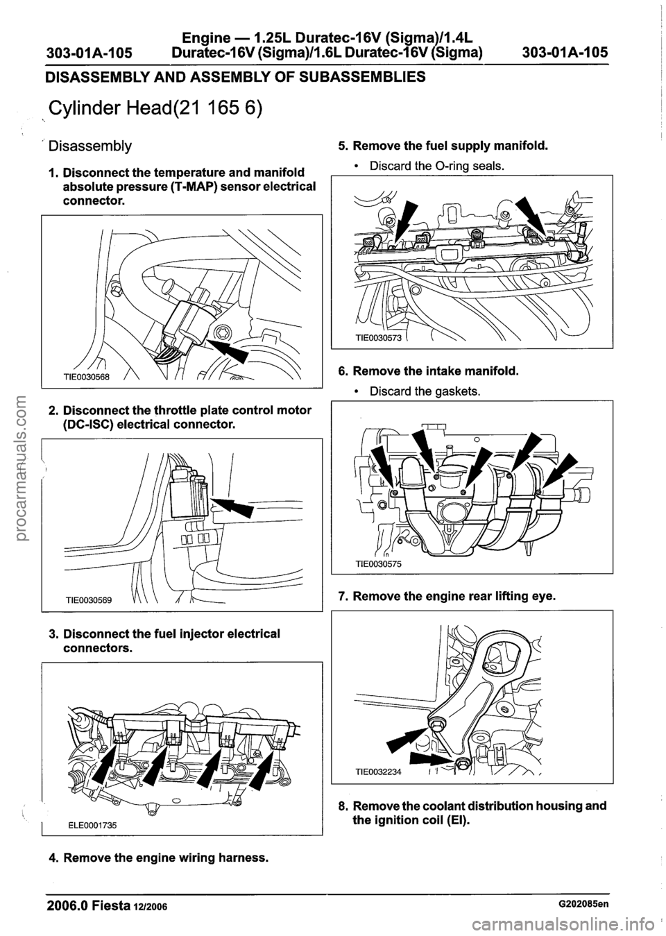
Cylinder Head(21 165 6)
' Disassembly 5. Remove the fuel supply manifold.
I. Disconnect the temperature and manifold Discard the O-ring seals.
absolute pressure (T-MAP) sensor electrical
connector.
2. Disconnect the throttle plate control motor
(DC-ISC) electrical connector.
3. Disconnect the fuel injector electrical
connectors.
6. Remove the intake manifold.
Discard the gaskets.
7. Remove the engine rear lifting eye.
8. Remove the coolant distribution housing and
1 ~~~0001735 the ignition coil (El).
4. Remove the engine wiring harness.
2006.0 Fiesta 1212006 G202085en
procarmanuals.com
Page 583 of 1226
Engine - 1.25L Duratec-1 6V (Sigma)ll.4L
303-01 A-I 07 Duratec-I 6V (Sigma)/l.GL Duratec-1 6V (Sigma)
303-01 A-I 07
DISASSEMBLY AND ASSEMBLY
OF SUBASSEMBLIES
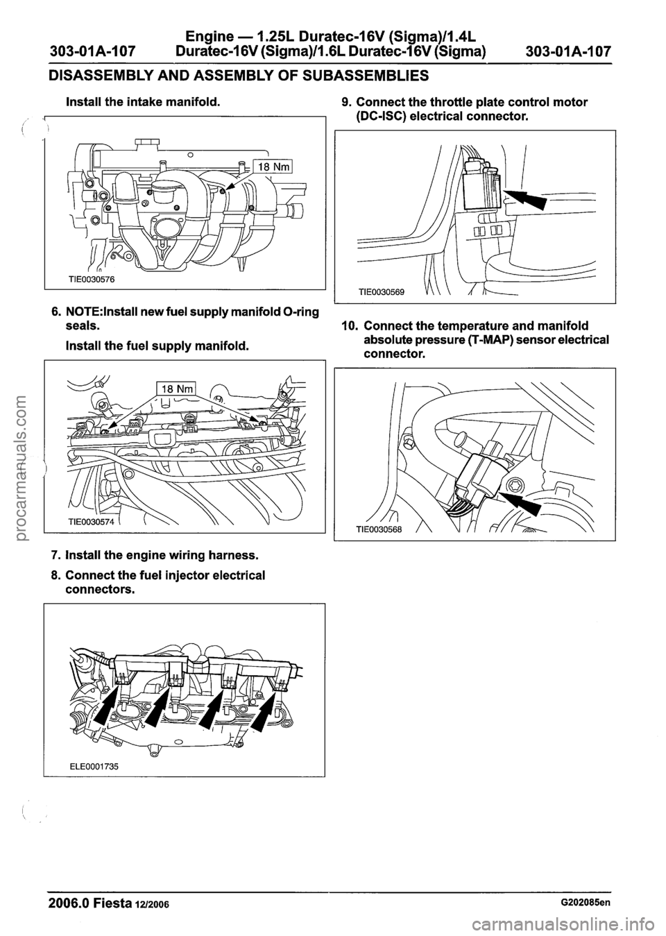
Install the intake manifold. 9. Connect the throttle plate control motor
(DC-ISC) electrical connector.
6. N0TE:lnstall new fuel supply manifold O-ring
seals.
10. Connect the temperature and manifold
Install the fuel supply manifold. absolute pressure (T-MAP)
sensor electrical
connector.
7. Install the engine wiring harness.
8. Connect the fuel injector electrical
connectors.
2006.0 Fiesta 1212006 G202085en
procarmanuals.com