jacking FORD FIESTA 2007 User Guide
[x] Cancel search | Manufacturer: FORD, Model Year: 2007, Model line: FIESTA, Model: FORD FIESTA 2007Pages: 1226, PDF Size: 61.26 MB
Page 94 of 1226
204-00-1 4 Suspension System - General Information 204-00-1 4
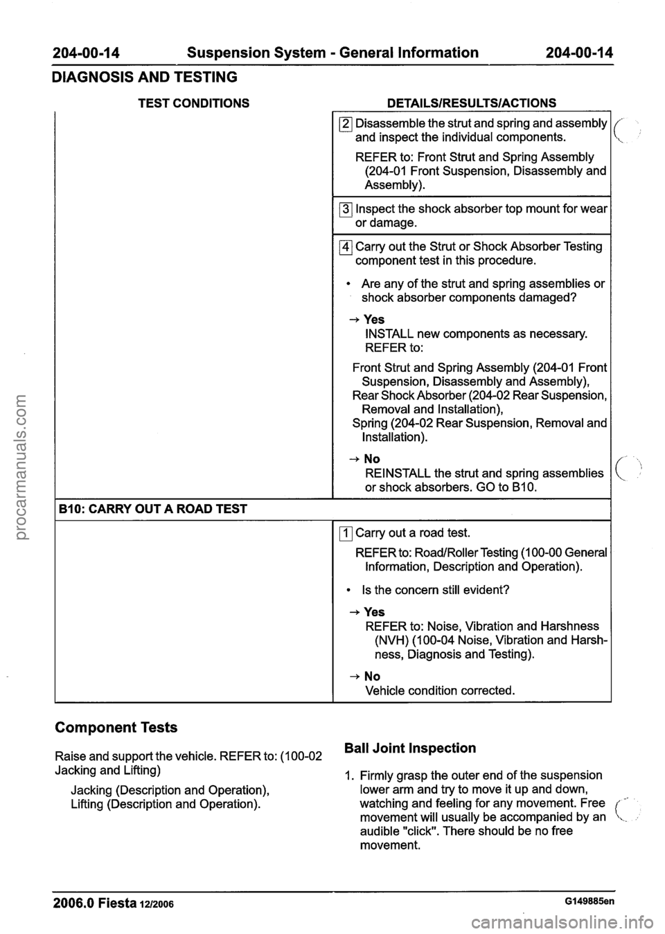
DIAGNOSIS AND TESTING
TEST CONDITIONS DETAILSIRESU LTSIACTIONS
Component Tests
Raise and support the vehicle. REFER to: (1 00-02 Ball Joint Inspection
Jacking and Lifting)
1. Firmly grasp the outer end of the suspension
Jacking (Description and Operation), lower arm and
try to move it up and down,
Lifting (Description and Operation). watching and feeling for
any movement. Free
-
movement will usually be accompanied by an !
audible "click". There should be no free
movement.
(,';
B10: CARRY OUT A ROAD TEST
2006.0 Fiesta 1212006 Gl49885en
Disassemble the strut and spring and assembly
and inspect the individual components.
REFER to: Front Strut and Spring Assembly
(204-01 Front Suspension, Disassembly and
Assembly).
Inspect the shock absorber top mount for wear
or damage.
Carry out the Strut or Shock Absorber Testing
component test in this procedure.
Are any of the strut and spring assemblies or
shock absorber components damaged?
-+ Yes
INSTALL new components as necessary.
REFER to:
Front Strut and Spring Assembly (204-01 Front
Suspension, Disassembly and Assembly),
Rear Shock Absorber (204-02 Rear Suspension, Removal and Installation),
Spring (204-02 Rear Suspension, Removal and Installation).
-, No
REINSTALL the strut and spring assemblies
or shock absorbers. GO to
B10.
Carry out a road test.
REFER to:
RoadlRoller Testing (1 00-00 General
Information, Description and Operation).
Is the concern still evident?
-+ Yes
REFER to: Noise, Vibration and Harshness
(NVH) (1 00-04 Noise, Vibration and Harsh-
ness, Diagnosis and Testing).
-+ No
Vehicle condition corrected.
procarmanuals.com
Page 96 of 1226
204-00-1 6 Suspension System - General Information 204-00-1 6
GENERAL PROCEDURES
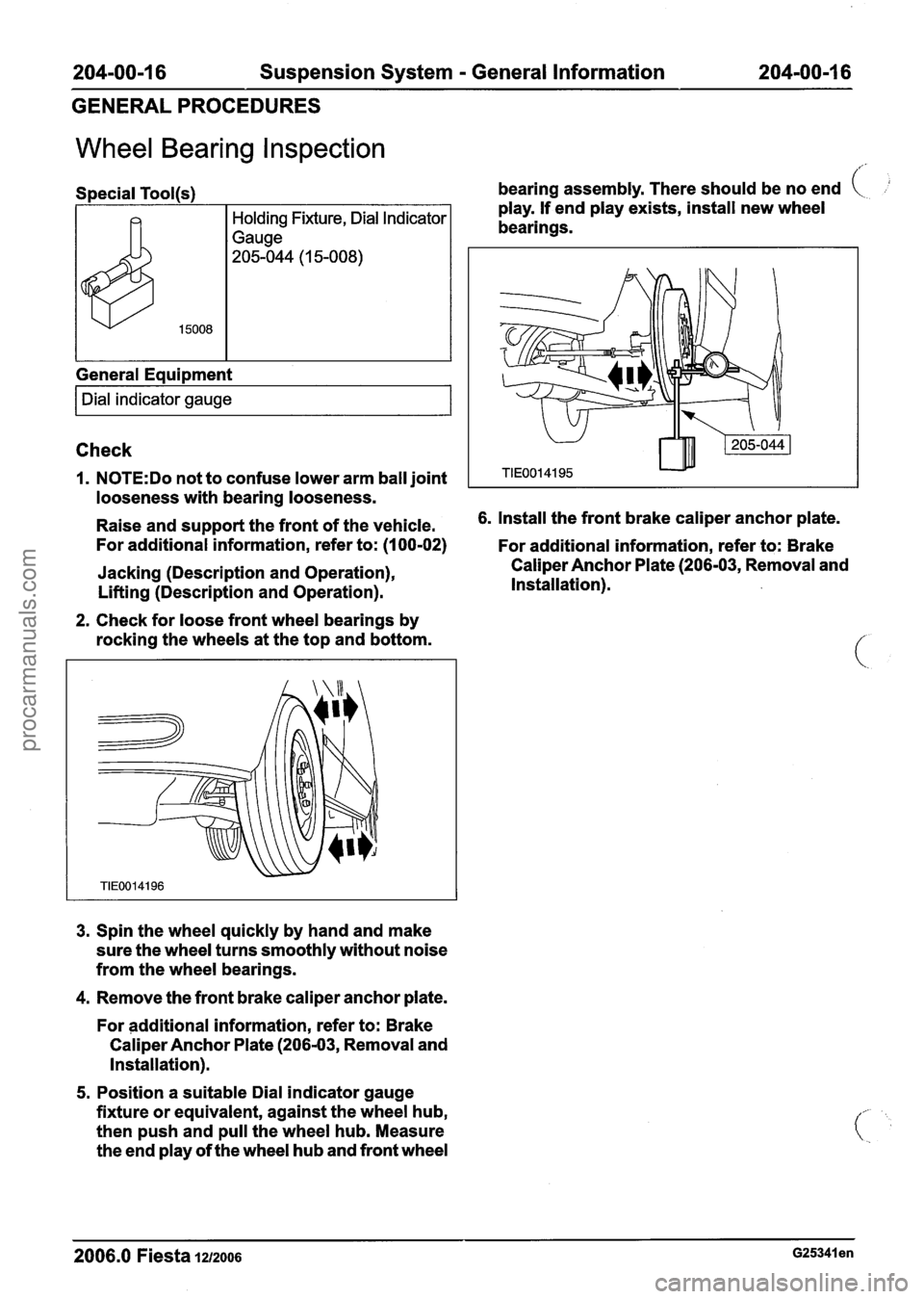
Wheel Bearing Inspection
Special Tool(s)
General Equipment
I Dial indicator gauge I
bearing assembly. There should be no end (
play. If end play exists, install new wheel
bearings.
Check
1. N0TE:Do not to confuse lower arm ball joint
looseness with bearing looseness.
Raise and support the front of the vehicle. 6.
Install the front brake caliper anchor plate.
For additional information, refer to: (I 00-02)
For additional information, refer to: Brake
Jacking (Description and Operation),
Lifting (Description and Operation).
2. Check for loose front wheel bearings by
rocking the wheels at the top and bottom.
3. Spin the wheel quickly by hand and make
sure the wheel turns smoothly without noise
from the wheel bearings.
4. Remove the front brake caliper anchor plate.
For additional information, refer to: Brake
Caliper Anchor Plate (206-03, Removal and
Installation).
5. Position a suitable Dial indicator gauge
fixture or equivalent, against the wheel hub,
then push and pull the wheel hub. Measure
the end play of the wheel hub and front wheel Caliper
Anchor Plate (206-03, Removal and
Installation).
2006.0 Fiesta 1212006 ~25341 en
procarmanuals.com
Page 107 of 1226
204-01 -9 Front Suspension 204-0 I -9
REMOVAL AND INSTALLATION
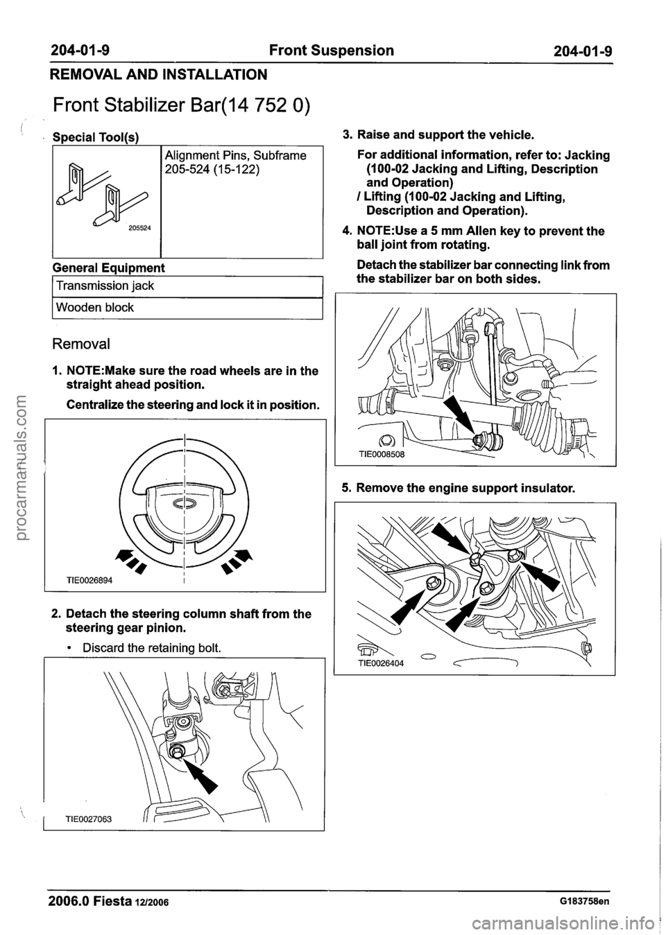
Front Stabilizer Bar(l4 752 0)
i , Special Tool(s1
General Equipment
205524
I Transmission jack 1
Alignment Pins, Subframe
205-524 (1 5-1 22)
I Wooden block I
Removal
1. N0TE:Make sure the road wheels are in the
straight ahead position.
Centralize the steering and lock
it in position.
2. Detach the steering column shaft from the
steering gear pinion.
Discard the retaining bolt.
3. Raise and support the vehicle.
For additional information, refer to: Jacking
(100-02 Jacking and Lifting, Description
and Operation)
I Lifting (1 00-02 Jacking and Lifting,
Description and Operation).
4. N0TE:Use a 5 mm Allen key to prevent the
ball joint from rotating.
Detach the stabilizer bar connecting link from
the stabilizer bar on both sides.
5. Remove the engine support insulator.
2006.0 Fiesta 1212006 GI 83758en
procarmanuals.com
Page 130 of 1226
204-0218 Rear Suspension 204-02-8
REMOVAL AND INSTALLATION
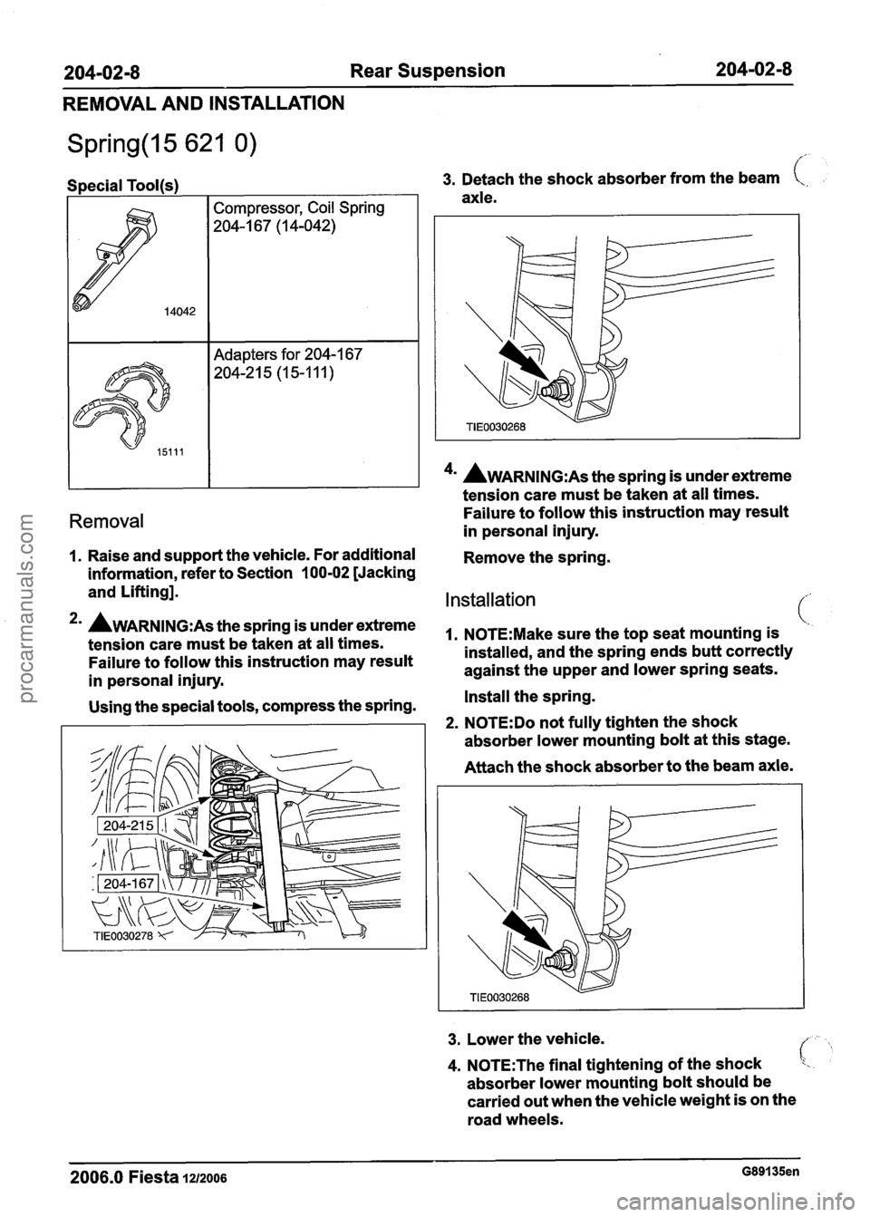
Special Tool(s) I I 3. Detach the shock absorber from the beam t,.
axle.
I I 1 4u AWARNING:A~ the spring is under extreme
tension care must
be taken at all times.
Removal Failure to follow this instruction may result
in personal injury.
1. Raise and support the vehicle. For additional
Remove the spring.
information, refer to Section
100-02 [Jacking
and Lifting].
Installation
2mA~~~~~~~:~~the~~ringis~nderextreme ~~~~~~:~~~~~~~~t~~t~~~~~tmo~~t~n~i~ (.
tension care must be taken at all times.
Failure to follow this instruction may result installed,
and the spring ends butt correctly
against the upper and lower spring seats.
in personal injury.
Using the special tools, compress the spring. Install
the spring.
2. N0TE:Do not fully tighten the shock
absorber lower mounting bolt at this stage.
Attach the shock absorber to the beam axle.
3. Lower the vehicle.
4. N0TE:The final tightening of the shock
absorber lower mounting bolt should be
carried out when the vehicle weight is on the
road wheels.
2006.0 Fiesta 1212006 G89135en
procarmanuals.com
Page 142 of 1226
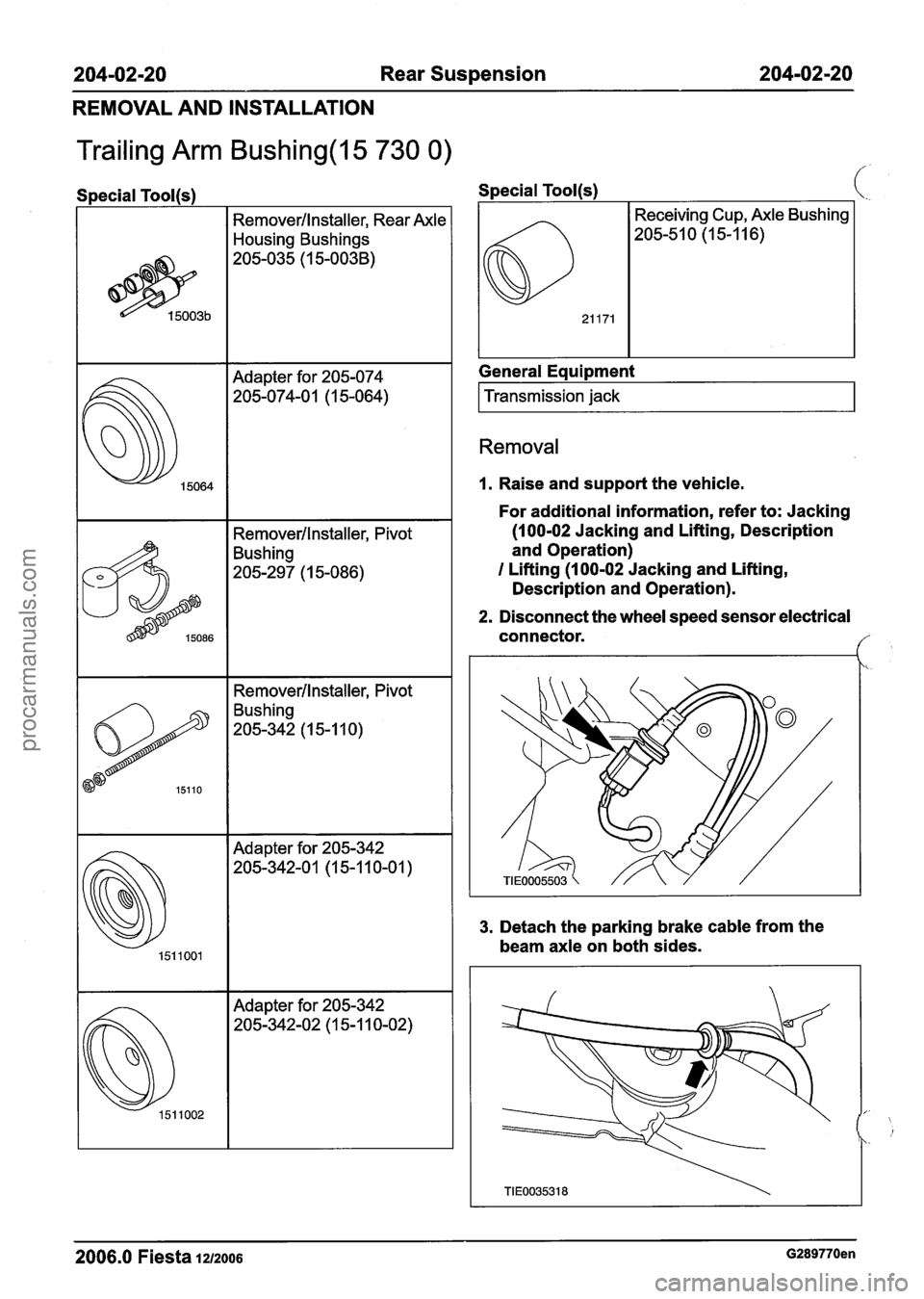
204-02-20 Rear Suspension 204-02-20
REMOVAL AND INSTALLATION
Trailing Arm Bushing(l5 730 0) ,
I
Remover/lnstaller, Rear Axle
Housing Bushings
Remover/lnstaller, Pivot
Bushing
205-297 (1 5-086)
15064
-- -
I Remover/lnstaller, Pivot
Adapter for
205-074
205-074-0 1 (1 5-064)
15110
Special Tool(s) ,
Bushing
205-342 (1 5-1 1 0)
151 1002
General Eaui~ment
Adapter for 205-342
205-342-02 (1 5-1 10-02)
I Transmission jack I
Removal
I. Raise and support the vehicle.
For additional information, refer to: Jacking
(100-02 Jacking and Lifting, Description
and Operation)
I Lifting (100-02 Jacking and Lifting,
Description and Operation).
2. Disconnect the wheel speed sensor electrical
connector.
f
3. Detach the parking brake cable from the
beam axle on both sides.
2006.0 Fiesta 1212006 G289770en
procarmanuals.com
Page 152 of 1226
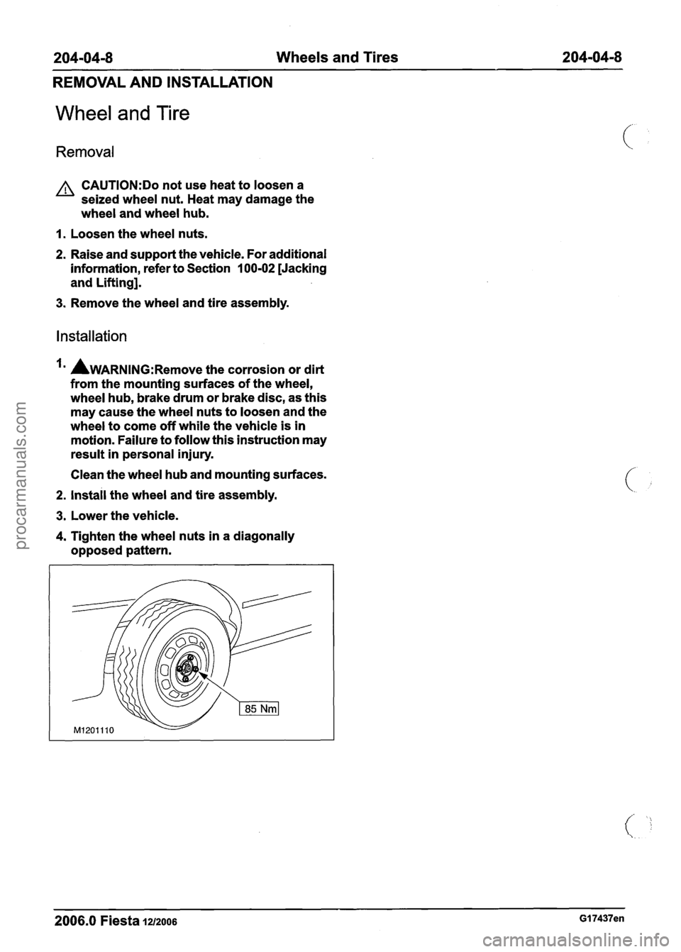
204-04-8 Wheels and Tires 204-04-8
REMOVAL AND INSTALLATION
Wheel and Tire
Removal
A CAUTI0N:Do not use heat to loosen a
seized wheel nut. Heat may damage the
wheel and wheel hub.
I. Loosen the wheel nuts.
2. Raise and support the vehicle. For additional
information, refer to Section
100-02 [Jacking
and Lifting].
3. Remove the wheel and tire assembly.
Installation
AWARNING:R~~~~~ the corrosion or dirt
from the mounting surfaces of the wheel,
wheel hub, brake drum or brake disc, as this
may cause the wheel nuts to loosen and the
wheel to come off while the vehicle is in
motion. Failure to follow this instruction may
result in personal injury.
Clean the wheel hub and mounting surfaces.
2. install the wheel and tire assembly.
3. Lower the vehicle.
4. Tighten the wheel nuts in a diagonally
opposed pattern.
2006.0 Fiesta 1212006 GI 7437en
procarmanuals.com
Page 202 of 1226
Brake System - General Information
DIAGNOSIS AND TESTING
evidence of a brake concern. Check for the brake
warning indicator illumination and the fluid level in
the master cylinder reservoir.
Normal Conditions
The following conditions are considered normal
and are not indications that the brake master
cylinder is in need of service.
- Modern brake systems are not designed to
produce as hard a pedal effort as in the past.
Complaints of light pedal efforts should be
compared to pedal efforts of another vehicle, of
the same model and year.
- During normal operation of the brake the fluid
level in the reservoir will rise during brake
application and fall during release. The net fluid
level
(i.e., after brake application and release)
will remain unchanged.
- A trace of brake fluid will exists on the brake
booster shell below the master cylinder
mounting flange. This results from the normal
lubricating action of the master cylinder bore
end seal.
- The fluid level will fall with brake shoe and lining
wear.
Abnormal Conditions
N0TE:Prior to performing any diagnosis, make
sure the brake system warning indicator is
functional.
Changes in brake pedal feel or travel are indicators
that something could be wrong with the braking system. The diagnostic procedure and techniques
use brake pedal feel, warning indicator illumination
and low brake fluid level as indicators in diagnosing
braking system concerns. The following conditions
are considered abnormal and indicate that the
brake master cylinder is in need of service.
- The brake pedal effort is excessive. This may
be caused by a bind or obstruction in the pedal
.
or linkage, clogged fluid control valve or ( ' insufficient booster vacuum.
- The rear brakes lock up during light pedal force.
This may be caused by incorrect tire pressures,
grease or fluid on the brake shoes and linings,
damaged brake shoes and linings, incorrectly
adjusted parking brake, or damaged or
contaminated brake pressure control valves.
- The brake pedal effort is erratic. This condition
could be caused by a brake booster malfunction,
extreme caliper piston knock back or incorrectly
installed brake shoes and linings.
- The brake warning indicator is ON. This may
be caused by low fluid level, ignition wire routing
too close to the fluid level indicator assembly,
or float assembly damage.
Bypass Condition Test
1. Check the fluid in brake master cylinder. Fill the
brake master cylinder reservoir if low or empty.
2. Observe the fluid level in the brake master
cylinder reservoir. If after several brake
applications, the fluid level remains the same,
measure the wheel turning torque required to
rotate the wheels with the brakes applied as
follows:
Place the transaxle in NEUTRAL and raise and
support the vehicle. REFER to: (1 00-02 Jacking
and Lifting)
Jacking (Description and Operation),
Lifting (Description and Operation).
Apply the brakes with a minimum of 445 N (100
Ib) and hold for approximately 15 seconds. With
the brakes still applied, exert a torque on the front
wheels of 10.1 Nm (75
1b.R). If either wheel rotates,
install a new brake master cylinder. REFER to:
(206-06 Hydraulic Brake Actuation)
- The brake pedal goes down fast. This could be Brake Master Cylinder - RHD (Removal and
caused by an external or internal leak. Installation),
- The brake
pedal eases down slowly. This could Brake Master Cylinder - LHD
(Removal and
be caused by an external or internal leak. Installation).
- The
brake pedal is low and or feels spongy. This
condition may be caused by no fluid in the brake
Non-Pressure Leaks master cylinder reservoir, reservoir cap vent
holes clogged or air in the hydraulic system.
Any empty brake master cylinder reservoir
condition may be caused by two types of
non-pressure external leaks.
2006.0 Fiesta 1212006
procarmanuals.com
Page 247 of 1226
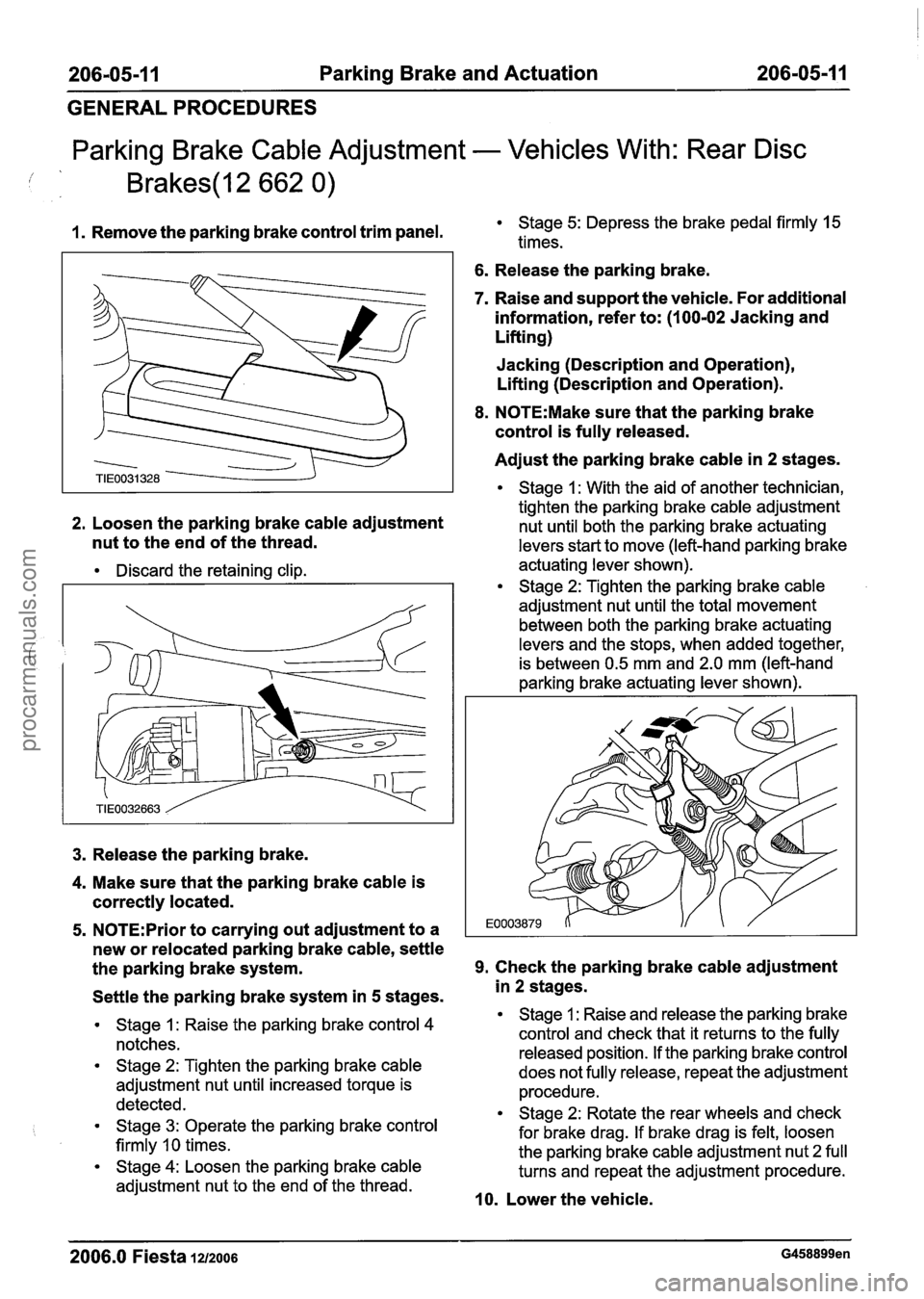
206-05-1 1 Parking Brake and Actuation 206-05-1 1
GENERAL PROCEDURES
Parking Brake Cable Adjustment - Vehicles With: Rear Disc
1. Remove the parking brake control trim panel. Stage 5: Depress the brake pedal firmly 15
times.
6. Release the parking brake.
7. Raise and support the vehicle. For additional
information, refer to: (1
00-02 Jacking and
Lifting)
Jacking (Description and Operation),
Lifting (Description and Operation).
8. N0TE:Make sure that the parking brake
control is fully released.
Adjust the parking brake cable in
2 stages.
Stage 1 : With the aid of another technician,
tighten the parking brake cable adjustment
2.
Loosen the parking brake cable adjustment nut until both the parking brake actuating
nut to the end of the thread. levers start to move (left-hand parking brake
Discard the retaining clip. actuating lever
shown). Stage 2: Tighten the parking brake cable
adjustment nut until the total movement
between both the parking brake actuating
levers and the stops, when added together,
is between 0.5 mm and 2.0 mm (left-hand
parking brake actuating lever shown).
3. Release the parking brake.
4. Make sure that the parking brake cable is
correctly located.
5. N0TE:Prior to carrying out adjustment to a
new or relocated parking brake cable, settle
the parking brake system.
9. Check the parking brake cable adjustment
Settle the parking brake system in
5 stages.
Stage 1 : Raise the parking brake control 4
notches.
Stage 2: Tighten the parking brake cable
adjustment nut until increased torque is
detected.
Stage 3: Operate the parking brake control
firmly
10 times.
Stage 4: Loosen the parking brake cable
adjustment nut to the end of the thread.
in 2 stages.
Stage 1 : Raise and release the parking brake
control and check that it returns to the fully
released position. If the parking brake control
does not fully release, repeat the adjustment
procedure.
Stage 2: Rotate the rear wheels and check
for brake drag. If brake drag is felt, loosen
the parking brake cable adjustment nut 2 full
turns and repeat the adjustment procedure.
10. Lower the vehicle.
2006.0 Fiesta 1212006 G458899en
procarmanuals.com
Page 249 of 1226
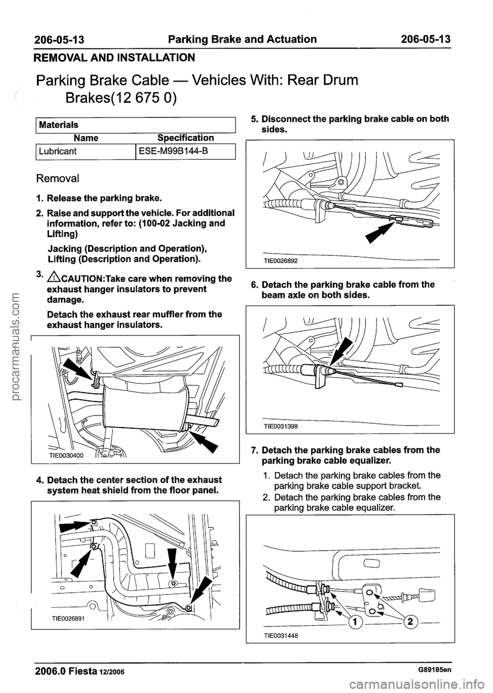
206-05-1 3 Parking Brake and Actuation 206-05-1 3
REMOVAL AND INSTALLATION
Parking Brake Cable - Vehicles With: Rear Drum
Brakes(l2 675 0)
I Lubricant I ESE-M99B144-B I
5. Disconnect the parking brake cable on both
Removal
Materials
I. Release the parking brake. sides.
2. Raise and support the vehicle. For additional
information, refer to: (100-02 Jacking and
Lifting) Name
Specification
Jacking (Description and Operation),
Lifting (Description and Operation).
3m ~CAUTION:T~~~ care when removing the 6, Detach the parking brake cable from the exhaust hanger insulators to prevent
damage. beam
axle on both sides.
Detach the exhaust rear muffler from the
exhaust hanger insulators.
4. Detach the center section of the exhaust
system heat shield from the floor panel. 7.
Detach the parking brake cables from the
parking brake cable equalizer. 1. Detach the parking brake cables from the
parking brake cable support bracket.
2. Detach the parking brake cables from the
parking brake cable equalizer.
2006.0 Fiesta 1212006 G89185en
procarmanuals.com
Page 251 of 1226
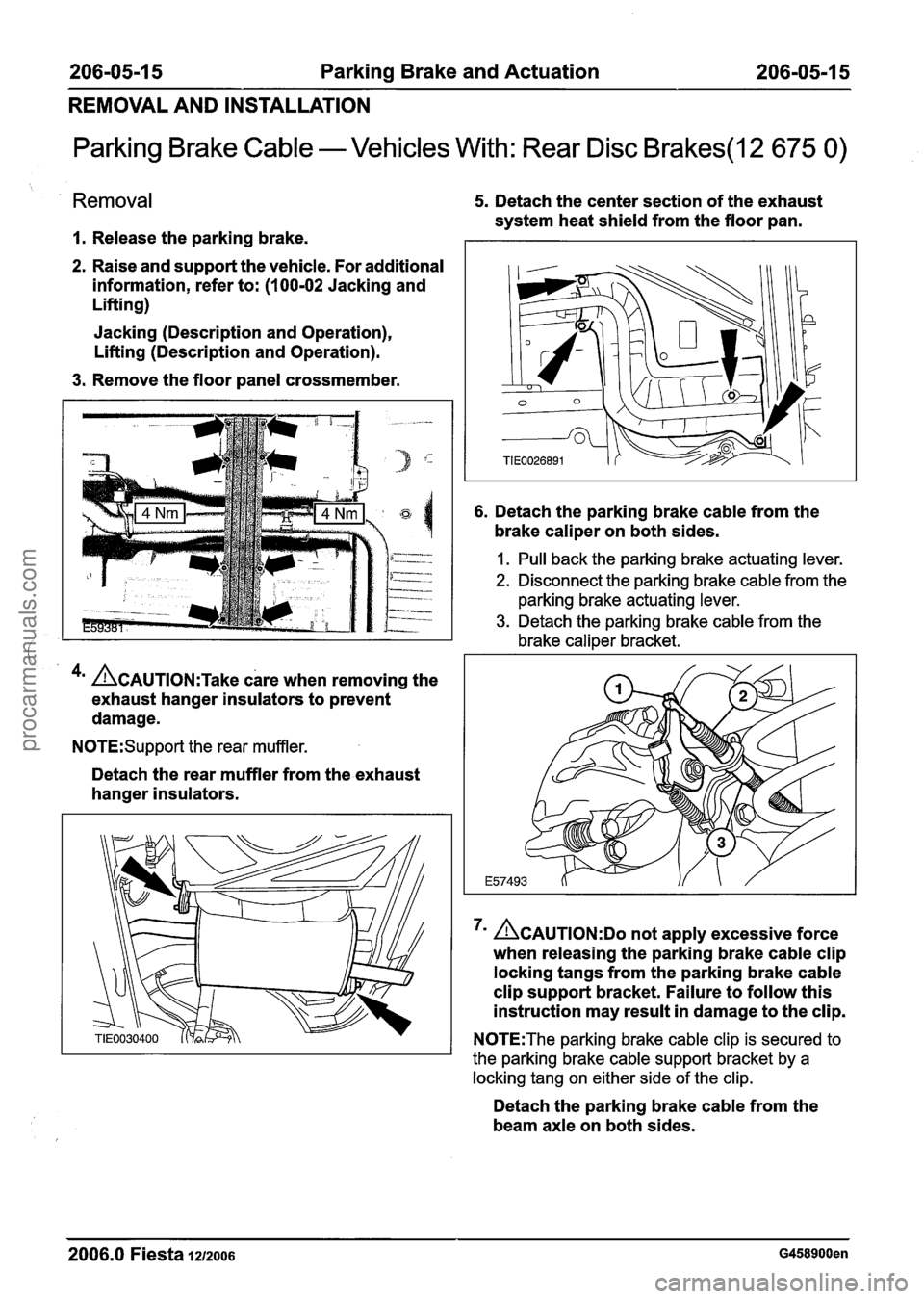
206-05-1 5 Parking Brake and Actuation 206-05-1 5
REMOVAL AND INSTALLATION
Parking Brake Cable - Vehicles With: Rear Disc Brakes(l2 675 0)
Removal
I. Release the parking brake.
2. Raise and support the vehicle. For additional
information, refer to:
(1 00-02 Jacking and
Lifting)
Jacking (Description and Operation),
Lifting (Description and Operation).
3. Remove the floor panel crossmember.
4m ACAUTION:T~~~ care when removing the
exhaust hanger insulators to prevent
damage.
N0TE:Support the rear muffler.
Detach the rear muffler from the exhaust
hanger insulators.
5. Detach the center section of the exhaust
system heat shield from the floor pan.
6. Detach the parking brake cable from the
brake caliper on both sides.
I. Pull back the parking brake actuating lever.
2. Disconnect the parking brake cable from the
parking brake actuating lever.
3. Detach the parking brake cable from the
brake caliper bracket.
ACAUTION:DO not apply excessive force
when releasing the parking brake cable clip
locking tangs from the parking brake cable
clip support bracket. Failure to follow this
instruction may result in damage to the clip.
N0TE:The parking brake cable clip is secured to
the parking brake cable support bracket by a
locking tang on either side of the clip.
Detach the parking brake cable from the
beam axle on both sides.
2006.0 Fiesta 1212006 G458900en
procarmanuals.com