jacking FORD FIESTA 2007 Owners Manual
[x] Cancel search | Manufacturer: FORD, Model Year: 2007, Model line: FIESTA, Model: FORD FIESTA 2007Pages: 1226, PDF Size: 61.26 MB
Page 1112 of 1226
308-03-22 Manual Transmission/Transaxle 308-03-22
IN-VEHICLE REPAIR
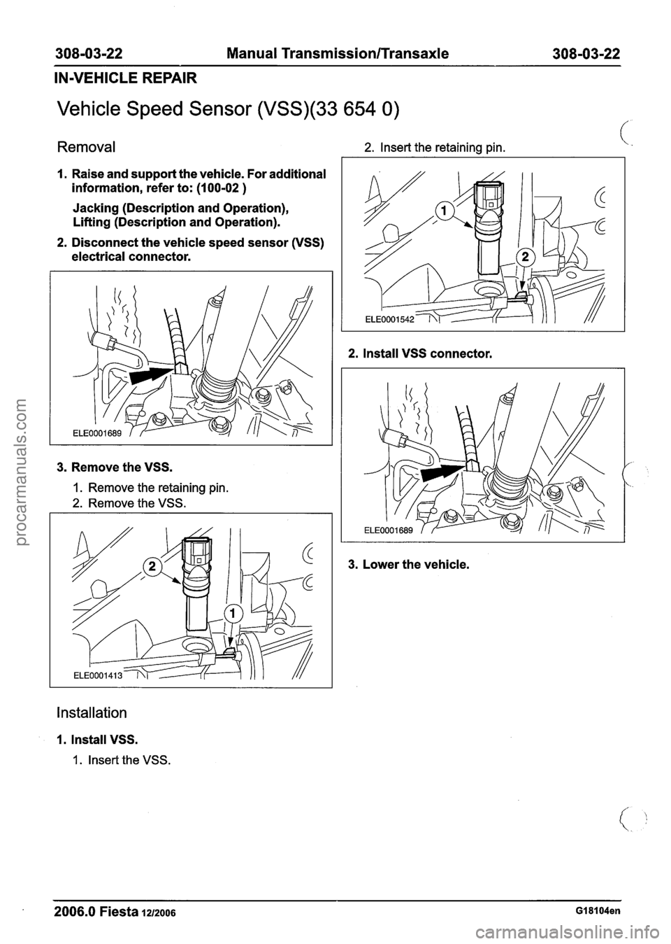
Vehicle Speed Sensor (VSS)(33 654 0)
Removal 2. Insert the retaining pin.
I. Raise and support the vehicle. For additional
information, refer to:
(1 00-02 )
Jacking (Description and Operation),
Lifting (Description and Operation).
2. Disconnect the vehicle speed sensor (VSS)
electrical connector.
3. Remove the VSS.
I. Remove the retaining pin.
2. Remove the VSS.
2. Install VSS connector.
3. Lower the vehicle.
Installation
1. Install VSS.
1. Insert the VSS.
2006.0 Fiesta iuzoos GI 81 04en
procarmanuals.com
Page 1123 of 1226
308-03-33 Manual Transmission/Transaxle 308-03-33
REMOVAL
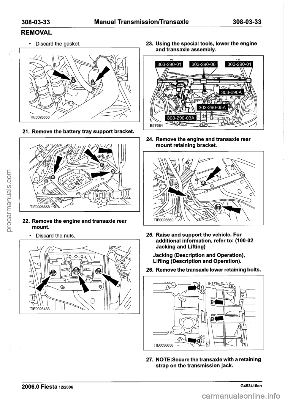
Discard the gasket.
,
23. Using the special tools, lower the engine
and transaxle assembly.
21. Remove the battery tray support bracket.
24. Remove the engine and transaxle rear
mount retaining bracket.
22. Remove the engine and transaxle rear
mount.
Discard the nuts. 25. Raise and support the vehicle. For
additional information, refer to:
(1 00-02
Jacking and Lifting)
Jacking (Description and Operation),
Lifting (Description and Operation).
26. Remove the transaxle lower retaining bolts.
27. N0TE:Secure the transaxle with a retaining
strap on the transmission jack.
2006.0 Fiesta 1212006 G453416en
procarmanuals.com
Page 1154 of 1226
308-03-64 Manual Transmission/Transaxle 308-03-64
INSTALLATION
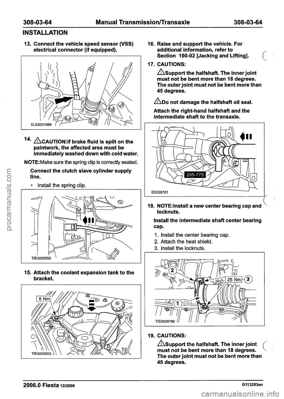
13. Connect the vehicle speed sensor (VSS) 16. Raise and support the vehicle. For
electrical connector (if equipped). additional information, refer to
Section 100-02 [Jacking and Lifting].
17. CAUTIONS:
Asupport the halfshaft. The inner joint
must not be bent more than 18 degrees.
The outer joint must not be bent more than
45 degrees.
ADO not damage the halfshaft oil seal.
Attach the right-hand halfshaft and the
intermediate shaft to the transaxle.
14' ACAUTION:~~ brake fluid is spilt on the
paintwork, the affected area must be
immediately washed down with cold water.
N0TE:Make sure the spring clip is correctly seated.
Connect the clutch slave cylinder supply
line.
Install the spring clip.
15. Attach the coolant expansion tank to the
bracket. 18.
N0TE:lnstall a
new center bearing cap and
locknuts.
Install the intermediate shaft center bearing
cap.
I. Install the center bearing cap.
2. Attach the heat shield.
3. Install the locknuts.
19. CAUTIONS:
Asupport the halfshaft. The inner joint
must not be bent more than 18 degrees.
The outer joint must not be bent more than
45 degrees.
2006.0 Fiesta 1212006 GI I 3293en
procarmanuals.com
Page 1161 of 1226
308-03-71 Manual Transmission/Transaxle 308-03-71
INSTALLATION
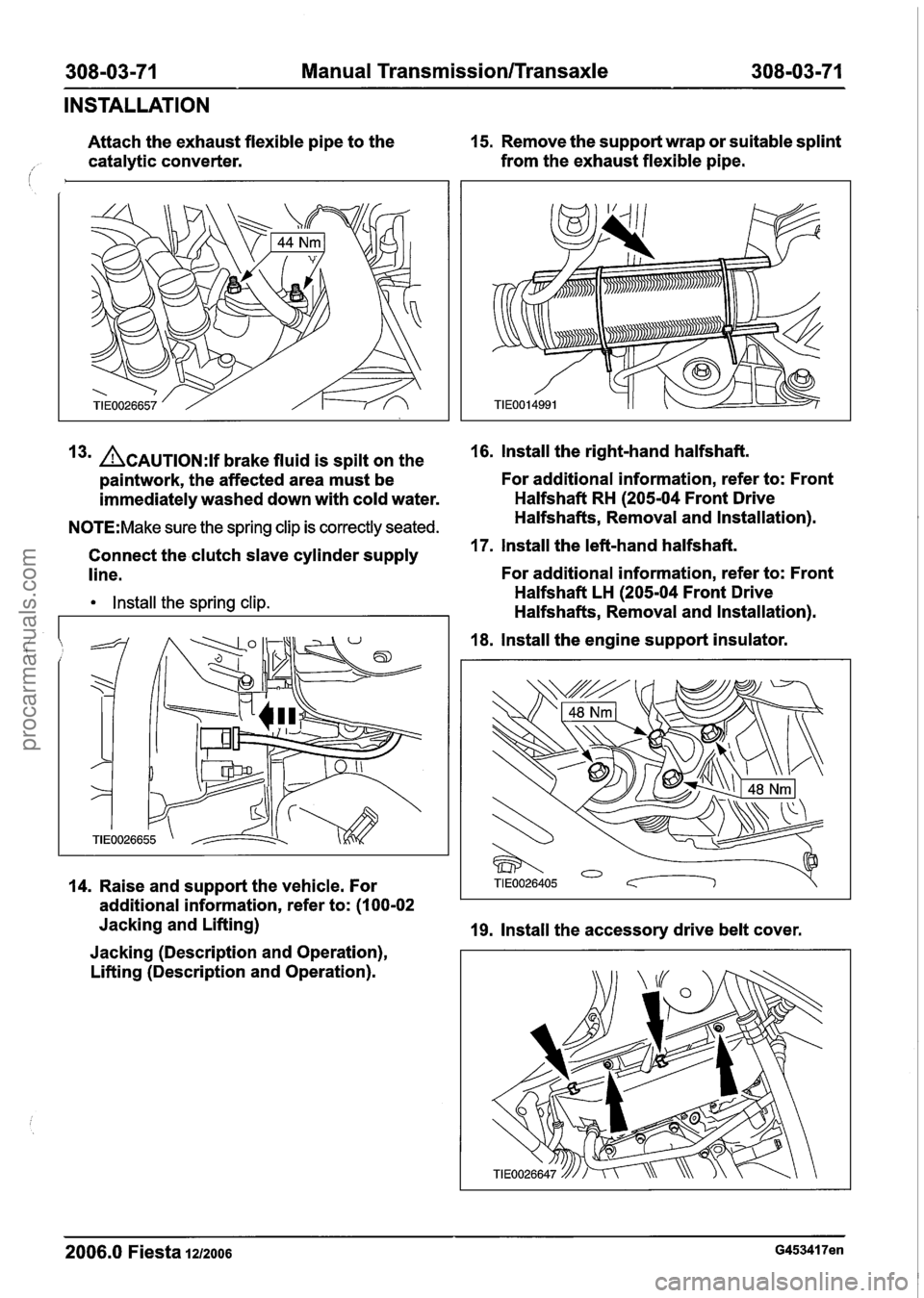
Attach the exhaust flexible pipe to the 15.
Remove the support wrap or suitable splint
catalytic converter. from
the exhaust flexible pipe.
i
3m ACAUTION:~~ brake fluid is spilt on the 16. lnstall the right-hand halfshaft.
paintwork, the affected area must be For additional information,
refer to: Front
immediately washed down with cold water. Halfshaft
RH (205-04 Front Drive
N0TE:Make sure the spring clip is correctly seated. Halfshafts, Removal and Installation).
Connect the clutch slave cylinder supply
17. lnstall the left-hand halfshaft.
line. For additional information,
refer to: Front
lnstall the spring clip. Halfshaft LH (205-04 Front Drive
Halfshafts, Removal and Installation).
18. lnstall the engine support insulator.
14. Raise and support the vehicle. For
additional information, refer to: (I
00-02
Jacking and Lifting)
19. Install the accessory drive belt cover.
Jacking (Description and Operation),
Lifting (Description and Operation).
2006.0 Fiesta 1212006 G453417en
procarmanuals.com
Page 1172 of 1226
Manual Transmission/Transaxle External
308-06-8 Controls 308-06-8
REMOVAL AND INSTALLATION
Gearshift Cables(l6 575 0)
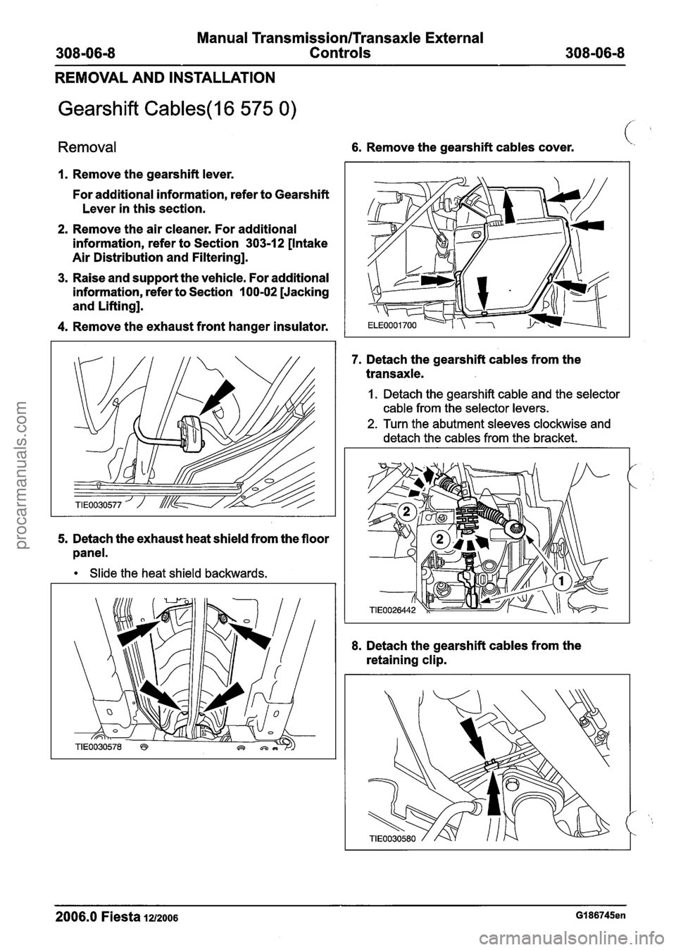
Removal 6. Remove the gearshift cables cover.
I. Remove the gearshift lever.
For additional information, refer to Gearshift
Lever in this section.
2. Remove the air cleaner. For additional
information, refer to Section
303-12 [Intake
Air Distribution and Filtering].
3. Raise and support the vehicle. For additional
information, refer to Section
100-02 [Jacking
and Lifting].
4. Remove the exhaust front hanger insulator.
5. Detach the exhaust heat shield from the floor
panel.
Slide the heat shield backwards.
7. Detach the gearshift cables from the
transaxle.
I. Detach the gearshift cable and the selector
cable from the selector levers.
2. Turn the abutment sleeves clockwise and
detach the cables from the bracket.
8. Detach the gearshift cables from the
retaining clip.
2006.0 Fiesta 1212006 GI 86745en
procarmanuals.com
Page 1174 of 1226
Manual Transmission/Transaxle External
308-06-1 0 Controls 308-06-1 0
REMOVAL AND INSTALLATION
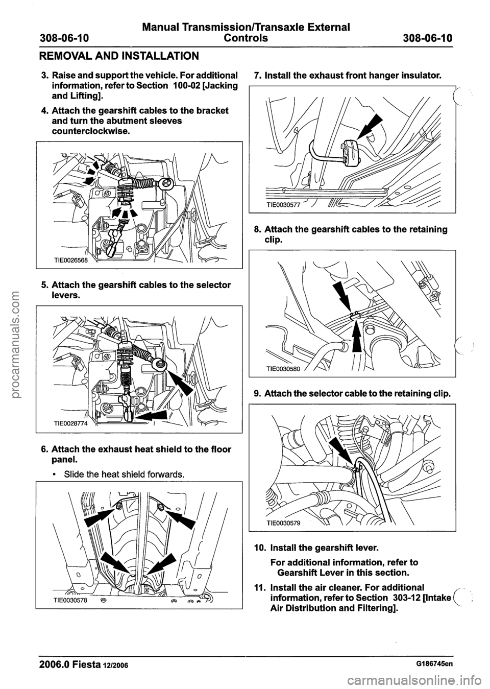
3. Raise and support the vehicle. For additional 7. Install the exhaust front hanger insulator.
information, refer to Section
100-02 [Jacking
and Lifting].
4. Attach the gearshift cables to the bracket
and turn the abutment sleeves
counterclockwise.
6. Attach the exhaust heat shield to the floor
panel.
Slide the heat shield forwards. 8.
Attach
the gearshift cables to the retaining
clip.
9. Attach the selector cable to the retaining clip.
10. Install the gearshift lever.
For additional information, refer to
Gearshift Lever in this section.
11. Install the air cleaner. For additional
information, refer to Section
303-12 [Intake (
Air Distribution and Filtering].
2006.0 Fiesta 1212006 GI 86745en
procarmanuals.com
Page 1182 of 1226

309-00-6 Exhaust System 309-00-6
REMOVAL AND INSTALLATION
Catalytic Converter - 2.OL Duratec-HE (M14)
/'
Materials Support
the exhaust flexible pipe with a (,
support wrap or splint.
Name Specification
1 Grease I SA-M 1 C9107-A I --
N0TE:lf installing a new catalytic converter to the
original exhaust system, a new muffler and tailpipe
assembly must also be installed.
1. Raise and support the vehicle. For additional
information, refer to:
(1 00-02 Jacking and
Lifting)
Jacking (Description and Operation),
Lifting (Description and Operation).
*' CAUTION:^^^^ bending of the exhaust
flexible pipe may cause damage resulting in 3. Remove the components in the order failure.
indicated in the following illustration(s) and
table(s).
Item Description Item Description
2006.0 Fiesta 1212006 G453448en
2
3
See Removal Detail
See Installation Detail
1
Catalytic converter monitor sensor
electrical connector
Catalytic converter monitor sensor
Exhaust hanger insulator
4 Catalytic converter to exhaust flexible pipe
retaining nuts
procarmanuals.com
Page 1184 of 1226
309=00=8 Exhaust System 309m00m8
REMOVAL AND INSTALLATION
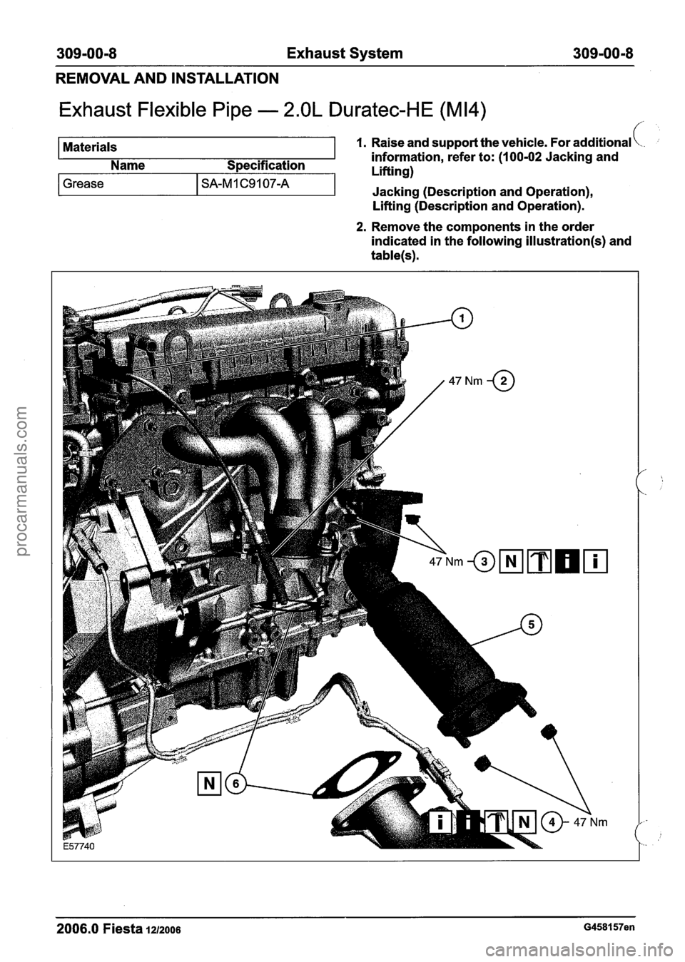
Exhaust Flexible Pipe - 2.OL Duratec-HE (M14)
Materials 1. Raise and support the vehicle. For additional \.. ;
information, refer to: (I 00-02 Jacking and
Name Specification
I 1 Liftinn)
Lifting (Description and Operation).
Grease I SA-M 1 C9 1 07-A
2. Remove the components in the order
indicated in the following
illustration(s) and
table(s).
-I
2006.0 Fiesta 1212006 G458157en
Jacking (Description and Operation),
procarmanuals.com
Page 1204 of 1226
31 0-01 -6 Fuel Tank and Lines 31 0-01 -6
REMOVAL AND INSTALLATION
Fuel Tank(23 554 0)
Special Tool(s)
I I Wrench, Sender Unit, Fuel
General Equipment
I Transmission jack I
Removal
All vehicles
WARNINGS:
A Do not smoke or carry lighted tobacco or
open flame of any type when working on
or near fuel related components. Highly
flammable vapors are always present and
may ignite. Failure to follow these
instructions may result in personal injury.
A This procedure involves fuel handling. Be
prepared for fuel spillage at all times and
always observe fuel handling precautions.
Failure to follow these instructions may
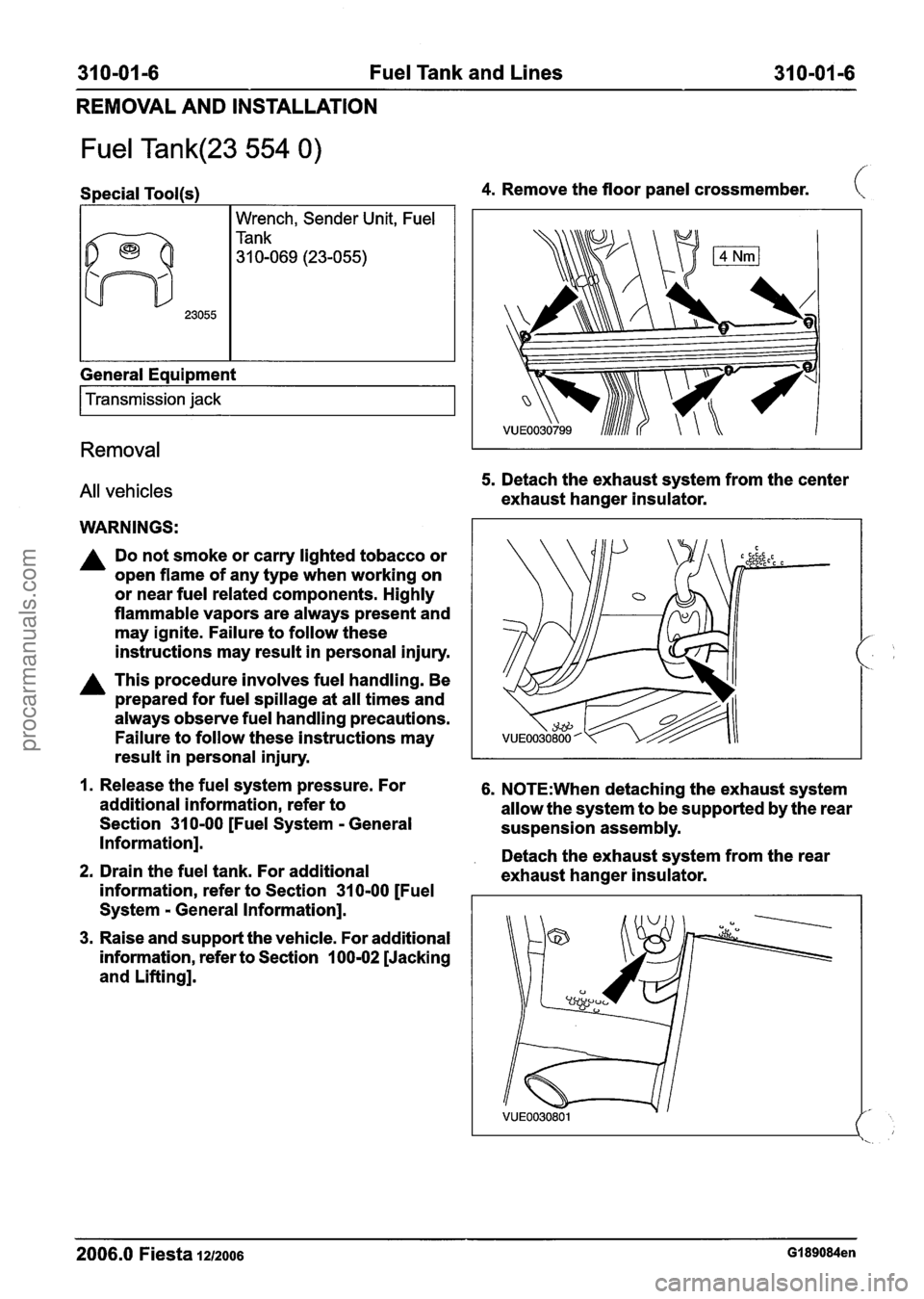
4. Remove the floor panel crossmember. (
5. Detach the exhaust system from the center
exhaust hanger insulator.
result in personal injury.
I
1. Release the fuel system pressure. For 6. N0TE:When detaching the exhaust system
additional information, refer to
allow the system to be supported by the rear
Section
31 0-00 [Fuel System - General
suspension assembly.
Information].
. Detach the exhaust system from the rear 2. Drain the fuel tank. For additional
exhaust hanger insulator.
information, refer to Section
31 0-00 [Fuel
System
- General Information].
3. Raise and support the vehicle. For additional
information, refer to Section
100-02 [Jacking
and Lifting].
2006.0 Fiesta 1212006 GI 89084en
procarmanuals.com
Page 1210 of 1226
31 0-01 -1 2 Fuel Tank and Lines 31 0-01-12
REMOVAL AND INSTALLATION
Fuel Tank Filler Pipe(23 572 0)
Removal
WARNINGS:
A Do not smoke or carry lighted tobacco or
open flame of any type when working on
or near any fuel related components.
Highly flammable vapours are always
present and can ignite. Failure to follow
these instructions may result in personal
injury.
A This procedure involves fuel handling. Be
prepared for fuel spillage at all times and
always observe fuel handling precautions.
Failure to follow these instructions may
result in personal injury.
I. Disconnect the battery ground cable. For
additional information, refer to
Section
41 4-01 [Battery, Mounting and
Cables].
2. Drain the fuel tank. For additional
information, refer to Section
31 0-00 [Fuel
System
- General Information].
3. Raise and support the vehicle. For additional
information, refer to Section
100-02 [Jacking
and Lifting].
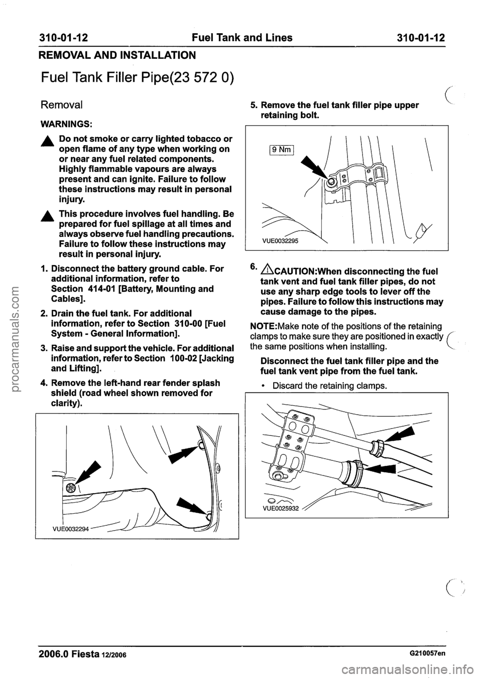
4. Remove the left-hand rear fender splash
shield (road wheel shown removed for
clarity).
5. Remove the fuel tank filler pipe upper (.
retaining bolt.
'' &AUTION:W~~~ disconnecting the fuel
tank vent and fuel tank filler pipes, do not
use any sharp edge tools to lever off the
pipes. Failure to follow this instructions may
cause damage to the pipes.
N0TE:Make note of the positions of the retaining
clamps to make sure they are positioned in exactly
the same positions when installing.
Disconnect the fuel tank filler pipe and the
fuel tank vent pipe from the fuel tank.
Discard the retaining clamps.
2006.0 Fiesta 1212006 G210057en
procarmanuals.com