FORD FIESTA 2007 Workshop Manual
Manufacturer: FORD, Model Year: 2007, Model line: FIESTA, Model: FORD FIESTA 2007Pages: 1226, PDF Size: 61.26 MB
Page 201 of 1226

206-00-29 Brake System - General Information 206-00-29
DIAGNOSIS AND TESTING
and repair the external leak. If the fluid level drops
and no external leak can be found, check for a
brake master cylinder bore end seal leak.
Brake System Check
Brake Pedal Reserve Check
Where a low brake pedal or the feel of a
bottomed-out condition exists, check for brake
pedal reserve.
1. Operate the engine at idle with the transaxle in
NEUTRAL.
2. Apply the brake pedal lightly three or four times.
3. Allow 15 seconds for vacuum to replenish the
brake booster.
N0TE:This increased resistance may feel like
something has bottomed out.
4. Apply the brake pedal until it stops moving
downward or an increased resistance to the
pedal travel occurs.
5. Hold the brake pedal in the applied position and
raise the engine speed to approximately 2000
rpm.
N0TE:The additional movement of the brake pedal
is the result of the increased engine intake manifold
vacuum which exerts more force on the brake
booster during engine rundown. This means that
additional stroke is available in the brake master
cylinder and the brake system is not bottoming out.
6. Release the accelerator pedal and observe that
the brake pedal moves downward as the engine
returns to idle speed.
Brake Booster Functional Test
lnspect all hoses and connections. All unused
vacuum connectors should be capped. Hoses and
their connections should be correctly secured and
in good condition with no holes and no collapsed 2.
With the transaxle in NEUTRAL, stop the engine
and apply the parking brake. Apply the brake
pedal several times to exhaust all vacuum in
the system.
3. With the engine turned off and all vacuum in the
system exhausted, apply the brake pedal and hold it down. Start the engine. If the vacuum
system is operating, the brake pedal will tend
to move downward under constant foot
pressure. If no motion is felt, the vacuum
booster system is not functioning.
4. Remove the vacuum hose from the brake
booster.
Intake manifold vacuum should be
available at the brake booster end of the hose
with the engine at idle speed and the transaxle
in NEUTRAL. Make sure that all unused vacuum
outlets are correctly capped, hose connectors
are correctly secured and vacuum hoses are in
good condition. When it is established that
manifold vacuum is available to the brake
booster, connector the vacuum hose to the
brake booster and repeat Step
3. If no
downward movement of the brake pedal is felt,
install a new brake booster. REFER to: (206-07
Power Brake Actuation)
Brake Booster
- LHD (Removal and lnstallation),
Brake Booster
- RHD (Removal and lnstallation).
5. Operate the engine a minimum of 10 seconds
at fast idle. Stop the engine and let the vehicle
stand for
10 minutes. Then, apply the brake
pedal with approximately 89
N (20 lb) force. The
pedal feel (brake application) should be the
same as that noted with the engine operating.
If the brake pedal feels hard (no power assist),
install a new vacuum check valve and then
repeat the test. If the brake pedal still feels hard,
install a new brake booster. REFER to: (206-07
Power Brake Actuation)
Brake Booster
- LHD (Removal and Installation),
Brake Booster
- RHD e em oval and installation).
If the brake pedal movement feels spongy, bleed
the brake system. REFER to: (206-00 Brake
System
- General Information)
areas. Inspect the check valve on the brake booster Brake System Bleeding (General Procedures),
for damage. Brake
System Pressure Bleeding (General
Procedures).
Brake Booster Operation Check
Brake Master Cylinder
1. Check the hydraulic brake system for leaks or
low fluid. Usually,
the first and strongest indicator of anything
wrong with the braking system is a feeling through
the brake pedal. In diagnosing the condition of the
brake master cylinder, check pedal feel as
2006.0 Fiesta 1212006 G28494en I
i
procarmanuals.com
Page 202 of 1226
Brake System - General Information
DIAGNOSIS AND TESTING
evidence of a brake concern. Check for the brake
warning indicator illumination and the fluid level in
the master cylinder reservoir.
Normal Conditions
The following conditions are considered normal
and are not indications that the brake master
cylinder is in need of service.
- Modern brake systems are not designed to
produce as hard a pedal effort as in the past.
Complaints of light pedal efforts should be
compared to pedal efforts of another vehicle, of
the same model and year.
- During normal operation of the brake the fluid
level in the reservoir will rise during brake
application and fall during release. The net fluid
level
(i.e., after brake application and release)
will remain unchanged.
- A trace of brake fluid will exists on the brake
booster shell below the master cylinder
mounting flange. This results from the normal
lubricating action of the master cylinder bore
end seal.
- The fluid level will fall with brake shoe and lining
wear.
Abnormal Conditions
N0TE:Prior to performing any diagnosis, make
sure the brake system warning indicator is
functional.
Changes in brake pedal feel or travel are indicators
that something could be wrong with the braking system. The diagnostic procedure and techniques
use brake pedal feel, warning indicator illumination
and low brake fluid level as indicators in diagnosing
braking system concerns. The following conditions
are considered abnormal and indicate that the
brake master cylinder is in need of service.
- The brake pedal effort is excessive. This may
be caused by a bind or obstruction in the pedal
.
or linkage, clogged fluid control valve or ( ' insufficient booster vacuum.
- The rear brakes lock up during light pedal force.
This may be caused by incorrect tire pressures,
grease or fluid on the brake shoes and linings,
damaged brake shoes and linings, incorrectly
adjusted parking brake, or damaged or
contaminated brake pressure control valves.
- The brake pedal effort is erratic. This condition
could be caused by a brake booster malfunction,
extreme caliper piston knock back or incorrectly
installed brake shoes and linings.
- The brake warning indicator is ON. This may
be caused by low fluid level, ignition wire routing
too close to the fluid level indicator assembly,
or float assembly damage.
Bypass Condition Test
1. Check the fluid in brake master cylinder. Fill the
brake master cylinder reservoir if low or empty.
2. Observe the fluid level in the brake master
cylinder reservoir. If after several brake
applications, the fluid level remains the same,
measure the wheel turning torque required to
rotate the wheels with the brakes applied as
follows:
Place the transaxle in NEUTRAL and raise and
support the vehicle. REFER to: (1 00-02 Jacking
and Lifting)
Jacking (Description and Operation),
Lifting (Description and Operation).
Apply the brakes with a minimum of 445 N (100
Ib) and hold for approximately 15 seconds. With
the brakes still applied, exert a torque on the front
wheels of 10.1 Nm (75
1b.R). If either wheel rotates,
install a new brake master cylinder. REFER to:
(206-06 Hydraulic Brake Actuation)
- The brake pedal goes down fast. This could be Brake Master Cylinder - RHD (Removal and
caused by an external or internal leak. Installation),
- The brake
pedal eases down slowly. This could Brake Master Cylinder - LHD
(Removal and
be caused by an external or internal leak. Installation).
- The
brake pedal is low and or feels spongy. This
condition may be caused by no fluid in the brake
Non-Pressure Leaks master cylinder reservoir, reservoir cap vent
holes clogged or air in the hydraulic system.
Any empty brake master cylinder reservoir
condition may be caused by two types of
non-pressure external leaks.
2006.0 Fiesta 1212006
procarmanuals.com
Page 203 of 1226
206-00-31 Brake System - General Information 206-00-31
DIAGNOSIS AND TESTING
Type 1: An external leak may occur at the master
cylinder reservoir cap because of incorrect
( positioning of the gasket and cap. Reposition the
cap and gasket.
Type
2: An external leak may occur at the reservoir
mounting seals. Service such a leak by installing
new seals.
2006.0 Fiesta 1212006 G28494en
procarmanuals.com
Page 204 of 1226
206-00-32 Brake System - General Information 206-00-32
GENERAL PROCEDURES
Brake System Bleeding(l2 141 0) /'. ,
All Vehicles Repeat the procedure for the remaining brake
A WARNING:Brake fluid contains polyglycol lines.
ethers and polyglycols. Avoid contact with
General
Equipment
9m ACAUTION:M~~~ sure that the bleed nipple
the eyes. Wash hands thoroughly after
Vehicles with anti-lock brakes handling. If brake fluid contacts the eyes,
flush the eyes for
15 minutes with cold 10. N0TE:This step is only necessary when
running water. Get medical attention
if changing the brake fluid to remove the used
irritation persists.
If taken internally, drink brake
fluid from the hydraulic control unit
water and induce vomiting. Get medical (HCU).
Worldwide
Diagnostic System (WDS)
attention immediately. Failure to follow
Using WDS, bleed the brake system.
these instructions may result in personal'
injury.
CAUTI0N:If brake fluid is spilt on the
paintwork, the affected area must be
immediately washed down with cold water. cap
is installed after bleeding the brake
N0TE:Make sure that the vehicle is standing on a
level surface.
line(s). This will prevent corrosion to the
bleed nipple. Failure to follow this instruction
Bleeding may result in the bleed nipple becoming
seized.
N0TE:The system consists of separate circuits for
each front and diagonally opposite rear wheel.
Each circuit can be bled independently.
ACAUTION:T~~ brake fluid reservoir must
remain full with new, clean brake fluid at all
times during bleeding.
Install the bleed tube to the bleed nipple.
2. Immerse the end of the bleed tube in a bleed
jar containing a small quantity of approved
brake fluid.
3. Position the bleed jar base at least 300 mm
above the bleed nipple to maintain fluid
pressure and prevent air leaking past the
threads of the bleed nipple.
4. Loosen the bleed nipple by one-half turn.
5. Operate the brake pedal fully ipumping brake
fluid and air into the bleed jar) and allow the
brake pedal to return to the rest position.
6. Fill the brake fluid reservoir to the MAX mark.
7. Continue operating the brake pedal until
air-free fluid is being pumped into the bleed
jar.
8. With the brake pedal fully depressed tighten
the bleed nipple.
2006.0 Fiesta IZIZOO~ GI 7458en
procarmanuals.com
Page 205 of 1226
206-00-33 Brake System - General Information 206-00-33
GENERAL PROCEDURES
Brake System Pressure Bleeding(l2 141 0)
Bleeding
i General Equipment Vehicles with anti-lock brakes
All vehicles
Worldwide Diagnostic System (WDS)
Brakelclutch system pressure bleederlfiller
A WARNING: Brake fluid contains polyglycol
ethers and polyglycols. Avoid contact with
the eyes. Wash hands thoroughly after
handling. If brake fluid contacts the eyes,
flush the eyes for
15 minutes with cold
running water. Get medical attention if
irritation persists. If taken internally, drink
water and induce vomiting. Get medical
attention immediately. Failure to follow
these instructions may result in personal
injury.
4. N0TE:This ste.p is only necessary when
changing the brake fluid to remove the used
A CAUTI0N:If brake fluid is spilt on the
paintwork, the affected area must be
immediately washed down with cold water.
/
brake fluid from the hydraulic control unit
I N0TE:Make sure that the vehicle is standing on a
level surface.
N0TE:The system consists of separate circuits for
each front and diagonally opposite rear wheel.
Each circuit can be bled independently.
I. Fill the brake fluid reservoir to the MAX mark.
2. CAUTIONS:
AMake sure that the pressure within the
brake system does not exceed
1 bar.
n~ake sure that the pressure bleeding
equipment is filled with new brake fluid to
the correct specification.
Using the
brakelclutch system pressure
bleederlfiller, pressure bleed the system in
accordance with the manufacturer's
instructions.
3n ACAUTION:M~~~ sure that the bleed nipple
cap is installed after bleeding the brake
line(s). This will prevent corrosion to the
bleed nipple. Failure to follow this instruction
I may result in the bleed nipple becoming
seized.
Fill the brake fluid reservoir to the
MAX mark
as necessary. (HCU).
Using
WDS, bleed the brake system.
2006.0 Fiesta 1212006
procarmanuals.com
Page 206 of 1226

procarmanuals.com
Page 207 of 1226
206-02-1 Drum Brake 206-02-1
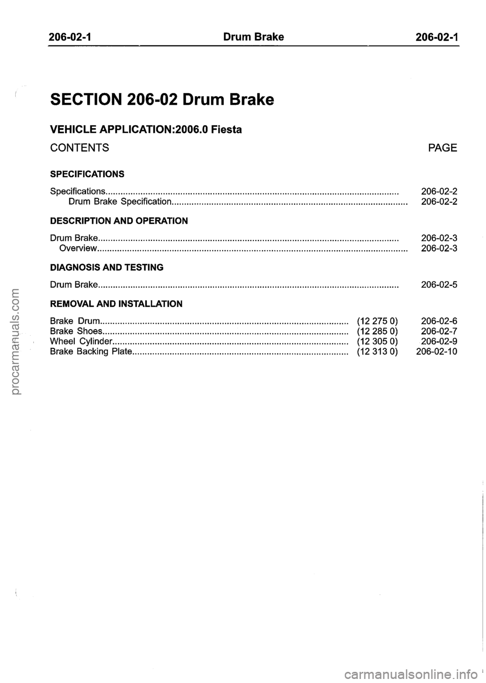
SECTION 206-02 Drum Brake
VEHICLE APPLICATION:2006.0 Fiesta
CONTENTS PAGE
SPECIFICATIONS
Specifications.. . . . . . . . . . . . . . . . . . . . . . . . . . . . . . . . . . . . . . . . . . . . . . . . . . . . . . . . . . . . . . . . . . . . . . . . . . . . . . . . . . . . . . . . . . . . . . . . . . . . . . . . . . . . . . . . . . . . . 206-02-2
Drum Brake Specification ........................................................................\
.................. 206-02-2
DESCRIPTION AND OPERATION
Drum Brake ........................................................................\
................................................. 206-02-3
Overview ........................................................................\
..................................................... 206-02-3
DIAGNOSIS AND TESTING
Drum Brake ........................................................................\
.................................................
REMOVAL AND INSTALLATION
Brake Drum ........................................................................\
............................ (122750) 206-02-6
Brake Shoes ..... .. . . . . .. . . .. .. .. . . .. . . .. . . .. . . . . . . . . . . . . . . . .. . . . . . . . . . . . . . . . . . . . . . . . (1 2 285 0)
206-02-7
( Wheel Cylinder ........................................................................\
.................. (12 305 0) 206-02-9
Brake Backing Plate .... ........................................................................\
........... (12 31 3 0)
206-02-1 0
procarmanuals.com
Page 208 of 1226
206-02-2 Drum Brake 206-02-2
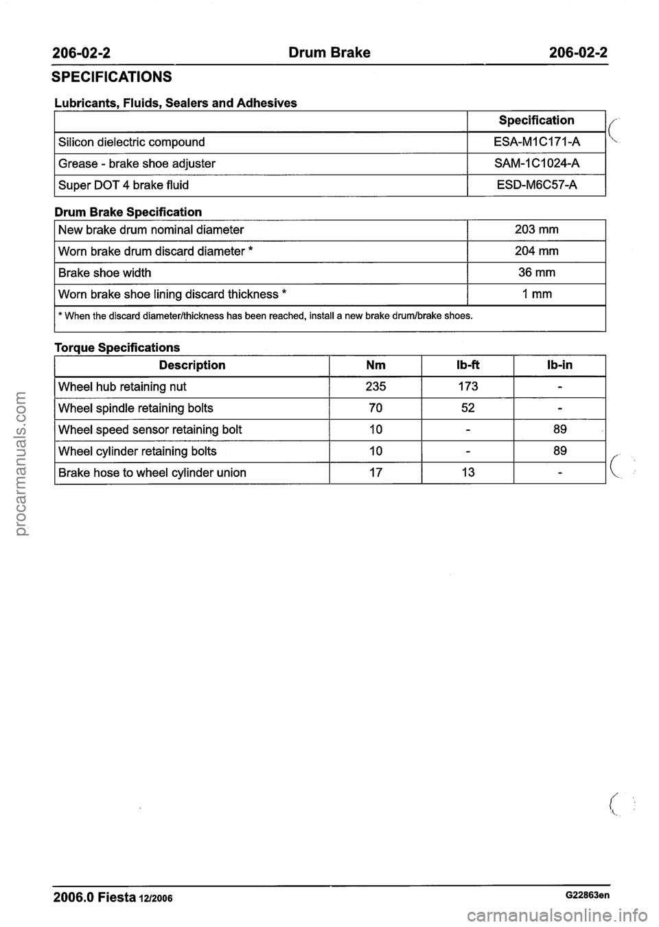
SPECIFICATIONS
Lubricants, Fluids, Sealers and Adhesives
I Grease - brake shoe adjuster I SAM-1C1024-A I
Silicon dielectric compound
I Super DOT 4 brake fluid I ESD-M6C57-A I
Specification
ESA-MI C171-A
Drum Brake Specification
I Brake shoe width I 36 mm I
-- -- - -
New brake drum nominal diameter
Worn brake drum discard diameter
*
1 worn brake shoe lining discard thickness * I I mm I
203 mm
204 mm
I * When the discard diameterlthickness has been reached, install a new brake drumlbrake shoes.
Toraue S~ecifications
I Description I Nm
I Wheel spindle retaining bolts I 70 I 52 I - I
I Wheel speed sensor retaining bolt I 10 I - I 89 I
2006.0 Fiesta 1212006 G22863en
Wheel cylinder retaining bolts
Brake hose to wheel cylinder union 10
17 -
13
procarmanuals.com
Page 209 of 1226
206-02-3 Drum Brake 206-02-3
DESCRIPTION AND OPERATION
Drum Brake
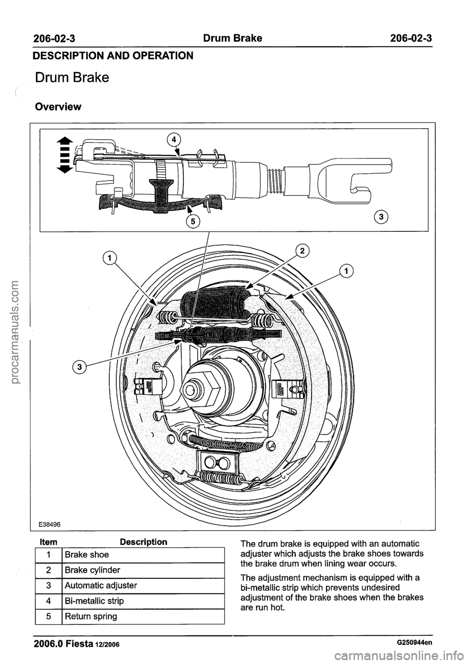
Overview
2006.0 Fiesta 1212006 G250944en
Item Description The drum brake is equipped with an automatic
adjuster which adjusts the brake shoes towards
the brake drum when lining wear occurs.
The adjustment mechanism is equipped with a
bi-metallic strip which prevents undesired
adjustment of the brake shoes when the brakes
are run hot.
1
2
3
4
5
Brake shoe
Brake cylinder
Automatic adjuster
Bi-metallic strip
Return spring
procarmanuals.com
Page 210 of 1226
206-0214 Drum Brake 206-02-4
DESCRIPTION AND OPERATION
The heat generated during braking is passed to
the bi-metallic strip. If the heat exceeds a critical
point, the bi-metallic strip bends upwards into the
corresponding nib and prevents further adjustment.
After the brake has cooled again, the bi-metallic
strip returns to the initial position. Adjustment is
now possible again.
2006.0 Fiesta 1212006 G250944en
procarmanuals.com