lock FORD FIESTA 2007 Workshop Manual
[x] Cancel search | Manufacturer: FORD, Model Year: 2007, Model line: FIESTA, Model: FORD FIESTA 2007Pages: 1226, PDF Size: 61.26 MB
Page 1061 of 1226
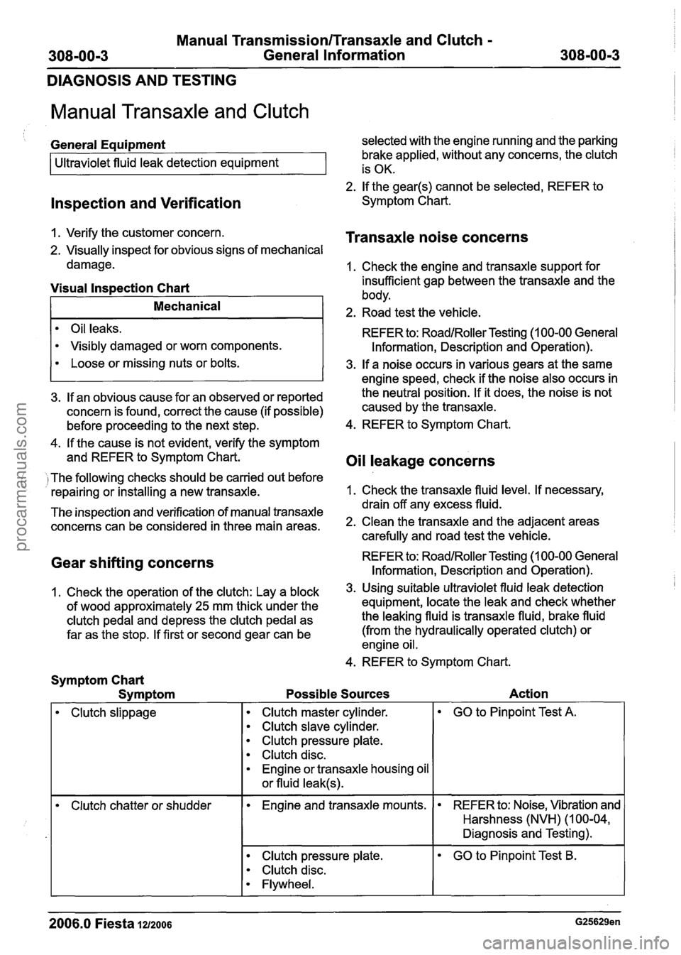
Manual Transmission/Transaxle and Clutch -
308-00-3 General Information 308-00-3
DIAGNOSIS AND TESTING
Manual Transaxle and Clutch
lnspection and Verification
General Equipment selected with the engine running and the parking
brake applied, without any concerns, the clutch
2. If the gear@) cannot be selected, REFER to
Symptom Chart.
Ultraviolet
fluid leak detection equipment
1. Verify the customer concern.
Transaxle noise concerns
2. Visually inspect for obvious signs of mechanical is
OK.
damage. 1. Check the engine and transaxle support for
Oil leaks.
Visibly damaged or worn components.
Visual lnspection Chart insufficient gap between the transaxle and the
body.
REFER to:
RoadlRoller Testing (1 00-00 General
Information, Description and Operation).
Mechanical 2. Road test the vehicle.
4. If the cause is not evident, verify the symptom
and REFER to Symptom Chart.
Oil leakage concerns
Loose or missing nuts or bolts.
( I The following checks should be carried out before
repairing or installing a new transaxle. 1.
Check the transaxle fluid level. If necessary,
3. If a noise occurs in various gears at the same
- - drain off any excess fluid.
The inspection and verification of manual transaxle
concerns can be considered in three main areas. 2. Clean the transaxle and the adjacent areas
carefully and road test the vehicle.
engine speed,
check if the noise also occurs in
3. If an obvious cause for an observed or reported the neutral position.
If it does, the noise is not
concern is found, correct the cause (if possible) caused
by the transaxle.
before proceeding to the next step. 4.
REFER to Symptom Chart.
Gear shifting concerns REFER to: RoadlRoller Testing (1 00-00 General
Information, Description and Operation).
1, Check the operation of the clutch: Lay a block 3. U~ing suitable ultraviolet fluid leak detection
of wood approximately
25 mm thick under the equipment, locate
the leak and check whether
clutch pedal and depress the clutch pedal as the leaking fluid
is transaxle fluid, brake fluid
far as the stop. If first or second gear can be (from the hydraulically operated clutch)
or
engine oil.
4. REFER to Symptom Chart.
Symptom Chart
Symptom Possible Sources Action
I
Clutch slippage Clutch master
cylinder.
Clutch slave cylinder.
Clutch pressure plate.
Clutch disc.
Engine or transaxle housing oil
or fluid
leak@).
GO to Pinpoint Test A.
Clutch chatter or shudder Engine and transaxle
mounts. REFER to:
Noise, Vibration and
Harshness (NVH) (1 00-04,
Diagnosis and Testing).
Clutch pressure plate.
Clutch disc.
Flywheel.
--
GO to Pinpoint Test B.
- -
2006.0 Fiesta 1212006 G25629en
procarmanuals.com
Page 1064 of 1226
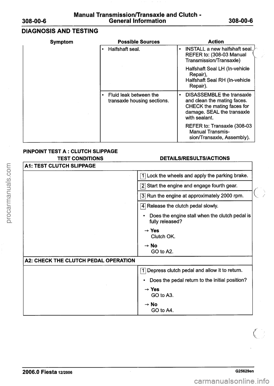
Manual Transmission/Transaxle and Clutch -
308-00-6 General Information 308-00-6
DIAGNOSIS AND TESTING
Symptom Possible Sources
Action
Halfshaft seal. INSTALL
a new halfshaft seal.
REFER to: (308-03 Manual
Transmission/Transaxle)
Halfshaft Seal LH (In-vehicle
Repair),
Halfshaft Seal RH (In-vehicle
Repair).
Fluid leak between the
transaxle housing sections. DISASSEMBLE the transaxle
and clean the mating faces.
CHECK the mating faces for
damage. SEAL the transaxle
with sealant.
REFER to: Transaxle (308-03
Manual Transmis-
sion/-rransaxle, Assembly).
PINPOINT TEST A
: CLUTCH SLIPPAGE
TEST CONDITIONS
DETAILSIRESU LTSIACTIONS
Al: TEST CLUTCH SLIPPAGE
Lock the wheels and apply the parking brake.
Start the engine and engage fourth gear.
Run the engine at approximately 2000 rpm.
Release the clutch pedal slowly.
Does the engine stall when the clutch pedal is
fully released?
+ Yes Clutch OK.
+ No
GO to
A2.
A2: CHECK THE CLUTCH PEDAL OPERATION
Depress clutch pedal and allow it to return.
Does the pedal return to the initial position?
+ Yes
GO to A3.
-, No
GO to A4.
2006.0 Fiesta 1212006 G25629en
procarmanuals.com
Page 1069 of 1226
Manual Transmission/Transaxle and Clutch -
308-00-1 1 General Information 308-00-1 I
GENERAL PROCEDURES
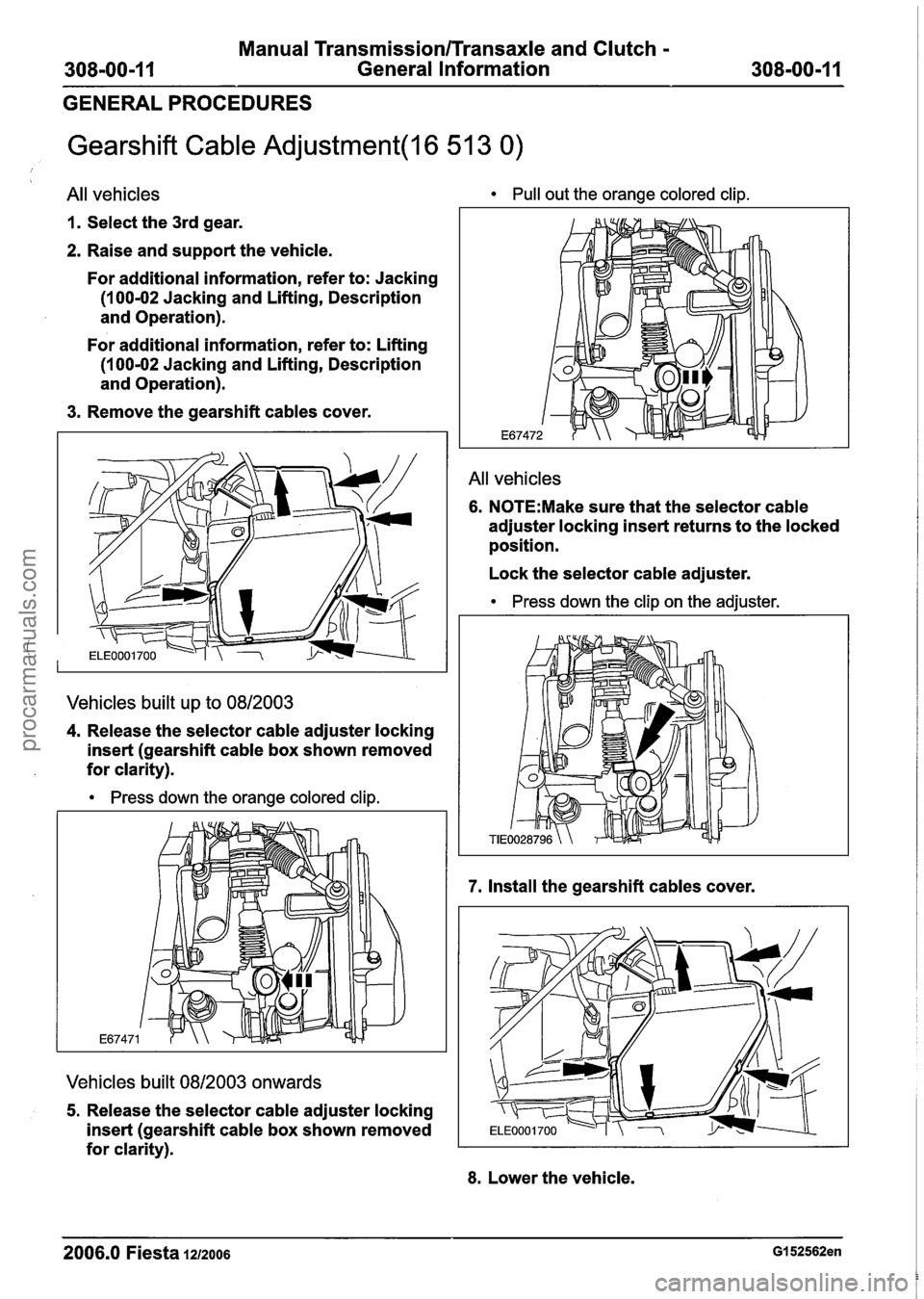
Gearshift Cable Adjustment(l6 51 3 0)
All vehicles
1. Select the 3rd gear.
2. Raise and support the vehicle.
For additional information, refer to: Jacking
(1
00-02 Jacking and Lifting, Description
and Operation).
For additional information, refer to: Lifting
(1
00-02 Jacking and Lifting, Description
and Operation).
3. Remove the gearshift cables cover.
Vehicles built up to 0812003
4. Release the selector cable adjuster locking
insert (gearshift cable box shown removed
for clarity).
Press down the orange colored clip.
Vehicles built 0812003 onwards
5. Release the selector cable adjuster locking
insert (gearshift cable box shown removed
for clarity).
Pull out the orange colored clip.
All vehicles
6. N0TE:Make sure that the selector cable
adjuster locking insert returns to the locked
position.
Lock the selector cable adjuster.
Press down the clip on the adjuster.
7. Install the gearshift cables cover.
8. Lower the vehicle.
2006.0 Fiesta 1212006 GI 52562en
procarmanuals.com
Page 1088 of 1226
308-02-8 Clutch Controls 308-02-8
REMOVAL AND INSTALLATION
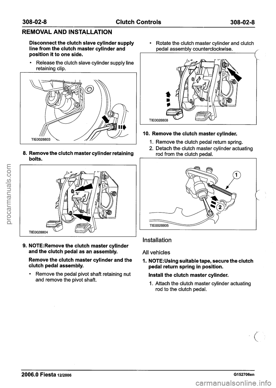
Disconnect the clutch slave cylinder supply Rotate the clutch master cylinder and clutch
line from the clutch master cylinder and pedal assembly counterclockwise.
position it to one side.
Release the clutch slave cylinder supply line
retaining clip.
8. Remove the clutch master cylinder retaining
bolts.
10. Remove the clutch master cylinder.
1. Remove the clutch pedal return spring.
2. Detach the clutch master cylinder actuating
rod from the clutch pedal.
Installation
9. N0TE:Remove the clutch master cylinder
and the clutch pedal as an assembly.
All vehicles
Remove the clutch master cylinder and the 1. N0TE:Using suitable tape, secure the clutch
clutch pedal assembly.
pedal return spring in position.
Remove the pedal pivot shaft retaining nut Install the clutch master cylinder.
and remove the pivot shaft. I. Attach the clutch master cylinder actuating
rod to the clutch pedal.
2006.0 Fiesta 1212006 GI 52706en
procarmanuals.com
Page 1089 of 1226
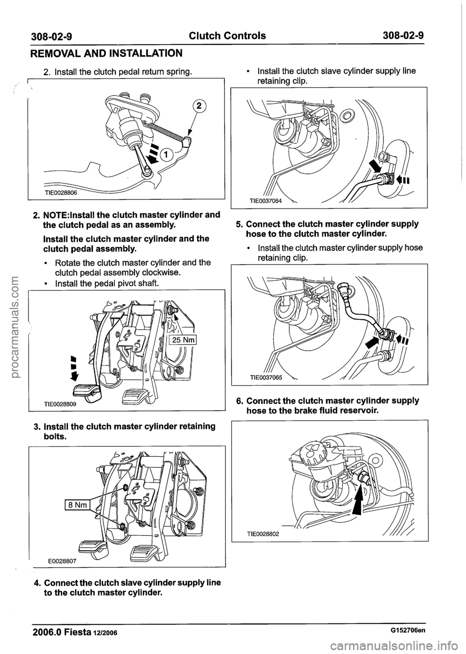
308-02-9 Clutch Controls 308-02-9
REMOVAL AND INSTALLATION
2. N0TE:lnstall the clutch master cylinder and
2. Install the clutch pedal return spring. Install the clutch slave cylinder supply line
the clutch pedal as an assembly: 5. Connect the clutch master cylinder supply
lnstall the clutch master cylinder and the hose
to the clutch master cylinder.
clutch pedal assembly.
Install the clutch master cylinder supply hose
I
Rotate the clutch master cylinder and the retaining
clip. I I
retaining clip. I I
clutch pedal assembly clockwise.
lnstall the pedal pivot shaft.
3. lnstall the clutch master cylinder retaining
bolts.
4. Connect the clutch slave cylinder supply line
to the clutch master cylinder.
6. Connect the clutch master cylinder supply
hose to the brake fluid reservoir.
2006.0 Fiesta 1212006 GI 52706en
procarmanuals.com
Page 1100 of 1226
308-03-1 0 Manual Transmission/Transaxle 308-03-1 0
DESCRIPTION AND OPERATION
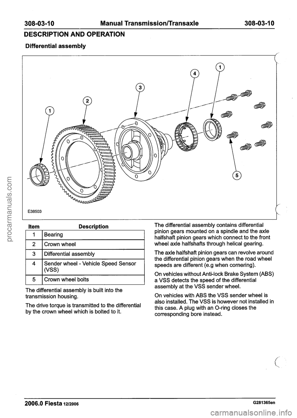
Differential assembly
Item Description
I 1 1 Bearing I
1 2 1 Crown wheel I
1 3 1 Differential assembly I
4 Sender wheel - Vehicle Speed Sensor
I I (VSS)
The differential assembly is built into the
transmission housing.
The drive torque is transmitted to the differential
by the crown wheel which is bolted to it. The differential
assembly contains differential
pinion gears mounted on a spindle and the axle
halfshaft pinion gears which connect to the front
wheel axle halfshafts through helical gearing.
The axle halfshaft pinion gears can revolve around
the differential pinion gears when the road wheel
speeds are different
(e.g when cornering).
On vehicles without Anti-lock Brake System (ABS)
a VSS detects the speed of the differential
assembly at the VSS sender wheel.
On vehicles with ABS the VSS sender wheel is
also installed. The VSS is however not installed in
this case. A plug with an O-ring closes the
corresponding bore instead.
2006.0 Fiesta la2006 G281365en
procarmanuals.com
Page 1101 of 1226
308-03-1 1 Manual Transmission/Transaxle 308-03-1 1
DESCRIPTION AND OPERATION
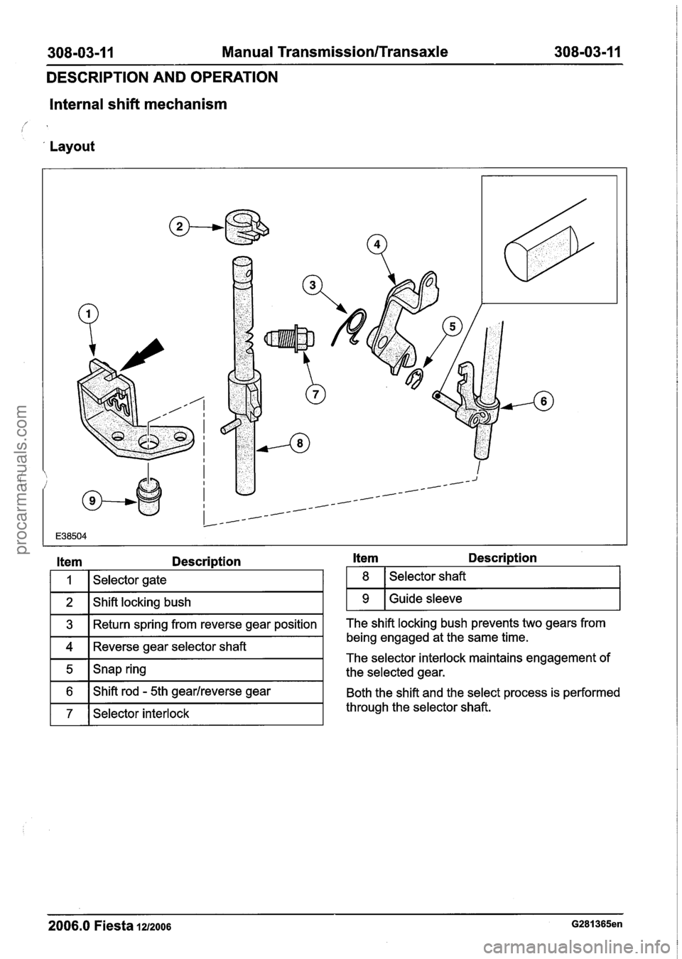
Internal shift mechanism
'
' Layout
Item Description
I I I Selector gate I
1 3 1 Return spring from reverse gear position I
1 4 1 Reverse gear selector shaft I
-
1 7 1 Selector interlock I
5
6
Itern Descri~tion
Snap ring
Shift rod
- 5th gearlreverse gear
1 8 1 Selector shaft I
1 9 1 Guide sleeve I
The shift locking bush prevents two gears from
being engaged at the same time.
The selector interlock maintains engagement of
the selected gear.
Both the shift and the select process is performed
through the selector shaft.
2006.0 Fiesta 121zoo6 G281365en
procarmanuals.com
Page 1102 of 1226
308-03-1 2 Manual Transmission/Transaxle 308-03-1 2
DESCRIPTION AND OPERATION
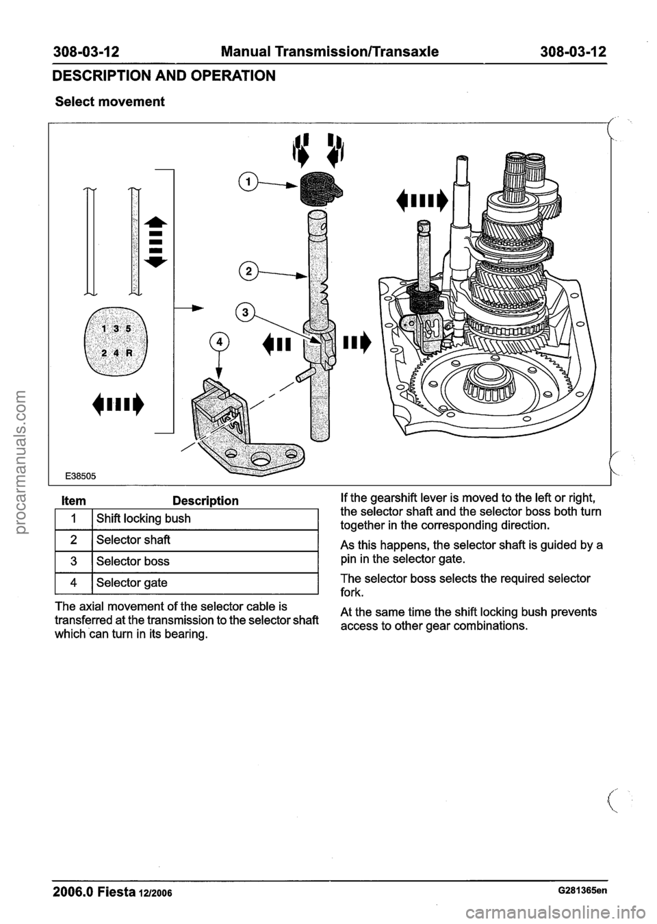
Select movement
/
Item Description If the gearshift lever is moved to the left or right,
1
2
3
The axial movement of the selector cable is
At the same time the shift locking bush prevents
transferred at the transmission to the selector shaft
access to other gear combinations~ which can turn in its bearing.
Shift locking
bush
4
2006.0 Fiesta 1212006 G281365en
the selector shaft and the selector boss both turn
together in the corresponding direction.
Selector shaft
Selector boss As this
happens, the selector shaft is guided by a
pin in the selector gate.
fork.
Selector gate
The
selector boss selects the required selector
procarmanuals.com
Page 1103 of 1226
308-03-1 3 Manual Transmission/Transaxle 308-03-1 3
DESCRIPTION AND OPERATION
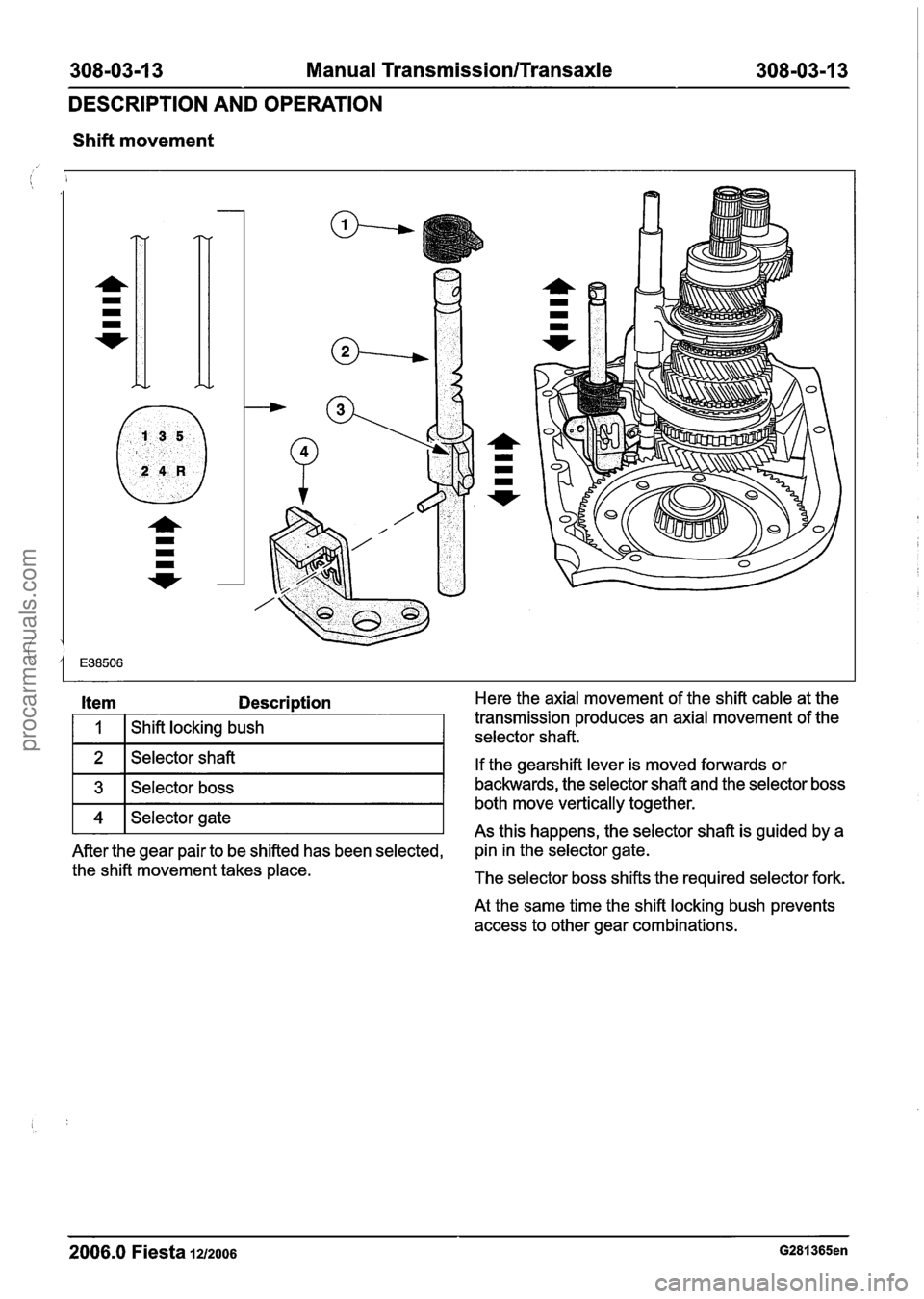
Shift movement
Item Descri~tion Here the axial movement of the shift cable at the
If the gearshift lever is moved forwards or
backwards, the selector shaft and the selector boss
both move vertically together.
As this happens, the selector shaft is guided by a .
After the gear pair to be shifted has been selected, pin
in the selector gate.
the shift movement takes place. The selector boss shifts the required selector fork.
1
At the same time the shift locking bush prevents
access to other gear combinations.
Shift locking bush
2006.0 Fiesta 1212006 G281365en
transmission produces
an axial movement of the
. selector shaft.
procarmanuals.com
Page 1104 of 1226
308-03-1 4 Manual Transmission/Transaxle 308-03-1 4
DESCRIPTION AND OPERATION
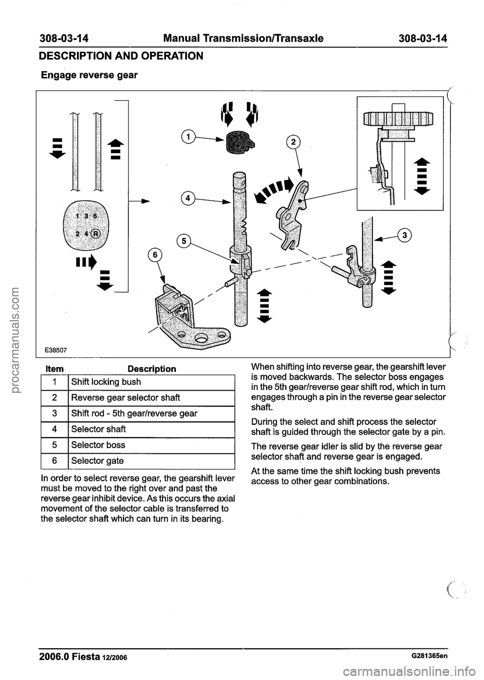
Engage reverse gear
Item Descri~tion When shifting into reverse gear, the gearshift lever
engages through a pin in the reverse gear selector
shaft.
During the select and shift process the selector
shaft is guided through the selector gate by a pin.
1 Shift locking bush
movement of the selector cable is transferred to is
moved backwards. The selector boss engages
in the 5th gearlreverse gear shift rod, which in turn
5
6
the selector shaft which can turn in its bearing.
2006.0 Fiesta la2006 G281365en
At the same time the shift locking bush prevents In order to select reverse gear, the gearshift kver access to other gear combinations, must be moved to the right over and past the
reverse gear inhibit device. As this occurs the axial
Selector boss
Selector gate
The reverse gear idler
is slid by the reverse gear
selector shaft and reverse gear is engaged.
procarmanuals.com