ESP FORD FIESTA 2007 Owner's Manual
[x] Cancel search | Manufacturer: FORD, Model Year: 2007, Model line: FIESTA, Model: FORD FIESTA 2007Pages: 1226, PDF Size: 61.26 MB
Page 486 of 1226
303-01 A-I 0
Engine - I .25L Duratec-1 6V (Sigma)ll.4L
Duratec-1 6V (Sigma)/l .6L Duratec-1 6V (Sigma)
DESCRIPTION AND OPERATION
Engine Engine emission control
Cross-mounted 16-valve DOHC engines with 59 European emissions level IV
kW (80 PS) and 74 kW (1 00 PS) respectively.
European on-board diagnosis (EOBD) for the
Valve train with mechanical bucket tappets monitoring of emissions-relevant components.
Cylinder block and cylinder head made of an
aluminium alloy
Diagnosis
Auxiliary drive via a self-tensioning belt without a
belt tensioner WDS diagnosis CD
817.
Instrument cluster (engine indicator lamp)
Engine management
Sequential multi-port fuel injection (SFI)
temperature and manifold absolute pressure (T-MAP) sensor in conjunction with a Siemens
powertrain control module (PCM).
Knock control
PCM with 84 pins and integrated passive anti-theft
system (PATS) immobiliser. Torquelpower
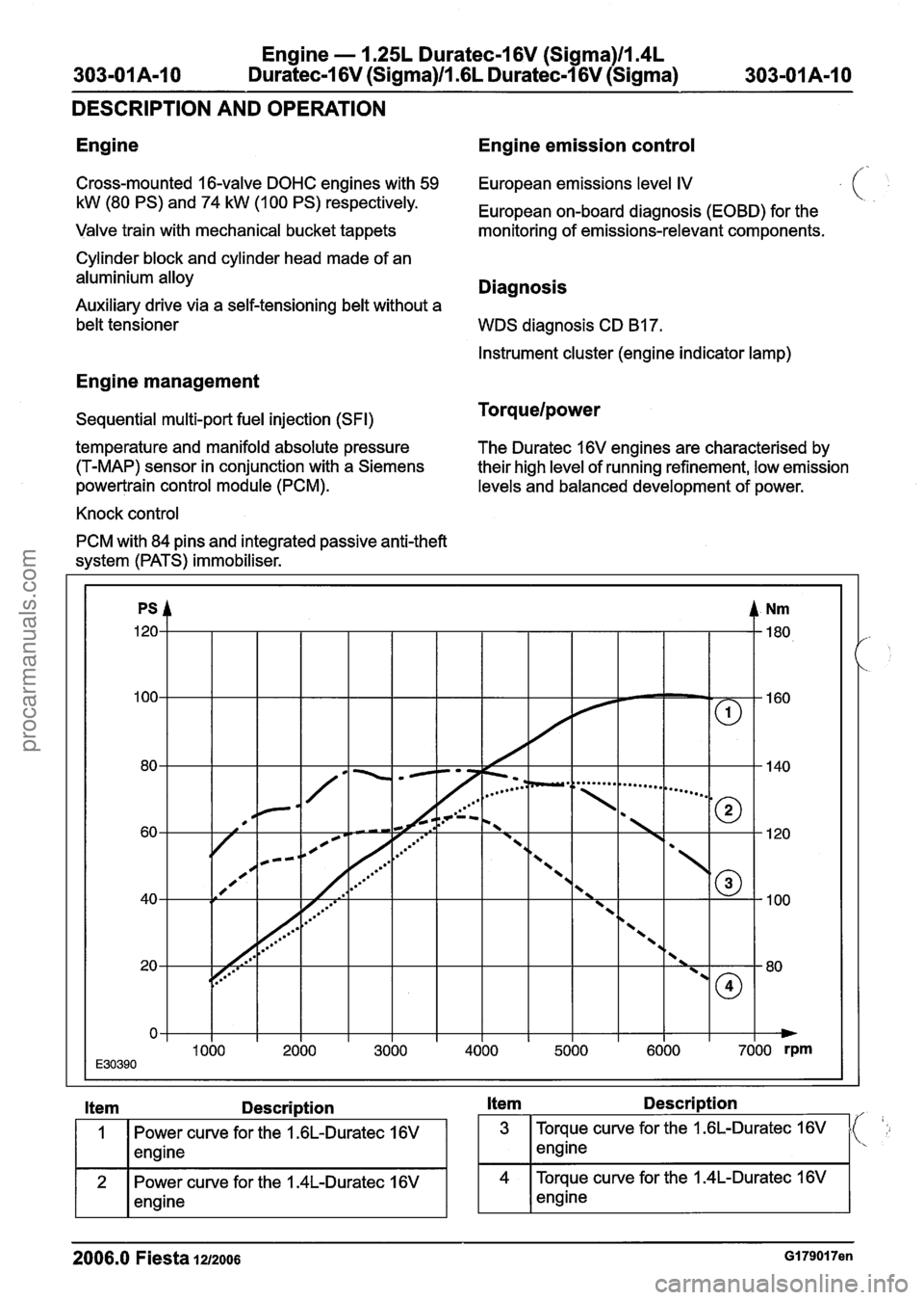
The Duratec 16V engines are characterised by
their high level of running refinement, low emission
levels and balanced development of power.
Description Description
Power curve for the 1.6L-Duratec 16V 3 Torque curve for the 1.6L-Duratec 16V ( ',I
Power curve for the 1.4L-Duratec 16V 4
Torque
curve for the 1.4L-Duratec 16V
2006.0 Fiesta 1212006 GI 7901 7en
procarmanuals.com
Page 625 of 1226
Engine - 2.OL Duratec-HE (M14)
SPECIFICATIONS
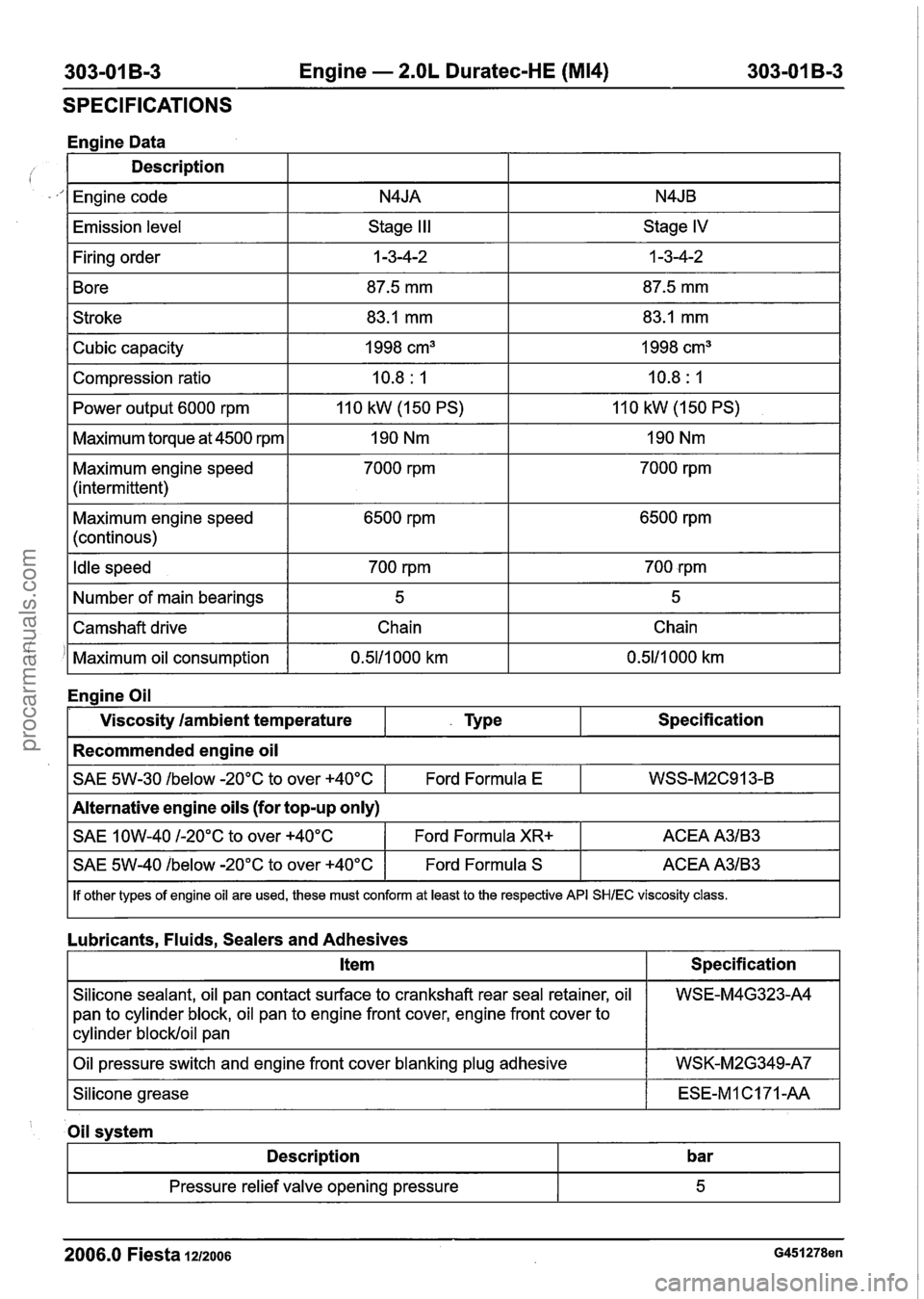
Engine Data
Description
I Engine code I N4JA I N4JB I
IEmission level I Stage III I Stage IV I
I Firing order I 1 -3-4-2 I 1 -3-4-2 I
1 Bore I 87.5 mm I 87.5 mm I
1 Stroke I 83.1 mm I 83.1 mm I
I Power output 6000 rpm 1 110 kW (150 PS) I 110 kW (1 50 PS) I
Cubic capacity
Compression ratio
I Maximum torque at 4500 rpm I 190 Nm I 190 Nm I
Maximum engine speed
(intermittent) 1998
cm3
10.8
: I
7000 rprn 1998
cm3
10.8
: 1
7000 rprn
Maximum engine speed
(continous) 6500
rprn 6500 rprn
I Idle speed I 700 rpm I 700 rpm I
I Number of main bearings I 5 I 5 I
!
Engine Oil
I SAE 1 OW-40 I-20°C to over +40°C I Ford Formula XR+ I ACEA A3lB3 I
Camshaft drive
Maximum oil consumption
Viscosity
/ambient temperature
Recommended engine oil
~40%%0w -20°C to over +40°C I Ford Formula S I ACEA A3lB3 I
SAE 5W-30 /below -20°C to over +40°C
I If other types of engine oil are used, these must conform at least to the respective API SHlEC viscosity class.
Chain
0.5111 000 km
- Type
Lubricants, Fluids, Sealers and Adhesives Chain
0.5111 000 km
Specification
Alternative engine oils (for top-up only) Ford Formula
E
I Item I Specification I
WSS-M2C913-B
I Oil pressure switch and engine front cover blanking plug adhesive I WSK-M2G349-A7 I
Silicone sealant, oil pan contact surface to crankshaft rear seal retainer, oil
pan to
cylinder block, oil pan to engine front cover, engine front cover to
cylinder blockloil pan
ISilicohe grease I ESE-MlC171-AA I
WSE-M4G323-A4
' Oil svstem
I Description I bar I
2006.0 Fiesta 1212006 G451278en
- -
Pressure relief valve opening pressure 5
procarmanuals.com
Page 759 of 1226
Engine Cooling - I .3L Duratec-8V
(Rocam)llm25L Duratec-1 6V (Sigma)ll.4L
303-03A-17 Duratec-1 6V (Sigma)/lm6L Duratec-1 6V (Sigma) 303-03A-17
DIAGNOSIS AND TESTING
RPM - engine speed
i DSRPM - desired engine speed
The IAT sensor output is useful if the engine being
tested is cold or after an over-night cold soak. The
ECT sensor or CHT sensor and the IAT sensor
should either indicate the same value or be within
1 to 2 degrees Celsius of each other.
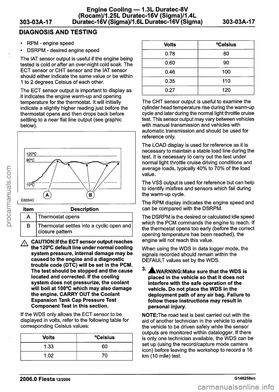
The ECT sensor output is important to display as
it indicates the engine warm-up and opening
temperature for the thermostat. It will initially
indicate a slightly higher reading just before the
thermostat opens and then drops back before
settling to a near flat line output (see graphic
below).
Item Description
I A I Thermostat opens I
B Thermostat settles into a cyclic open and
I I closure pattern
A CAUTI0N:lf the ECT sensor output reaches
the
120°C default line under normal cooling
system pressure, internal damage may be
caused to the engine and a diagnostic
trouble code (DTC) will be set in the PCM.
The test should be stopped and the cause
located and corrected. If the cooling
system does not pressurize, the coolant
will boil at
100°C which may also damage
the engine. CARRY OUT the Coolant
Expansion Tank Cap Pressure Test
Component Test in this section.
If the WDS only allows the ECT sensor to be
displayed in volts, refer to the following table for
corresponding Celsius values:
Volts
OCelsius
The CHT sensor output is useful to examine the
cylinder head temperature rise during the warm-up
cycle and later during the normal light throttle cruise
test. This sensor output may vary between vehicles
with manual transmission and vehicles with
automatic transmission and should be used for
reference only.
Volts
0.78
0.60
0.46
0.35
0.27
The
LOAD display is used for reference as it is
necessary to maintain a stable load line during the
test. It is necessary to carry out the test under
normal light throttle cruise driving conditions and
average loads, typically
40% to 70% of the load
value.
OCelsius
80
90
100
11 0
120
The VSS output is used for reference but can help
to identify misfires and sensors which fail during
the warm-up cycle.
The RPM display indicates the engine speed and can be compared with the DSRPM.
The DSRPM is the desired or calculated idle speed
which the PCM commands the engine to reach. If
the thermostat opens too early (before the correct
opening temperature has been reached), the
engine will not reach this value.
When using the WDS in data logger mode, the
signals recorded should remain within the
DEFAULT values set by the WDS.
3m AWARNING:M~~~ sure that the WDS is
placed in the vehicle so that it does not
interfere with the safe operation of the
vehicle. Do not place the WDS in the
deployment path of any air bag. Failure to
follow these instructions may result in personal injury.
N0TE:The road test is best carried out with the
aid of another technician in the vehicle to enable
the vehicle to be driven safely while the sensor
outputs are monitored within datalogger. If there
is only one technician available, the WDS can be
set up (using the
recordlcapture mode camera
icon) before leaving the workshop to record a
16
km (1 0 mile) test.
2006.0 Fiesta 1212006 GI 46258en
procarmanuals.com
Page 785 of 1226
303-03B-15 Engine Cooling - 2.OL Duratec-HE (M14) 303-03B-15
DIAGNOSIS AND TESTING
A CAUTI0N:lf the ECT sensor output reaches
the
120°C default line under normal cooling
system pressure, internal damage may be
caused to the engine and a diagnostic
trouble code (DTC) will be set in the PCM.
The test should be stopped and the cause
located and corrected. If the cooling
system does not pressurize, the coolant
will boil at
1 OO°C which may also damage
the engine. CARRY
OUT the Coolant
Expansion Tank Cap Pressure Test
Component Test in this section.
If the WDS only allows the ECT sensor to be
displayed in volts, refer to the following table for
corresponding Celsius values:
The CHT sensor output is useful to examine the
cylinder head temperature rise during the warm-up
cycle and later during the normal light throttle cruise
test. This sensor output may vary between vehicles
with manual transmission and vehicles with automatic transmission and should be used for
reference only.
Volts
1.33
1.02
0.78
0.60
0.46
0.35 0.27
The LOAD display is used for reference as it is
necessary to maintain a stable load line during the
test. It is necessary to carry out the test under
normal light throttle cruise driving conditions and
average loads, typically 40% to 70% of the load
value.
OCelsius
60
70
80
90
100
110
120 '
The VSS output is used for reference but can help
to identify misfires and sensors which fail during
the warm-up cycle.
The RPM display indicates the engine speed and
can be compared with the DSRPM.
The DSRPM is the desired or calculated idle speed
which the PCM commands the engine to reach. If
the thermostat opens too early (before the correct
opening temperature has been reached), the
engine will not reach this value. When
using the WDS in data logger mode, the
signals recorded should remain within the
DEFAULT values set by the WDS.
3m AWARNING:M~~~ sure that the WDS is
placed in the vehicle so that it does not
interfere with the safe operation of the
vehicle. Do not place the WDS in the
deployment path of any air bag. Failure to
follow these instructions may result in personal injury.
N0TE:The road test is best carried out with the
aid of another technician in the vehicle to enable
the vehicle to be driven safely while the sensor
outputs are monitored within datalogger. If there
is only one technician available, the WDS can be
set up (using the
recordlcapture mode camera
icon) before leaving the workshop to record a 16
km (1 0 mile) test.
N0TE:The results from the test are more
conclusive if the engine is cold when the test is
started.
Carry out a road test.
REFER to:
RoadIRoller Testing (1 00-00 General
Information, Description and Operation).
4. Drive the vehicle at a constant throttle opening
and set speed until the ECT value settles into
a shallow rise and fall signal, close to a straight
line. This indicates that the thermostat is
functioning correctly.
N0TE:Some thermostats indicate the
temperature(s) in Celsius and Fahrenheit.
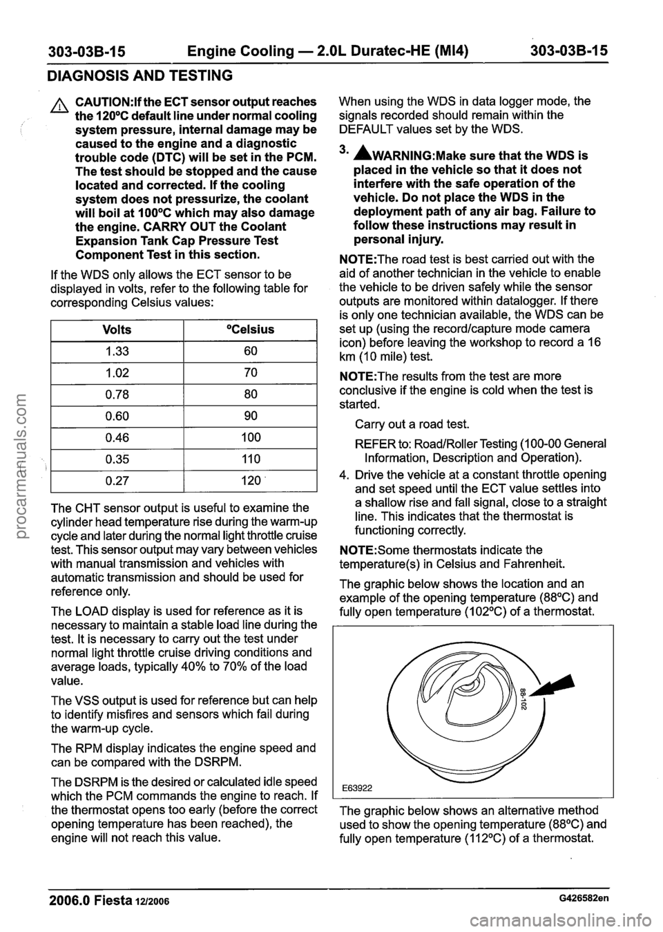
The graphic below shows the location and an
example of the opening temperature
(88OC) and
fully open temperature (1
02OC) of a thermostat.
The graphic below shows an alternative method used to show the opening temperature
(88OC) and
fully open temperature
(112OC) of a thermostat.
2006.0 Fiesta 1212006 G426582en
procarmanuals.com
Page 855 of 1226
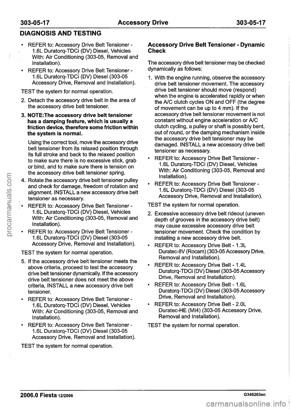
303-05-1 7 Accessory Drive 303-05-1 7
DIAGNOSIS AND TESTING
REFER to: Accessory Drive Belt Tensioner -
1.6L Duratorq-TDCi (DV) Diesel, Vehicles i With: Air Conditioning (303-05, Removal and
Installation).
REFER to: Accessory Drive Belt Tensioner
-
1.6L Duratorq-TDCi (DV) Diesel (303-05
Accessory Drive, Removal and lnstallation).
TEST the system for normal operation.
2. Detach the accessory drive belt in the area of
the accessory drive belt tensioner.
3. N0TE:The accessory drive belt tensioner
has a damping feature, which is usually a
friction device, therefore some friction within
the system is normal.
Using the correct tool, move the accessory drive
belt tensioner from its relaxed position through
its full stroke and back to the relaxed position
to make sure there is no excessive stick, grab
or bind, and to make sure there is tension on
the accessory drive belt tensioner spring.
4. Rotate the accessory drive belt tensioner pulley
and check for damage, freedom of rotation and
alignment. INSTALL a new accessory drive belt
tensioner as necessary.
Accessory Drive Belt Tensioner - Dynamic
Check
The accessory drive belt tensioner may be checked
dynamically as follows:
1. With the engine running, observe the accessory
drive belt tensioner movement. The accessory
drive belt tensioner should move (respond)
when the engine is accelerated rapidly or when
the
A/C clutch cycles ON and OFF (the degree
of movement can be up to 4 mm). If the
accessory drive belt tensioner movement is not
constant without engine acceleration or
A/C
clutch cycling, a pulley or shaft is possibly bent,
out of round, or the damping mechanism inside
the accessory drive belt tensioner may be
damaged. INSTALL a new accessory drive belt
tensioner as necessary.
REFER to: Accessory Drive Belt Tensioner
-
1.6L Duratorq-TDCi (DV) Diesel, Vehicles
With: Air Conditioning (303-05, Removal and
Installation).
REFER to: Accessory Drive Belt Tensioner -
1.6L Duratorq-TDCi (DV) Diesel (303-05
Accessory Drive, Removal and lnstallation).
( :I. REFER to: Accessory Drive Belt Tensioner - TEST the system for normal operation.
1.6L Duratorq-TDCi (DV) Diesel, Vehicles
2. Excessive accessory drive belt rideout (uneven
With: Air Conditioning (303-05, Removal and
depth of grooves in the accessory drive belt)
Installation). may cause excessive accessory drive belt
REFER to: Accessory Drive Belt Tensioner
- tensioner movement. Check the condition by
1.6L Duratorq-TDCi (DV) Diesel (303-05
installing a new accessory drive belt.
Accessory Drive, Removal and
installation). . REFER to: Accessory Drive Belt - 1.3~
TEST the system for normal operation. Duratec-8V (Rocam) (303-05 Accessory
Drive,
5. If the accessory drive belt tensioner meets the
above criteria, proceed to test the accessory
drive belt tensioner dynamically. If the accessory
drive belt tensioner does not meet the above
criteria, INSTALL a new accessory drive belt
tensioner.
REFER to: Accessory Drive Belt Tensioner
-
1.6L Duratorq-TDCi (DV) Diesel, Vehicles
With: Air Conditioning (303-05, Removal and
Installation).
REFER to: Accessory Drive Belt Tensioner
-
1.6L Duratorq-TDCi (DV) Diesel (303-05
Accessory Drive, Removal and Installation).
TEST the system for normal operation. Removal and Installation).
REFER to: Accessory Drive Belt
- 1.4L
Duratorq-TDCi (DV) Diesel (303-05 Accessory
Drive, Removal and Installation).
REFER to: Accessory Drive Belt - 1.6L
Duratorq-TDCi (DV) Diesel (303-05 Accessory
Drive, Removal and Installation).
REFER to: Accessory Drive Belt
- 2.OL
Duratec-H E (M 14) (303-05 Accessory Drive,
Removal and Installation).
TEST the system for normal operation.
2006.0 Fiesta 12/2006 G346263en
procarmanuals.com
Page 940 of 1226
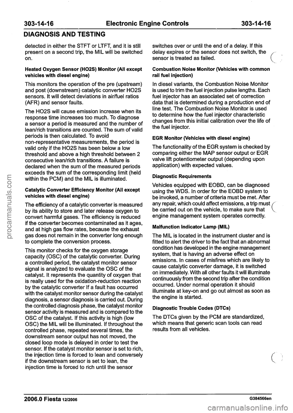
Electronic Engine Controls
DIAGNOSIS AND TESTING
detected in either the STFT or LTFT, and it is still
present on a second trip, the MIL will be switched
on.
Heated Oxygen Sensor (H02S) Monitor (All except
vehicles with diesel engine)
This monitors the operation of the pre (upstream)
and post (downstream) catalytic converter
H02S
sensors. It will detect deviations in airlfuel ratios
(AFR) and sensor faults.
The
H02S will cause emission increase when its
response time increases too much. To diagnose
a sensor a period is measured and the number of
leanlrich transitions are counted. The sum of valid
periods is then calculated. To avoid
non-representative measurements, the period is
valid only if the
H02S has been below a low
threshold and above a high threshold between 2
consecutive leanlrich transitions.
A failure is
declared when the sum of the measured periods
exceeds the sum of the corresponding limit (held
within the PCM) and the MIL is illuminated.
Catalytic Converter Efficiency Monitor (All except
vehicles with diesel engine)
The efficiency of a catalytic converter is measured
by its ability to store and later release oxygen to
convert harmful gases. The efficiency is reduced
if the converter becomes contaminated as it ages,
and at high gas flow rates, because the exhaust
gas does not remain in the converter long enough
to complete the conversion process. switches
over or until the end of a delay. If this
delay expires or the sensor does not switch, the
sensor is treated as failed.
Combustion Noise Monitor (Vehicles with common
rail fuel injection)
In diesel variants, the Combustion Noise Monitor
is used to trim the fuel injection pulse lengths. Each
fuel injector has an associated set of correction
data that is determined during a production end of
line test. The Combustion Noise Monitor is used
to determine how the fuel injector characteristic
changes from this initial calibration over the life of
the fuel injector.
EGR Monitor (Vehicles with diesel engine)
The functionality of the EGR system is checked by
comparing either the MAP sensor output or EGR
valve lift potentiometer output (depending upon
application) with expected values.
Diagnostic Requirements
Vehicles equipped with EOBD, can be diagnosed
using the WDS. In order for the EOBD system to
be invoked, a number of criteria must be met. After
any repair, which could affect emissions, a trip must
be carried out on the vehicle, to make sure that
engine management system operates correctly.
Malfunction Indicator Lamp (MIL)
The MIL is located in the instrument cluster and is
fitted to alert the driver to the fact that an abnormal
This monitor checks for the oxygen storage condition
has developed in the engine management
capacity (OSC) of the catalytic converter. During system,
that is having an adverse effect on
a controlled period, the catalyst monitor sensor emissions.
In cases of misfires which are likely to
signal is analyzed to evaluate the OSC of the cause
catalytic converter damage, it is switched
catalyst. It represents the quantity of oxygen that on immediately.
With all other faults it will illuminate
is really used for the oxidation-reduction reaction continuously
from the second trip after the condition
by the catalytic converter If a fault has occurred occurred.
Under normal operation it should
with the catalyst monitor sensor during the catalyst illuminate
at key-on and go out almost as soon as
diagnosis, a sensor diagnosis is carried out. During the
engine is started.
the controlled diagnosis phase, the catalyst monitor
Diagnostic Trouble Codes (DTCs) sensor activity is measured and is compared to the
OSC of the catalyst. If this activity is high (low The
DTCs given
by the PCM are standardized,
0SC)theMILwillbeilluminated.Ifthroughoutthe whichmeansthatgenericscantoolscanread
controlled phase, repeated several times, the results from
all vehicles.
downstream sensor output has not moved, the
closed loop mode is delayed in order to test the
sensor. If the catalyst monitor sensor is set to rich,
the injection time is forced to lean and conversely
if the downstream sensor is set to lean, the
injection time is forced to rich until the sensor
2006.0 Fiesta 1212006 G384566en
procarmanuals.com
Page 942 of 1226
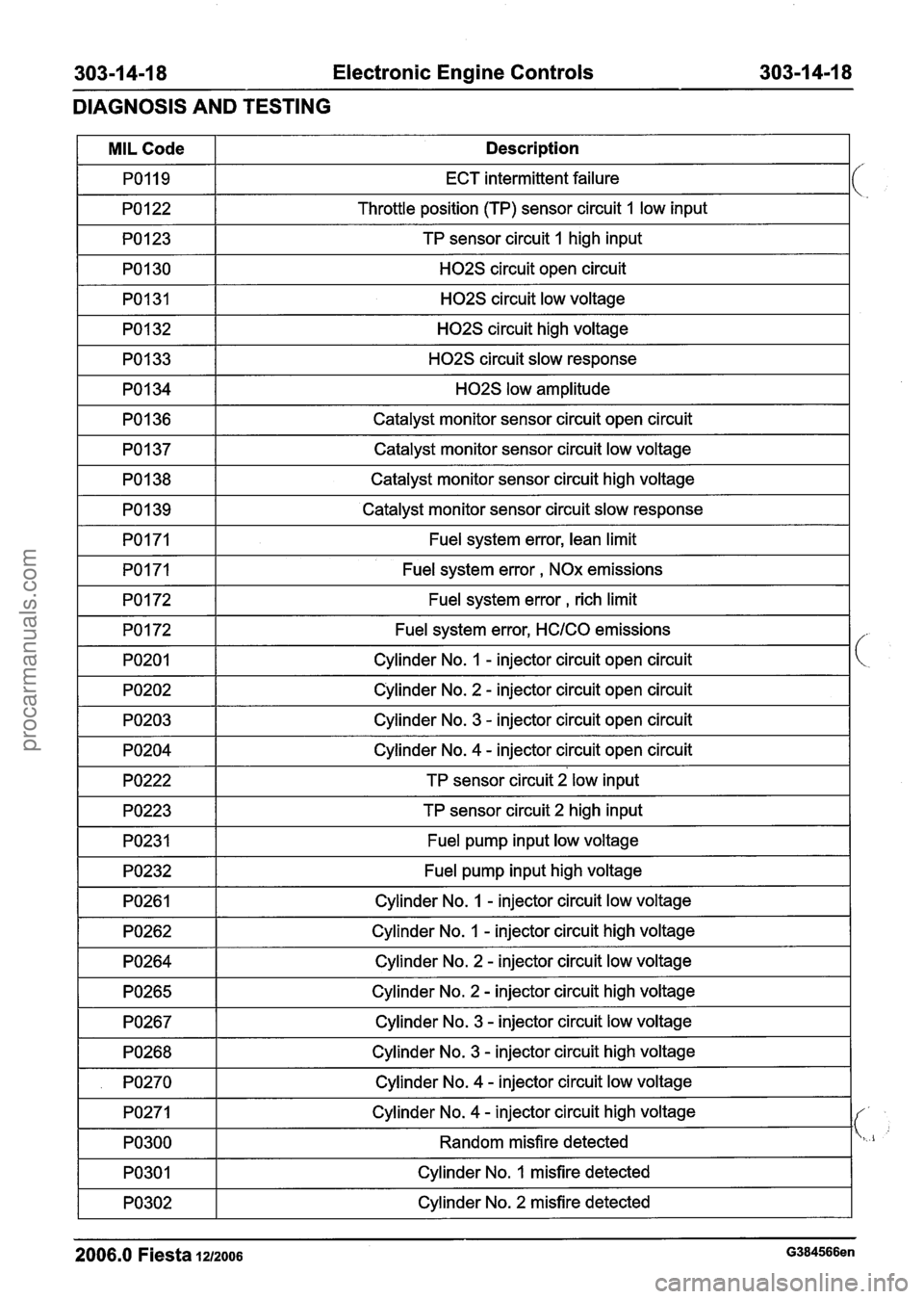
303-1 4-1 8 Electronic Engine Controls 303-1 4-1 8
DIAGNOSIS AND TESTING
I PO123 I TP sensor circuit I high input I
MIL Code
PO119
PO 1 22
I PO130 I H02S circuit open circuit I
Description
ECT intermittent failure
Throttle position
(TP) sensor circuit 1 low input
I PO131 I H02S circuit low voltage I
pol34 r- HO~S IOW amplitude I
PO1 32
PO1 33
I PO136 I Catalyst monitor sensor circuit open circuit I
H02S circuit high voltage
H02S circuit slow response
I PO137 I Catalyst monitor sensor circuit low voltage I
PO1 38
PO1 39
I PO172 I Fuel system error, rich limit I
Catalyst monitor sensor circuit high voltage
Catalyst monitor sensor circuit slow response
PO171
PO171
Fuel system error, lean limit
Fuel system error
, NOx emissions
PO172
PO201
I PO203 I Cylinder No. 3 - injector circuit open circuit I
Fuel system error, HClCO emissions
Cylinder No.
I - injector circuit open circuit
PO202
I PO204 I Cylinder No. 4 - injector circuit open circuit I
Cylinder No. 2 - injector circuit open circuit
-1 TP sensor circuit 2 low input I
1 PO223 1 TP sensor circuit 2 high input I
I PO231 I Fuel pump input low voltage I
PO232
PO261
Fuel pump input high voltage
Cylinder No.
1 - injector circuit low voltage
PO262
PO264
1 PO267 1 Cylinder No. 3 - injector circuit low voltage I
Cylinder No. 1 - injector circuit high voltage
Cylinder No.
2 - injector circuit low voltage
PO265
1 PO268 1 Cylinder No. 3 - injector circuit high voltage I
-- -
Cylinder No. 2 - injector circuit high voltage I
I . PO270 I Cylinder No. 4 - injector circuit low voltage I
PO271
PO300
Cylinder No. 4 - injector circuit high voltage
Random misfire detected
PO301
2006.0 Fiesta 1212006 G384566en
Cylinder No. 1 misfire detected
PO302
-- -
Cylinder No. 2 misfire detected
procarmanuals.com
Page 945 of 1226
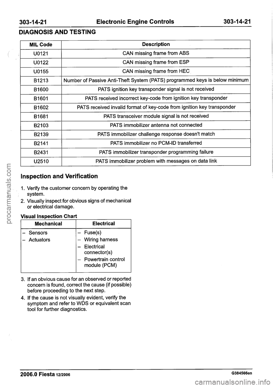
303-1 4-21 Electronic Engine Controls 303-1 4-21
DIAGNOSIS AND TESTING
lnspection and Verification
MIL Code
U0121
U0122
U0155
B1213
B1600
B1601
B1602
B1681
B2103
B2139
B2141
B2431
U2510
1. Verify the customer concern by operating the
( I system.
2. Visually inspect for obvious signs of mechanical
or electrical damage. Description
CAN missing frame from ABS
CAN missing frame from ESP
CAN missing frame from HEC
Number of Passive Anti-Theft System (PATS) programmed keys is below minimum
PATS ignition key transponder signal is not received
PATS received incorrect key-code from ignition key transponder
PATS received invalid format of key-code from ignition key transponder
PATS transceiver module signal is not received
PATS immobilizer antenna not connected
PATS immobilizer challenge response doesn't match
PATS immobilizer no PCM-ID transferred
PATS immobilizer transponder programming failure
PATS immobilizer problem with messages on data link
Visual Inspection Chart
Mechanical
I Electrical
- Sensors
- Actuators - Wiring harness
- Electrical
connector(s)
- Powertrain control
module (PCM)
3. If an obvious cause for an observed or reported
concern is found, correct the cause (if possible)
before proceeding to the next step.
4. If the cause is not visually evident, verify the
symptom and refer to WDS or equivalent scan
tool for further diagnostics.
- -
2006.0 Fiesta 1212006 G384566en
procarmanuals.com
Page 968 of 1226
Automatic Transmission/Transaxle -
Vehicles With: 4-Speed Automatic
Transmission
(AW81-40) 307-01 -8
DESCRIPTION AND OPERATION
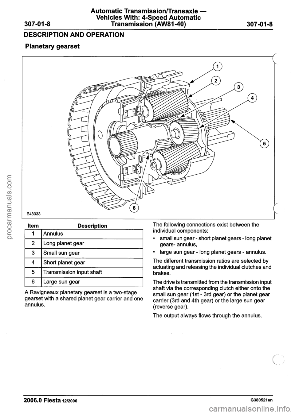
Planetary
gearset
Description The following connections exist between the
/ individual components:
small sun gear - short planet gears - long planet
Long planet gear gears- annulus,
3 Small sun gear large sun gear - long planet gears - annulus.
4
5
The output always flows through the annulus.
6
2006.0 Fiesta 1212006 ~380521 en
Short planet gear
Transmission input shaft The different transmission ratios
are selected by
actuating and releasing the individual clutches and
brakes.
shaft via the corresponding clutch either onto the
A Ravigneaux planetary gearset is a two-stage
small sun gear (1st - 3rd gear) or the planet gear gearset with a shared planet gear carrier and one carrier (3rd and 4th gear) or the large sun gear annulus. (reverse gear).
Large sun gear
The drive is transmitted from the transmission input
procarmanuals.com
Page 991 of 1226
Automatic TransmissionlTransaxle -
Vehicles With: 4-Speed Automatic
307-01 -31 Transmission (AW81-40) 307-01 -31
DESCRIPTION AND OPERATION
The transmission control unit determines hill climb
mode or trailer operation from the change in throttle
; valve position supplied by the PCM in relation to
the acceleration of the vehicle.
Depending on the driving resistance, the
transmission control unit chooses between two
gearshift maps which have been specially
programmed for this purpose and in which the shift
timings are again chosen as a function of the
accelerator pedal position and the vehicle speed..
Hill descent mode
The hill descent mode is used to take better
advantage of engine braking during hill descents.
A 'hill descent' situation is recognised by the
transmission control unit if the vehicle is
accelerating without operation of the accelerator
pedal.
If in addition the brake is also depressed then the
transmission control unit automatically shifts back
from 4th into 3rd gear.
( ' Cold start mode
In order to reach operating temperature as quickly
as possible under low ambient temperatures,
gearshifts into 4th gear and engagement of the
torque converter clutch (TCC) are suppressed if
one of the following conditions is met:
Transmission fluid temperature below +20 "C
Coolant temperature below - 40°C
The following are actuated: SSA shift solenoid valve,
SSB shift solenoid valve,
Shift solenoid valve, TCC.
Overheating protection mode
The overheating protection mode serves to protect
the transmission against overheating and the
serious damage that this can cause.
If the transmission fluid temperature reaches a
temperature of around 135
"C, the transmission
control employs a shift pattern designed to prevent
a further increase in the transmission fluid
temperature. When
the transmission fluid temperature drops
back below approx. 125
"C, the transmission
control exits the overheating protection mode.
The MIL warning lamp is actuated by the
transmission control unit if the transmission fluid
temperature reaches approximately 140
"C.
The MIL warning lamp goes out again when the
transmission fluid temperature drops back to below
around 130
"C.
Main line pressure control
In order to ensure the highest possible efficiency
of the automatic transmission and to limit the power
losses from the fluid pump, the main line pressure
is adapted accordingly by the main regulating valve
as a function of the accelerator pedal position
(driver torque demand) and the selector lever
position.
This is influenced by the following variables:
Accelerator pedal position and actuation
Selector lever position
The following are actuated:
Main 'regulating valve
Engagement of the TCC
The TCC is engaged in 3rd and 4th gear depending
on the current driving situation.
Engagement is controlled in accordance with the
shift map stored in the control unit.
This is influenced by the following variables:
Accelerator pedal position and actuation,
Vehicle speed,
Selector lever position,
Transmission fluid temperature,
Coolant temperature.
The following are actuated:
Shift solenoid valve, TCC.
Torque reduction during gearshifts
In order to improve the quality of gearshifts and to
avoid gearshift judder, the engine torque is reduced
by the PCM in response to a request from the
transmission control unit during gearshifts.
The engine torque is also reduced during
engagement and disengagement of the TCC.
2006.0 Fiesta 1212006 G380530en
procarmanuals.com