ESP FORD FIESTA 2007 User Guide
[x] Cancel search | Manufacturer: FORD, Model Year: 2007, Model line: FIESTA, Model: FORD FIESTA 2007Pages: 1226, PDF Size: 61.26 MB
Page 60 of 1226
100-04-4 Noise, Vibration and Harshness 100-0414
DIAGNOSIS AND TESTING
Noise, Vibration and Harshness (NVH)
Inspection and Verification
1. Verify the customer concern. Identify the Condition
2. Visually inspect for obvious signs of mechanical NVH usually occur in four areas:
or electrical damage.
tires
3. If an obvious cause for an observed or reported
concern is found, correct the cause (if possible) engine accessories
before proceeding to the next step.
suspension
4. If the concern is not visually evident, verify the
symptom and REFER to the Symptom Chart.
How to Use this Diagnostic Procedure
Section
Noise, vibration and harshness (NVH) concerns
have become more important as
vehjcles have
become more sensitive to these vibrations. This
section is designed to aid in identifying these
concerns.
The section provides diagnostic procedures based on symptom. If the condition occurs at
high speed, for instance, the most likely place
to start is under Shake and Vibration While
Driving.
The road test procedure will tell how to sort the
conditions into categories and how to tell a
vibration from a shake.
A series of Road Test Quick Checks are
provided to make sure that a cause is either
pinpointed or eliminated.
Name the condition, proceed to the appropriate
section and locate the correct diagnosis. When
the condition is identified, the job is partly done.
Follow the diagnostic procedure as outlined.
Quick Checks are described within the step,
while more involved tests and adjustments are
outlined in General Procedures.
Always follow each step exactly and make notes
to recall important findings later.
driveline
It is important, therefore, that an NVH concern be
isolated into its specific
area(s) as soon as
possible. The easiest and quickest way to do this
is to carry out the Road Test as outlined. To assist
in the diagnosis and testing
procedure(s), use a
suitable approved NVH diagnosis tester.
Noise Diagnostic Procedure
Non-Axle Noise
The five most common sources of non-axle noise
are exhaust, tires, roof racks, trim panels and
( transmission.
Therefore, make sure that none of the following
conditions are the cause of the noise before
proceeding with a driveline
teardown and
diagnosis.
In certain conditions, the pitch of the exhaust
may sound very much like gear noise. At other
times, it can be mistaken for a wheel bearing
rumble.
Tires, especially snow tires, can have a high
pitched tread whine or roar, similar to gear
noise. Radial tires may have this characteristic.
Also, any non-standard tire with an unusual
tread construction may emit a roar or whine
noise.
Trim panels can also cause whistling or whining
noise.
Clunk may be a metallic noise heard when the
Customer Interview automatic transaxle is engaged in "R
(REVERSE) or "D" (DRIVE) or it may occur
The road test and customer interview (if available) when
the throttle is applied or released. It is
provide information that will help identify the caused
by backlash somewhere in the driveline.
,
concern and will provide direction to the correct Bearing rumble sounds like marbles being
starting point for diagnosis. (
tumbled. This condition is usually caused by a
damaged wheel bearing.
2006.0 Fiesta 1212006 G37349en
procarmanuals.com
Page 174 of 1226
206-00-2 Brake System - General Information 206-00-2
DESCRIPTION AND OPERATION
Brake System
Overview
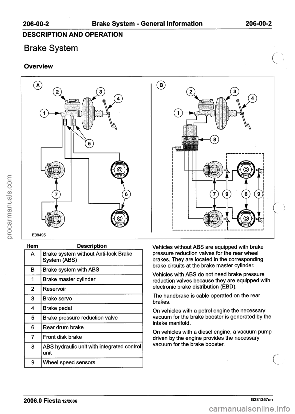
A Brake system without Anti-lock
Brake
I I system (ABS)
I B I Brake system with ABS I
I 1 I Brake master cylinder I -
1 2 1 Reservoir I
1 4 1 Brake pedal I
1 5 1 Brake pressure reduction valve I
1 6 1 Rear drum brake I
171t disk brake I
8 ABS hydraulic unit with integrated control
1 1 unit
1 9 I Wheel speed sensors I
Vehicles without ABS are equipped with brake
pressure reduction valves for the rear wheel
brakes. They are located in the corresponding
brake circuits at the brake master cylinder.
Vehicles with ABS do not need brake pressure
reduction valves because they are equipped with
electronic brake distribution (EBD).
The handbrake is cable operated on the rear
brakes.
On vehicles with a petrol engine the necessary
vacuum for the brake booster is generated by the
intake manifold.
On vehicles with a diesel engine, a vacuum pump
driven by the engine provides the necessary
vacuum for the brake booster.
2006.0 Fiesta lu2006 G281357en
procarmanuals.com
Page 210 of 1226
206-0214 Drum Brake 206-02-4
DESCRIPTION AND OPERATION
The heat generated during braking is passed to
the bi-metallic strip. If the heat exceeds a critical
point, the bi-metallic strip bends upwards into the
corresponding nib and prevents further adjustment.
After the brake has cooled again, the bi-metallic
strip returns to the initial position. Adjustment is
now possible again.
2006.0 Fiesta 1212006 G250944en
procarmanuals.com
Page 219 of 1226
206-03-3 Front Disc Brake 206-03-3
DESCRIPTION AND OPERATION
Front Disc Brake
Overview
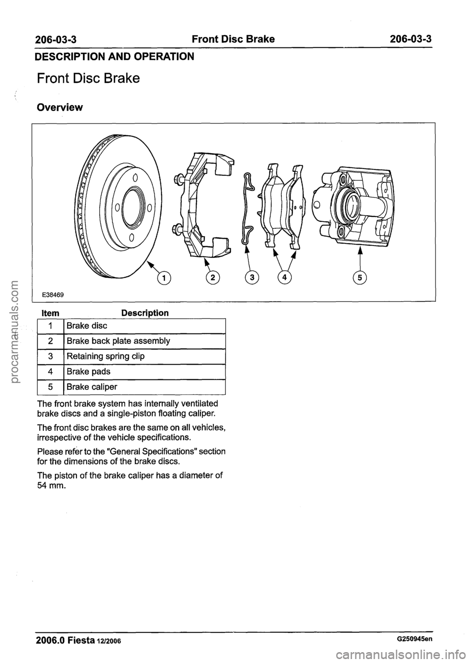
Item Description
i
The front brake system has internally ventilated
brake discs and a single-piston floating caliper.
3
4
5
The front disc brakes are the same on all vehicles,
irrespective of the vehicle specifications.
1
2
Retaining spring clip
Brake pads
Brake caliper
Please refer to the "General Specifications" section
for the dimensions of the brake discs.
Brakedisc
Brake back plate assembly
The piston of the brake caliper has a diameter of
54 mm.
2006.0 Fiesta 1212006 G250945en
procarmanuals.com
Page 267 of 1226
206-0713 Power Brake Actuation 206-0713
DESCRIPTION AND OPERATION
Brake Booster
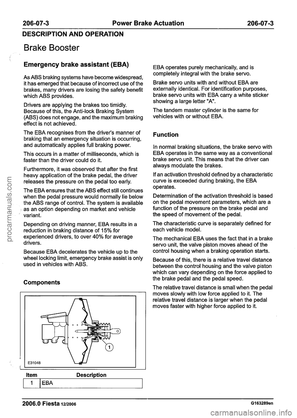
Emergency brake assistant (EBA) EBA operates purely mechanically, and is
completely integral with the brakeservo.
As ABS braking systems have become widespread,
it has emerged that because of incorrect use of the
Brake servo units with and without EBA are
brakes, many drivers are losing the safety benefit externally identical. For identification purposes,
which ABS
~rovides. brake servo units with EBA carry a white sticker I showing a large letter "A. Drivers are applying the brakes too timidly.
Because of this, the Anti-lock Braking System The tandem master cylinder
is the same for
(ABS) does not engage, and the maximum braking
vehicles with or without
effect is not achieved.
The EBA recognises from the driver's manner of
braking that an emergency situation is occurring,
and automatically applies full braking power.
This occurs in a matter of milliseconds, which is
faster than the driver could do it.
Furthermore, it was observed that after the first
heavy application of the brake pedal, the driver
releases the pressure on the pedal too early.
The EBA ensures that the ABS effect still continues
when the pedal pressure would normally lie below
the ABS range of control. The system is available
j as an option depending on market and vehicle
variant.
Function
In normal braking situations, the brake servo with
EBA operates in the same way as a conventional
brake servo unit. This means that the driver can
always modulate the brakes.
If an activation threshold defined by a characteristic
curve is exceeded during braking, the EBA
operates.
Determination of the activation threshold is based
on the pedal movement parameters, which are a
function of the pressure on the brake pedal and
the speed of movement of the pedal.
Depending on driving manner, EBA results in a The characteristic curve
is separately defined for
reduction in braking distance of 15% for each vehicle model.
experienced drivers, to over
40% for average The mechanical EBA uses the fact that in a brake
drivers. servo unit, the valve piston moves ahead of the
Because EBA decelerates the vehicle up to the control housing
when a braking operation starts.
wheel locking limit, emergency brake assist is only Because of this, there is a relative travel distance used in vehicles with ABS.
between the control housing and the valve piston
which can vary depending on the force applied to
Components the brake pedal and the pedal speed.
The relative travel distance is small when the pedal
moves slowly with low force applied to it. The
relative travel distance is larger when the pedal
moves faster with higher force applied to it.
Item Description
-
2006.0 Fiesta 1212006 GI 63289en
procarmanuals.com
Page 277 of 1226

206-09A-3 Anti-Lock Control 206-09A-3
DESCRIPTION AND OPERATION
Anti-Lock Control
Overview
Function
The ABS is a closed loop control system in the
brake system which prevents the wheels from
1 4 1 Ignition lock I situations.
3
1 5 1 Stoplamp switch I
6 ABS warning lamp in the instrument
I 1 cluster
Wheel
speed sensors
In addition to the conventional brake system with
two diagonally split brake circuits, the ABS consists
of an ABS hydraulic unit with integrated control
unit, four wheel sensors and the ABS warning lamp
in the instrument cluster. locking up under
braking and therefore maintains
steerability and driving stability in extreme
Electronic brake force distribution is integrated in
the software of the ABS control unit', which
electronically regulates and optimises the pressure
applied to the wheel brakes on the front and rear
axles in accordance with the operating conditions.
ABS control unit
The ABS control unit continuously compares stored
physical deceleration values with those detected
by the wheel sensors. This allows the lock-up
tendency of each wheel to be detected separately.
If the ABS control unit detects that a wheel is
threatening to lock up, then the corresponding
hydraulic valves in the valve block are either closed
or opened.
The ABS control unit then also passes on the
vehicle speed signal obtained from the wheel sensors to the Powertrain Control Module (PCM).
2006.0 Fiesta 1212oo6 GI 63290en
procarmanuals.com
Page 278 of 1226
206-09A-4 Anti-Lock Control 206-09A-4
DESCRIPTION AND OPERATION
The warning lamp in the instrument cluster is
actuated by the ABS control unit after switching on
the ignition. It remains on up to the end of the ABS
self-test, and is also actuated in the event of
system errors.
It continuously monitors the system for possible
faults and stores these as and when they occur.
The corresponding trouble codes can be
interrogated with the aid of WDS via the DLC
.
The ABS control unit is directly connected via a
diagnostic data link to the DLC.
Valve block
The valve block contains four inlet valves and four
outlet valves. There is one inlet valve and one
outlet valve for each wheel.
When there is no electrical supply the inlet valves
are open and the outlet valves are closed.
The valve block also contains the low-pressure
reservoir and sound damping chambers.
Pump motor
In the event of an ABS intervention the pump motor
ensures that the pressure can be provided to the
regulating channels independently of the brake
master cylinder.
ABS regulating cycle
An ABS regulating cycle has three phases:
Phase
1 - holding pressure
The inlet valve is closed, and the brake pressure
to the wheel brake cannot be increased any
further, even if the actuation pressure (brake
pedal) is increased further.
Phase
2 - pressure reduction
The outlet valve is temporarily opened, and the
brake pressure to the wheel brake is reduced
in a controlled manner.
Phase
3 - pressure build-up
The inlet valve is opened in stages, and the
brake pressure is increased in a controlled
manner to achieve the greatest possible
deceleration.
2006.0 Fiesta 1212006 GI 63290en
procarmanuals.com
Page 279 of 1226
206-0949-5 Anti-Lock Control 206-09A-5 -- -
DESCRIPTION AND OPERATION
Anti-Lock Control
MK70 Anti-lock Brake System (ABS)
The MK70 ABS is similar to the MK60 in
construction and design. The main differences are:
New ABS control unit
New hydraulic lines through a revised valve
block
New wiring harness and electrical connector
(fewer occupied pins)
The MK70 ABS system will be installed from
0512004 in vehicles which only have one ABS
function.
Vehicles with
ESPlBrake Traction Control System
(BTCS) will continue to be equipped with the
MK60.
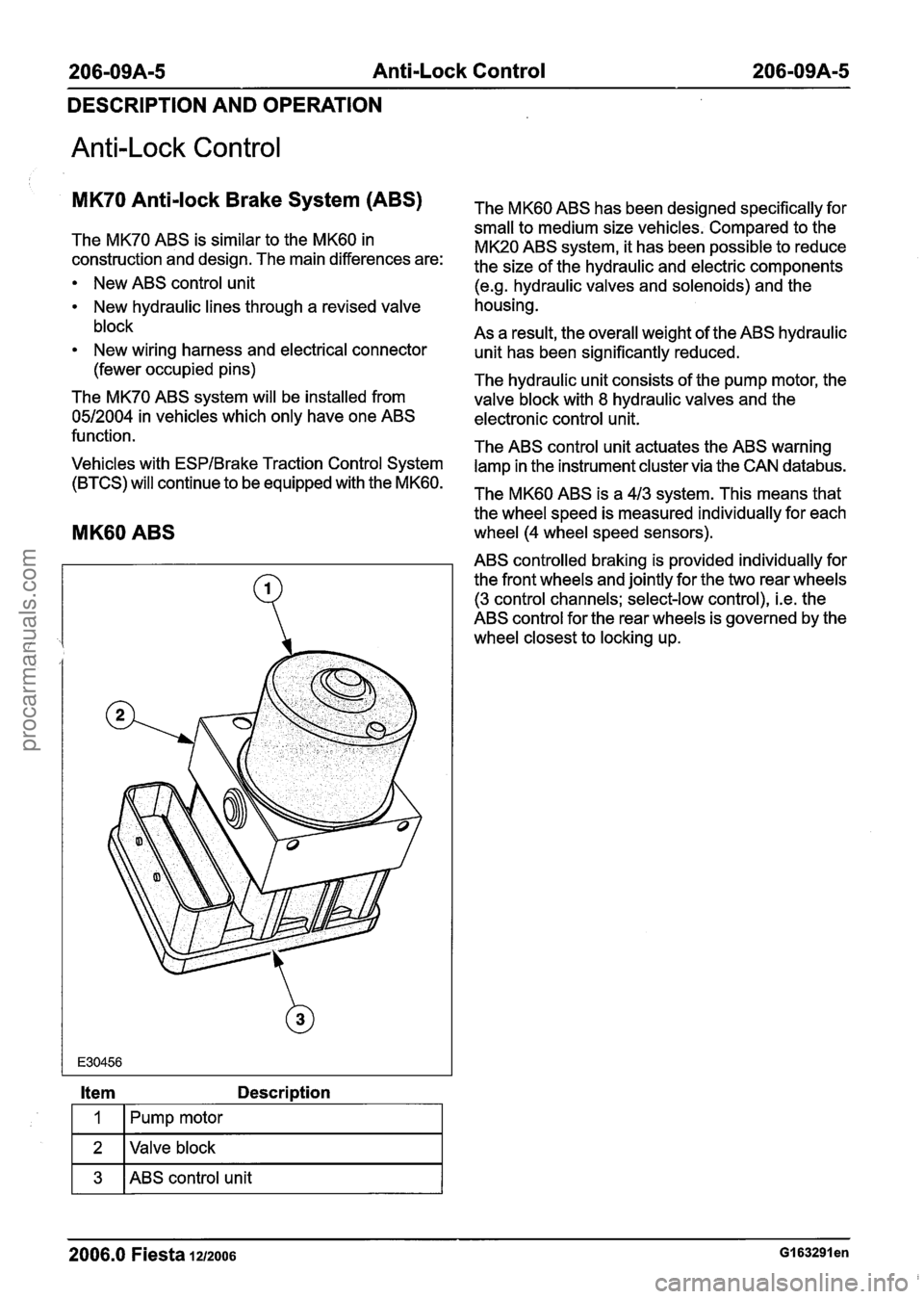
MK60 ABS
Item Description
Fpump motor I
1 2 I Valve block I
1 3 1 ABS control unit I
The MK60 ABS has been designed specifically for
small to medium size vehicles. Compared to the
MK20 ABS system, it has been possible to reduce
the size of the hydraulic and electric components
(e.g. hydraulic valves and solenoids) and the
housing.
As a result, the overall weight of the ABS hydraulic
unit has been significantly reduced.
The hydraulic unit consists of the pump motor, the
valve block with
8 hydraulic valves and the
electronic control unit.
The ABS control unit actuates the ABS warning lamp in the instrument cluster via the CAN
databus.
The MK60 ABS is a 413 system. This means that
the wheel speed is measured individually for each
wheel (4 wheel speed sensors).
ABS controlled braking is provided individually for the front wheels and jointly for the two rear wheels
(3 control channels; select-low control), i.e. the
ABS control for the rear wheels is governed by the
wheel closest to locking up.
- --
2006.0 Fiesta 1212006 GI 63291 en
procarmanuals.com
Page 325 of 1226
211 -00-5 Steering System - General Information 211 -00-5
DIAGNOSIS AND TESTING
Steering System
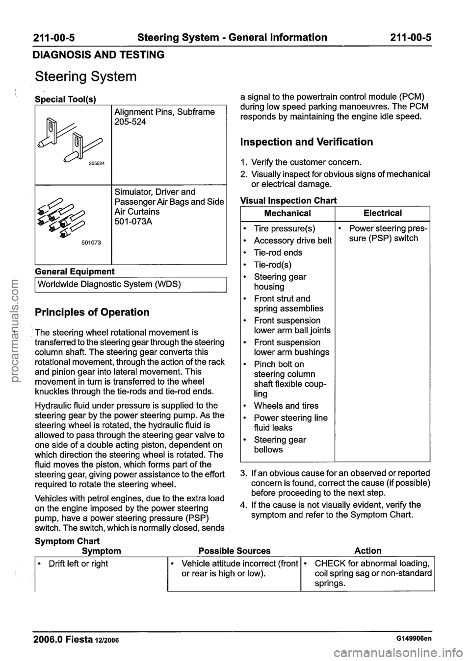
/ Special Tool(s)
Alignment Pins, Subframe
205-524
Simulator, Driver and
passenger ~ir Bags and Side
Air Curtains 50
1 -073A
General Eaui~ment
I Worldwide Diagnostic System (WDS) I
Principles of Operation
The steering wheel rotational movement is
transferred to the steering gear through the steering
column shaft. The steering gear converts this
rotational movement, through the action of the rack
and pinion gear into lateral movement. This
movement in turn is transferred to the wheel
knuckles through the tie-rods and tie-rod ends.
Hydraulic fluid under pressure is supplied to the
steering gear by the power steering pump. As the
steering wheel is rotated, the hydraulic fluid is
allowed to pass through the steering gear valve to
one side of a double acting piston, dependent on
which direction the steering wheel is rotated. The
fluid moves the piston, which forms part of the
steering gear, giving power assistance to the effort
required to rotate the steering wheel.
Vehicles with petrol engines, due to the extra load
on the engine imposed by the power steering
pump, have a power steering pressure (PSP)
switch. The switch, which is normally closed, sends a signal
to the powertrain control module (PCM)
during low speed parking manoeuvres. The PCM
responds by maintaining the engine idle speed.
lnspection and Verification
1. Verify the customer concern.
2. Visually inspect for obvious signs of mechanical
or electrical damage.
Visual lnspection Chart
I Mechanical I Electrical I
Tire pressure(s)
Accessory drive belt
Tie-rod ends
Tie-rod (s)
Steering gear housing
Front strut and
spring assemblies
Front suspension
lower arm ball joints
Front suspension
lower arm bushings
Pinch bolt on
steering column
shaft flexible coup-
ling Power
steering pres-
sure (PSP) switch
Wheels and tires
Power steering line
fluid leaks
Steering gear
bellows
3. If an obvious cause for an observed or reported
concern is found, correct the cause (if possible)
before proceeding to the next step.
4. If the cause is not visually evident, verify the
symptom and refer to the Symptom Chart.
Symptom Chart
Symptom Possible Sources Action
Drift left or right
2006.0 Fiesta 1212006 Gl49906en
Vehicle attitude incorrect (front
or rear is high or low). CHECK for abnormal loading,
coil spring sag or non-standard
springs.
procarmanuals.com
Page 455 of 1226
303-00-33 Engine System - General Information 303-00-33
GENERAL PROCEDURES
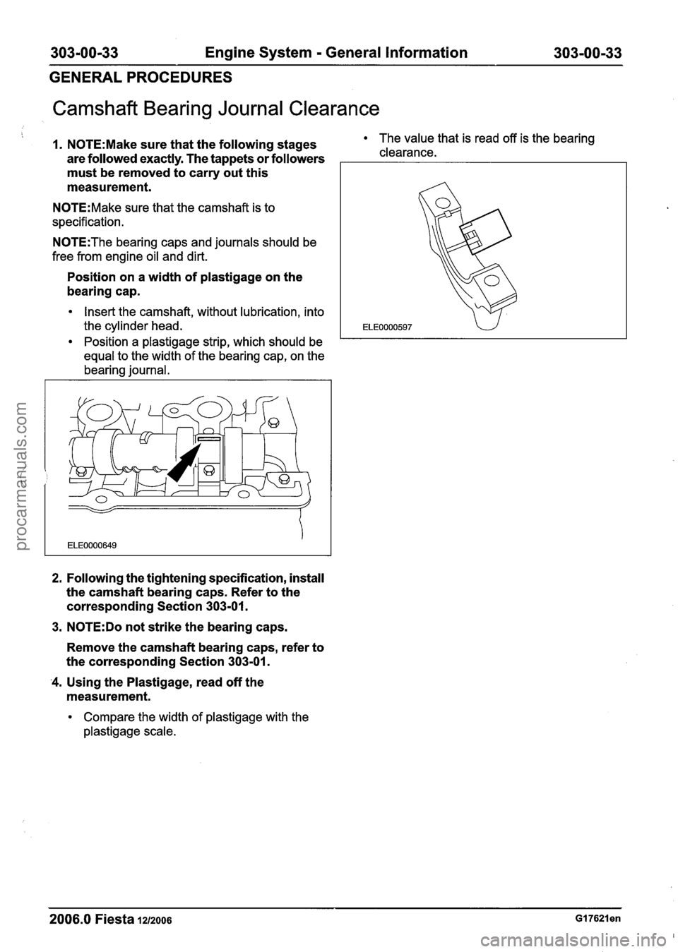
Camshaft Bearing Journal Clearance
1. N0TE:Make sure that the following stages The value that is read off is the bearing
are followed exactly. The tappets or followers clearance.
must be removed to carry out this
measurement.
N0TE:Make sure that the camshaft is to
specification.
N0TE:The bearing caps and journals should be
free from engine oil and dirt.
Position on a width of plastigage on the
bearing cap.
Insert the camshaft, without lubrication, into
the cylinder head.
Position
a plastigage strip, which should be
equal to the width of the bearing cap, on the
bearing journal.
2. Following the tightening specification, install
the camshaft bearing caps. Refer to the
corresponding Section 303-01.
3.
N0TE:Do not strike the bearing caps.
Remove the camshaft bearing caps, refer to
the corresponding Section 303-01.
'4. Using the Plastigage, read off the
measurement.
Compare the width of plastigage with the
plastigage scale.
2006.0 Fiesta 1212006
procarmanuals.com