ESP FORD FIESTA 2007 Service Manual
[x] Cancel search | Manufacturer: FORD, Model Year: 2007, Model line: FIESTA, Model: FORD FIESTA 2007Pages: 1226, PDF Size: 61.26 MB
Page 1218 of 1226

Acceleration Control - 1.3L Duratec-8V
(Rocam)llI25L Duratec-1 6V (Sigma)llI4L
31 0-02A-4 Duratec-1 6V (Sigma)/l .6L
Duratec-1 6V (Sigma)
31 0-02A-4
DIAGNOSIS AND TESTING
Electronic Throttle Body
The electronic throttle body is similar to a
mechanical throttle body used on a cable
accelerator system. Instead of the cable moving
the throttle plate open and closed, it uses an
internal electrical motor that is driven by the PCM.
The electronic throttle body has two sensors that
measure the throttle plate position. The sensors
output a voltage to the PCM corresponding to the
plate position.
When the electronic throttle body motor is not in
use, the throttle plate sits slightly open in a default
position (not idle position). This position is
maintained by two internal springs. One acts
upwards and one downwards. Screws on the
electronic throttle body will not adjust the idle
speed, the idle speed is controlled by the PCM.
PCM
The PCM reads the voltage from the pedal and
converts this signal into a driver request. The driver
request is realized by opening or closing the throttle
body. To do this, the PCM increases or decreases
power to the electronic throttle body motor. The
PCM then checks the signal from the electronic
throttle body throttle position (TP) sensor, to make
sure that the requested position has been
achieved. The PCM also monitors all the sensors
to make sure that the system is functioning as
expected. All electronic accelerator control system
faults will be detected by the PCM and set a
diagnostic trouble code (DTC) which triggers the
electronic accelerator control fail message
accordingly. For safety reasons, some faults will
also reduce the vehicle performance.
Diagnostic Trouble Codes
Description
When a component electrical error is set it means
that the PCM is not receiving the expected signal.
This means that the concern may lie between the
component and the PCM. All wiring and electrical
connectors should be checked before a new
component is installed. Also note that general
vehicle electrical issues can have an effect on other
systems. Battery voltage and relay concerns should
be rectified first.
Accelerator Pedal Codes
These are the DTCs relating to the pedal circuit.
They do not imply necessarily that the accelerator
pedal is at fault, but it will in any case relate to area
"A (see system overview).
P2120 - Accelerator pedal sensor 1 electrical
error
P2122 - Accelerator pedal sensor I electrical
error short to ground or open circuit
P2123 - Accelerator pedal sensor I electrical
error short to battery
P2125 - Accelerator pedal sensor 2 electrical
error
P2127 - Accelerator pedal sensor 2 electrical
error short to ground or open circuit
P2128 - Accelerator pedal sensor 2 electrical
error short to battery
P2138 - Accelerator pedal sensor 1 & 2 ratio
error
Electronic Throttle Body Circuit Codes
These are the DTCs relating to the electronic
throttle body circuit. They do not imply necessarily
( ,)
that the electronic throttle body is the concern, but
it will in any case relate to area "B" (see system
overview).
PO1 20 - Throttle position (TP) sensor 1
electrical error
PO122 - (TP) sensor 1 electrical error short to
ground
PO123 - (TP) sensor 1 electrical error short to
battery or line break
PO220 - (TP) sensor 2 electrical error
PO222 - (TP) sensor 2 electrical error short to
ground or open circuit
PO223 - (TP) sensor 2 electrical error short to
battery
P2135 - (TP) sensor ratio error
P21
I 9 - Throttle plate convergence error
- This is when the throttle plate has not moved
to the requested position in the required time.
This could be caused by the following:
- The electronic throttle body motor is not
receiving the necessary voltage. Check the
--
electronic throttle body motor wiring. The ( PCM is not receiving the correct throttle plate '
position signal from the electronic throttle
body. Check the TP sensor wiring from the
2006.0 Fiesta 1212006 G356253en
procarmanuals.com
Page 1224 of 1226

31 0-02B-2 Acceleration Control - 2.OL Duratec-HE (M14) 31 0-02B-2
DESCRIPTION AND OPERATION
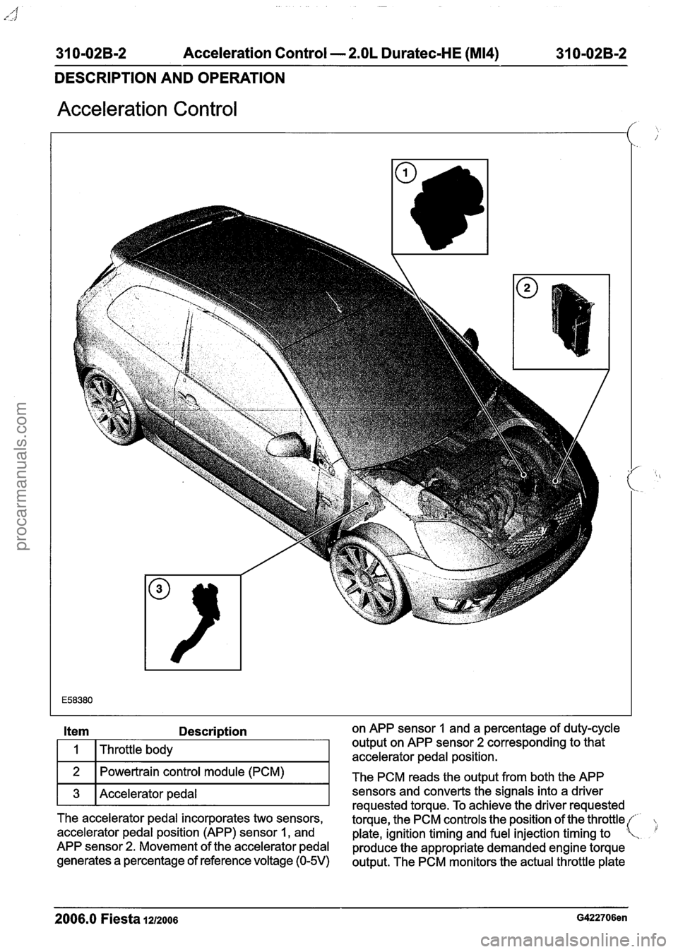
Acceleration Control
Description on APP sensor 1 and a percentage of duty-cycle
Throttle body output on
APP sensor
2 corresponding to that
accelerator pedal position.
Powertrain control module (PCM)
The PCM reads the output from both the APP
3 Accelerator pedal T sensors requested and torque. converts To achieve the signals the driver into a requested driver
The accelerator pedal incorporates two sensors,
torque, the PCM controls the position of the throttle(
accelerator pedal position (APP) sensor
1, and
plate, ignition timing and fuel injection timing to .
APP sensor 2. Movement of the accelerator pedal
produce the appropriate demanded engine torque
generates a
percentage of reference voltage (0-5V) output. The PCM monitors the actual throttle plate
2006.0 Fiesta 1212006 G422706en
procarmanuals.com
Page 1225 of 1226

31 0-02B-3 Acceleration Control - 2.OL Duratec-HE (M14) 31 0-02B-3
DESCRIPTION AND OPERATION
position from the throttle position (TP) sensors to
make sure that the requested position has been
lachieved .
N0TE:Do not install a new accelerator pedal
unless a relevant accelerator pedal DTC has been
stored in the PCM. For additional information refer
to WDS.
The accelerator pedal is a non-serviceable
component which cannot be adjusted and therefore
must not be disassembled or tampered with.
The throttle body is directly controlled by the PCM
and has two TP sensors, TP
1 and TP 2. The TP
sensors output a voltage to the PCM that
corresponds to the actual throttle plate position.
When the throttle body motor is not being powered
up, the throttle plate sits open at approximately 8
degrees from the closed in-bore position. This
position (also referred to as the default position),
is maintained within the throttle body by two internal
compression return springs acting in opposing
directions, these springs are a non-serviceable
item.
The PCM continuously monitors both APP sensors
and both TP sensors to make sure that the system
,is functioning as expected. All acceleration control
( 'system concerns will be detected by the PCM and
the appropriate diagnostic trouble code (DTC) set.
The malfunction indicator lamp (MIL), located in
the instrument cluster will also be illuminated if a
concern is apparent. As the acceleration control
system is of a safety-critical nature, it is possible
that a system concern will result in a reduced
vehicle performance and a DTC stored in the PCM.
For additional information refer to WDS.
2006.0 Fiesta 1212006 G422706en
procarmanuals.com