ESP FORD FIESTA 2007 Owner's Guide
[x] Cancel search | Manufacturer: FORD, Model Year: 2007, Model line: FIESTA, Model: FORD FIESTA 2007Pages: 1226, PDF Size: 61.26 MB
Page 992 of 1226
Automatic Transmission/Transaxle -
Vehicles With: 4-Speed Automatic
307-01 -32 Transmission
(AW81-40) 307-01 -32
DESCRIPTION AND OPERATION
This is influenced by the following variables:
Engine speed,
Engine load,
Transmission input speed,
Vehicle speed.
The following are actuated:
PCM (torque reduction request signal via the
CAN databus).
Pressure control during gearshifts
In order to ensure that the engagement of the
clutches and brakes is as judder-free as possible,
the main line pressure is reduced during gearshifts.
This is influenced by the following variables:
Enginespeed,
Engine load,
Transmission input speed,
Vehicle speed.
The following are actuated:
Main regulating valve.
Shift timing adaptation during upshifts
In order to ensure that the engagement of the
clutches and brakes is as judder-free as possible,
the timing of the gearshift processes is monitored
during upshifts.
In the event of any discrepancy from the target
values, the main line pressure is adapted
accordingly during the next gearshift.
The shift timing adaptation during upshifts is only
active at transmission fluid temperatures between
50
"C and 120 "C.
This is influenced by the following variables:
Engine load,
Accelerator pedal position,
Transmission input speed,
Vehicle speed,
Transmission fluid temperature,
Selector lever position.
The following are actuated:
Main regulating valve.
Shift timing adaptation during shifts from
3rd to 4th gear
The shift from 3rd gear into 4th gear is the only
gearshift during which a clutch is disengaged and
a brake is engaged simultaneously.
In order to control the synchronized switching of
the two components as exactly as possible, the
shifl timing solenoid valve is actuated accordingly.
In order to ensure that this particular gearshift is
performed as judder-free as possible throughout
the service life of the transmission, the gearshift is
monitored by the two rotational speed sensors and
the actuation of the shift timing solenoid valve is
adapted accordingly.
The shift timing adaptation for gearshifts from 3rd
gear into 4th gear is only active at transmission
fluid temperatures between 30
"C and 120 "C.
This is influenced by the following variables:
Engine load,
Accelerator pedal position,
Transmission input speed,
Vehicle speed,
Transmission fluid temperature,
Selector lever position.
The following are actuated:
Shift timing solenoid valve.
Shift timing adaptation during shifts from
4th to 3rd gear
The shift from 4th gear into 3rd gear is the only
gearshift during which a brake is disengaged and
a clutch is engaged simultaneously.
In order to control the engagement of the clutch as
precisely as possible, the main regulating valve is
actuated accordingly in order to build up the
actuating pressure at exactly the right time.
In order to ensure that this particular gearshift is
performed as judder-free as possible throughout
the service life of the transmission, the gearshift is
monitored by the two rotational speed sensors and
the actuation of the main regulating valve is
adapted accordingly.
The shift timing adaptation for gearshifts from 4th
-
gear into 3rd gear is only active at transmission (
fluid temperatures between 20 "C and 120 "C. .
2006.0 Fiesta 1212006 G380530en
procarmanuals.com
Page 993 of 1226
Automatic Transmission/Transaxle -
Vehicles With: 4Speed Automatic
307-01 -33 Transmission (AW81-40) 307-01 -33
DESCRIPTION AND OPERATION
This is influenced by the following variables: Vehicle
speed,
Engine load, Transmission fluid temperature.
Accelerator pedal position, The following are actuated:
Transmission input speed, SSA shift solenoid valve,
Vehicle speed,
Transmission fluid temperature,
Selector lever position.
The
following are actuated:
Main
regulating valve.
Reverse gear safety strategy
SSB shift solenoid valve.
Torque reduction when pulling away
In order to protect the clutches against excessively
high torque when pulling away, the PCM reduces
the engine torque in response to a request from
the transmission
control.
If the accelerator pedal is depressed while the
The transmission control unit prevents shifts into vehicle is pulling away, then the transmission reverse gear while the vehicle is driving forwards, control unit sends a corresponding signal as otherwise serious transmission damage can be requesting a torque reduction via the CAN databus. caused.
The reverse gear safety strategy is active when This
is influenced by the
following variables:
reverse gear is engaged with the selector lever at ' Selector lever position,
vehicle speeds in excess of 11 kmlh. Accelerator pedal position,
In this
case the transmission control unit actuates ' Engine speed,
the shift timing solenoid valve, as a result of which Transmission input speed,
the actuating pressure does not reach the reverse
. Vehicle speed. gear clutch or the reverse gear brake.
The following are actuated:
The reverse gear safety strategy is deactivated
PCM (torque reduction request signal via the
when the vehicle speed is below 9 kmlh. The
actuating pressure can then reach the reverse gear CAN
databus).
clutch and the reverse gear brake and the gearshift
into reverse gear is performed.
Selector lever positions
This is influenced by the following variables:
Vehicle speed,
Selector lever position.
The
following are actuated:
Shift timing solenoid valve.
Selector lever position "P"
No gear is engaged in selector lever position "P".
The parking
pawl is engaged manually via the
selector lever cable and the selector shaft.
Avoidance of gearshift judder during
engagement of a transmission range Selector
lever position "R"
In order to prevent gearshift judder when moving The reverse gear is eWaged in selector lever
the selector lever from N to D, the transmission position "R.
control unit initially shifts into
2nd gear instead of
1 st gear, and then immediately shifts back into I st
gear before the gearshift process is finished. Selector lever position "N"
This reduces the amount of gearshift judder during No gear is engaged in selector lever position WNW. engagement of a forward drive range.
The powertrain is not blocked. This is influenced by the following variables:
Selector lever position,
Accelerator pedal position,
Transmission input speed,
2006.0 Fiesta 1212006 G380530en
procarmanuals.com
Page 999 of 1226
Automatic Transmission/Transaxle -
Vehicles With: 4-Speed Automatic
307-01 -39 Transmission (AW81-40) 307-01 -39
DESCRIPTION AND OPERATION
TFT sensor Overdrive switch
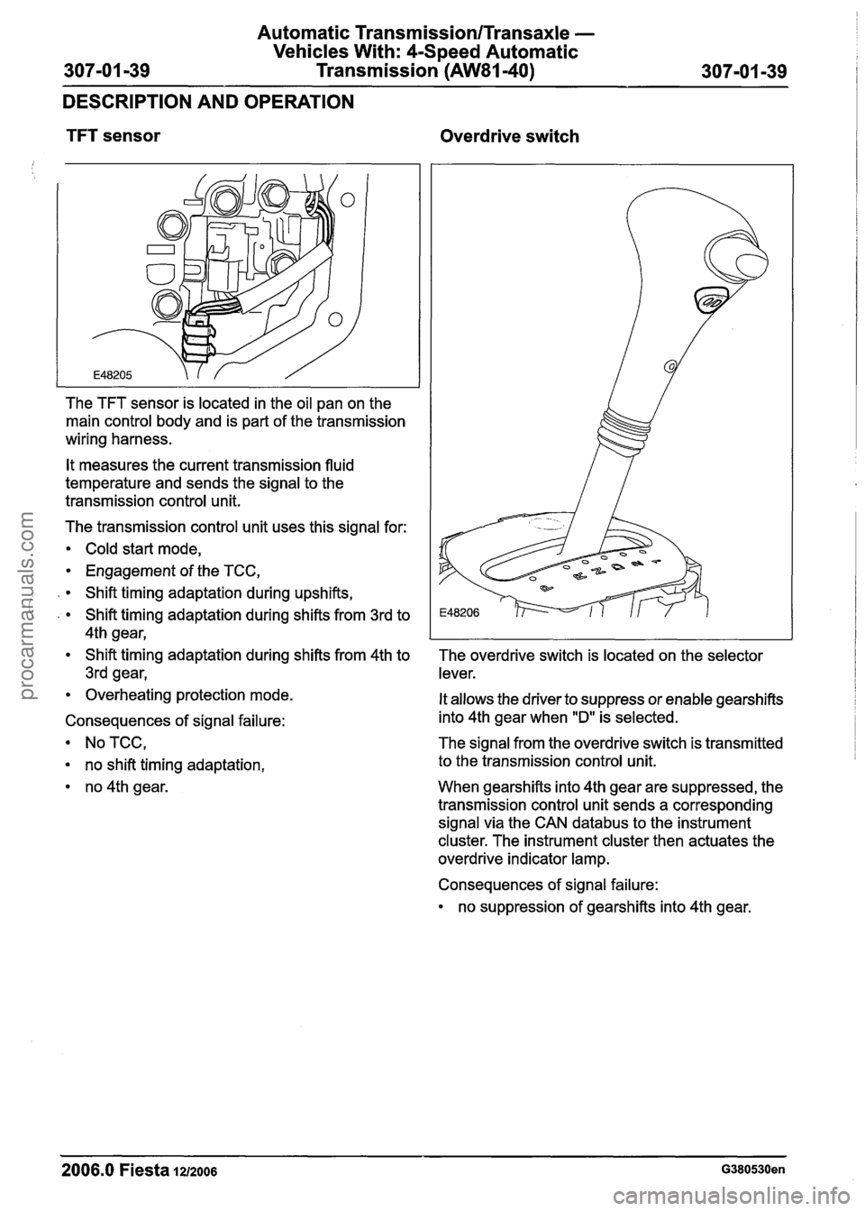
The TFT sensor is located in the oil pan on the
main control body and is part of the transmission
wiring harness.
It measures the current transmission fluid
temperature and sends the signal to the
transmission control unit.
The transmission control unit uses this signal for:
Cold start mode,
Engagement of the TCC,
Shift timing adaptation during upshifts,
' , Shift timing adaptation during shifts from 3rd to
4th gear,
Shift timing adaptation during shifts from 4th to
3rd gear,
Overheating protection mode.
Consequences of signal failure:
NoTCC,
no shift timing adaptation,
no 4th gear. The overdrive switch
is located on the selector
lever.
It allows the driver to suppress or enable gearshifts
into 4th gear when
"D" is selected.
The signal from the overdrive switch is transmitted
to the transmission control unit.
When gearshifts into 4th gear are suppressed, the
transmission control unit sends a corresponding
signal via the CAN
databus to the instrument
cluster. The instrument cluster then actuates the
overdrive indicator lamp.
Consequences of signal failure:
no suppression of gearshifts into 4th gear.
2006.0 Fiesta 1212006 G380530en
procarmanuals.com
Page 1000 of 1226
Automatic Transmission/Transaxle -
Vehicles With: 4-Speed Automatic
307-01 -40 Transmission (AW81-40)
307-01 -40
DESCRIPTION AND
OPEMION
Driver's side door ajar switch
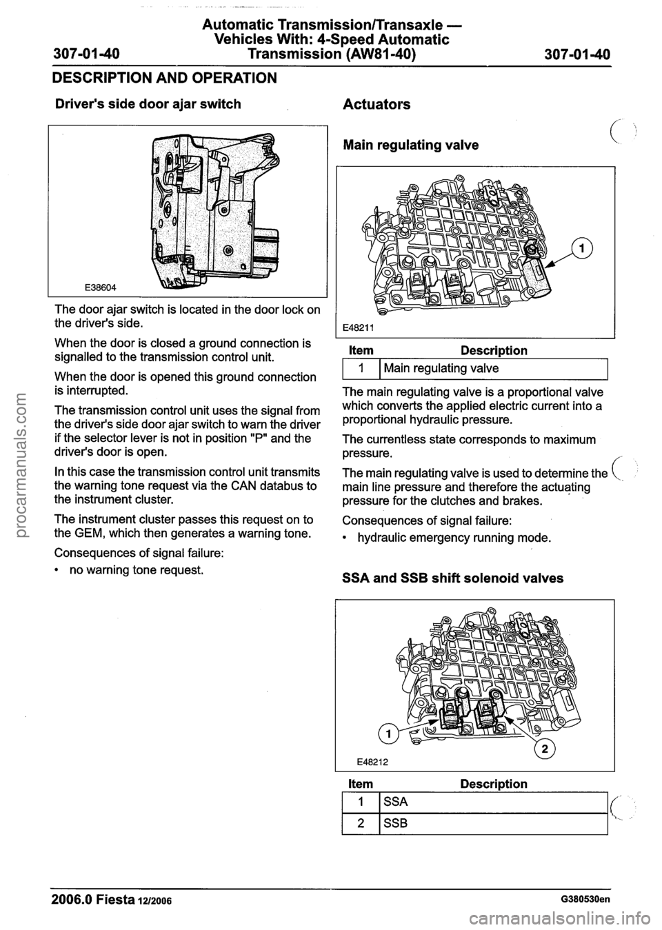
The door ajar switch is located in the door lock on
the driver's side.
When the door is closed a ground connection is
signalled to the transmission control unit.
When the door is opened this ground connection
is interrupted.
The transmission control unit uses the signal from
the driver's side door ajar switch to warn the driver
if the selector lever is not in position
"P" and the
driver's door is open.
In this case the transmission control unit transmits
the warning tone request via the CAN
databus to
the instrument cluster.
The instrument cluster passes this request on to
the GEM, which then generates a warning tone.
Consequences of signal failure:
no warning tone request.
Actuators
Main regulating valve
Item Description
I 1 I Main regulating valve I
The main regulating valve is a proportional valve
which converts the applied electric current into a
proportional hydraulic pressure.
The currentless state corresponds to maximum
pressure.
/
The main regulating valve is used to determine the
main line pressure and therefore the actuating
pressure for the clutches and brakes.
Consequences of signal failure:
hydraulic emergency running mode.
SSA and SSB shift solenoid valves
Item Description
2006.0 Fiesta 1212006 G380530en
1
2
SSA
SSB
(- t..
procarmanuals.com
Page 1049 of 1226

Automatic Transmission/Transaxle External
Controls -Vehicles With: 4-Speed Automatic
307-05-5 Transmission (AW81-40) 307-05-5
GENERAL PROCEDURES
Selector Lever Cable Adjustment
Adjustment Move the transaxle selector lever to the "D"
1. Shift the selector lever to the "D" (DRIVE) (DRIVE) position.
position.
2. Raise and support the vehicle.
5. N0TE:Ensure that the selector lever cable
adjustment mechanism is locked.
- -
For additional information, refer to: Lifting Press
in the selector lever cable adjustment
(1 00-02 Jacking and Lifting, Description mechanism
locking clip fully.
and Operation).
3. Release the selector lever cable adjustment
1, ' mechanism locking clip.
6. Lower the vehicle.
7. Start the engine and move the selector lever
through all the gear positions. Wait until each
4. N0TE:ln the "D" (DRIVE) position the gear engages
when moving through the gear
transmission range (TR) sensor locking positions.
washer pointer will be aligned with the line
8. Check that the selector lever position
scribed on the TR sensor body. indicator corresponds to the position of the
selector lever, repeat the adjustment
procedure if necessary.
9. Move the selector lever into the "P" (PARK)
position and switch off the engine.
2006.0 Fiesta 1212006 G388012en
procarmanuals.com
Page 1076 of 1226
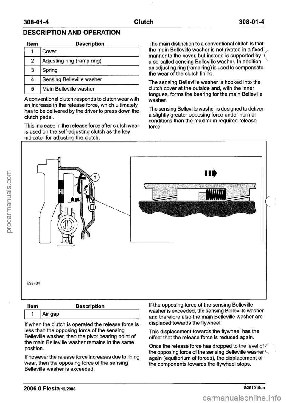
308-01 4 Clutch 308-01 -4
DESCRIPTION AND OPERATION
Item Description
I I 1 Cover I
1 2 I Adjusting ring (ramp ring) I
1 3 1 Spring I
1 4 1 Sensing Belleville washer I
r5 1 Main Belleville washer I
A conventional clutch responds to clutch wear with
an increase in the release force, which ultimately
has to be delivered by the driver to press down the
clutch pedal.
This increase in the release force after clutch wear
is used on the self-adjusting clutch as the key
indicator for adjusting the clutch. The main
distinction to a conventional clutch is that
the main Belleville washer is not riveted in a fixed
-
manner to the cover, but instead is supported by (
a so-called sensing Belleville washer. In addition
an adjusting ring (ramp ring) is used to compensate
the wear of the clutch lining.
The sensing Belleville washer is hooked into the
clutch cover at the outside and, with the inner
tongues, forms the bearing for the main Belleville
washer.
The sensing Belleville washer is designed to deliver
a slightly greater opposing force under normal
conditions than the maximum required release
force.
Item Description
If when the clutch is operated the release force is
less than the opposing force of the sensing
Belleville washer, then the pivot bearing point of
the main Belleville washer remains in the same
position.
If however the release force increases due to lining
wear, then the opposing force of the sensing
Belleville washer is exceeded. If the
opposing force of the sensing Belleville
washer is exceeded, the sensing Belleville washer
and therefore also the main Belleville washer are
displaced towards the flywheel.
This displacement towards the flywheel has the
effect that the release force is reduced again.
Once the release force has dropped to the level of
the opposing force of the sensing Belleville washer
again (equilibrium of forces), the displacement of
the components towards the flywheel stops.
2006.0 Fiesta lazoos ~251010en
procarmanuals.com
Page 1100 of 1226
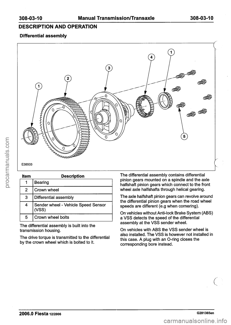
308-03-1 0 Manual Transmission/Transaxle 308-03-1 0
DESCRIPTION AND OPERATION
Differential assembly
Item Description
I 1 1 Bearing I
1 2 1 Crown wheel I
1 3 1 Differential assembly I
4 Sender wheel - Vehicle Speed Sensor
I I (VSS)
The differential assembly is built into the
transmission housing.
The drive torque is transmitted to the differential
by the crown wheel which is bolted to it. The differential
assembly contains differential
pinion gears mounted on a spindle and the axle
halfshaft pinion gears which connect to the front
wheel axle halfshafts through helical gearing.
The axle halfshaft pinion gears can revolve around
the differential pinion gears when the road wheel
speeds are different
(e.g when cornering).
On vehicles without Anti-lock Brake System (ABS)
a VSS detects the speed of the differential
assembly at the VSS sender wheel.
On vehicles with ABS the VSS sender wheel is
also installed. The VSS is however not installed in
this case. A plug with an O-ring closes the
corresponding bore instead.
2006.0 Fiesta la2006 G281365en
procarmanuals.com
Page 1102 of 1226
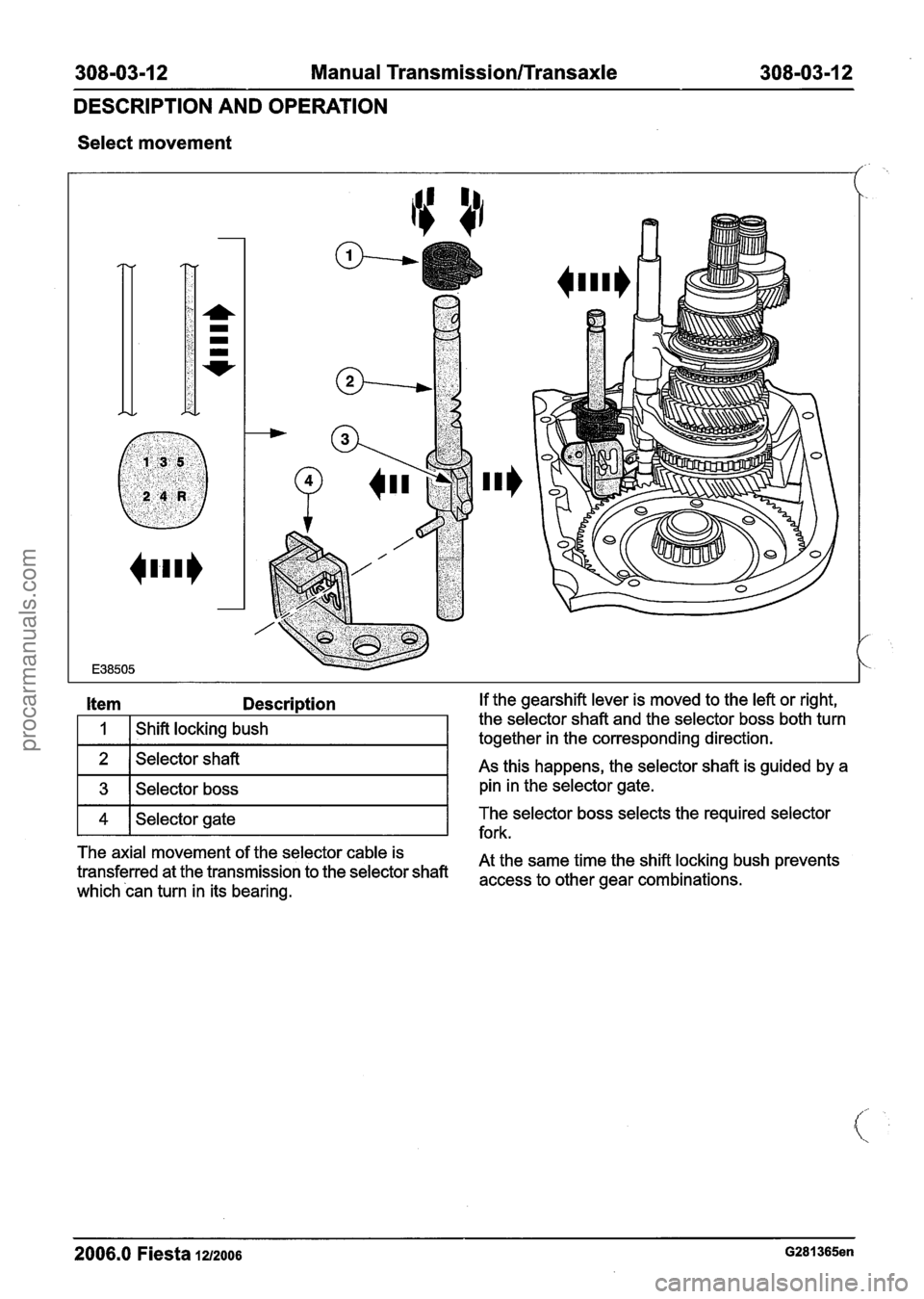
308-03-1 2 Manual Transmission/Transaxle 308-03-1 2
DESCRIPTION AND OPERATION
Select movement
/
Item Description If the gearshift lever is moved to the left or right,
1
2
3
The axial movement of the selector cable is
At the same time the shift locking bush prevents
transferred at the transmission to the selector shaft
access to other gear combinations~ which can turn in its bearing.
Shift locking
bush
4
2006.0 Fiesta 1212006 G281365en
the selector shaft and the selector boss both turn
together in the corresponding direction.
Selector shaft
Selector boss As this
happens, the selector shaft is guided by a
pin in the selector gate.
fork.
Selector gate
The
selector boss selects the required selector
procarmanuals.com
Page 1168 of 1226
Manual Transmission/Transaxle External
308-0614 Controls 308-06-4
DESCRIPTION AND OPERATION
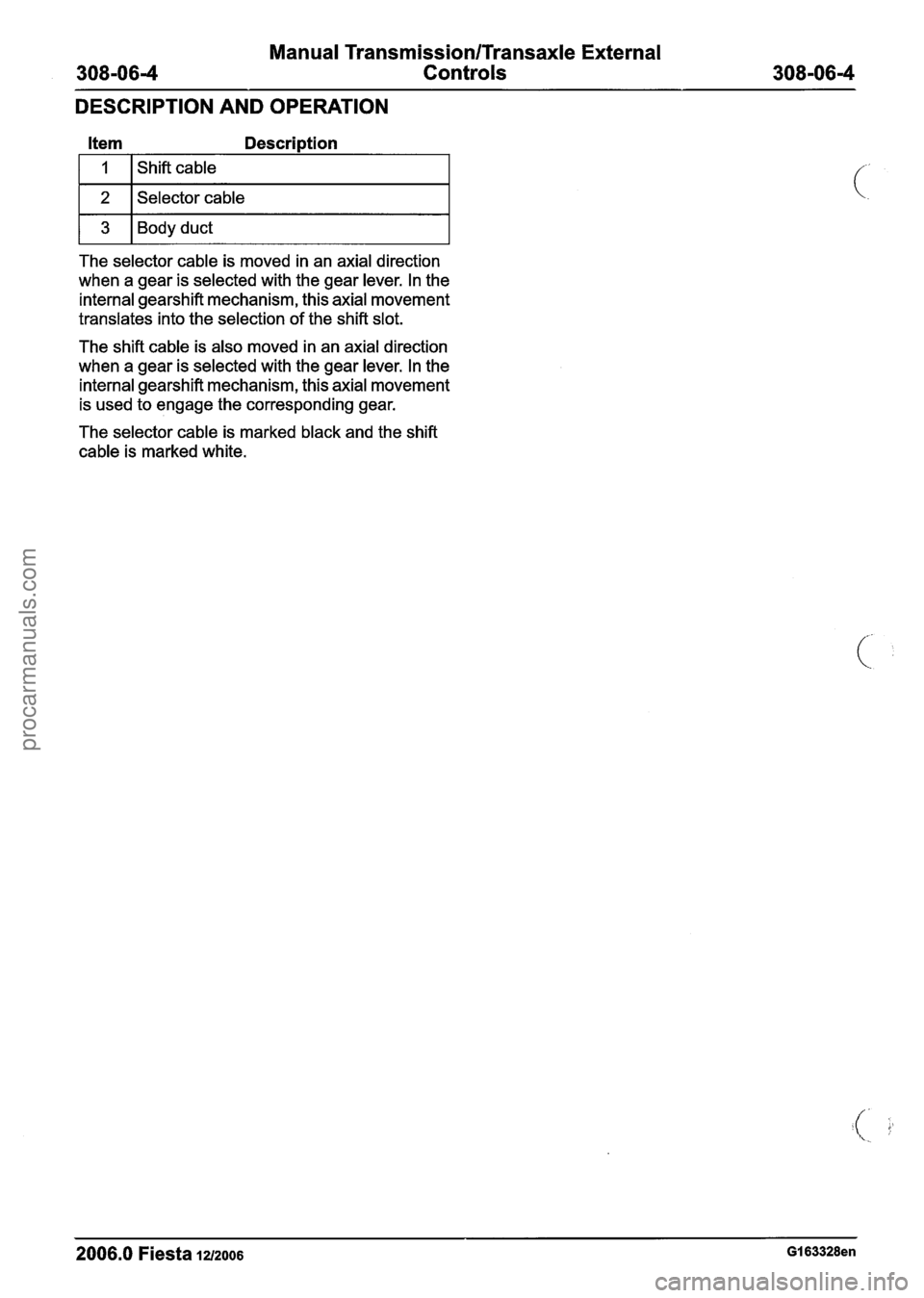
Item Description
1 2 1 Selector cable I
1 3 1 Body duct I
The selector cable is moved in an axial direction
when a gear is selected with the gear lever. In the
internal gearshift mechanism, this axial movement
translates into the selection of the shift slot.
The shift cable is also moved in an axial direction
when a gear is selected with the gear lever. In the
internal gearshift mechanism, this axial movement
is used to engage the corresponding gear.
The selector cable is marked black and the shift
cable is marked white.
2006.0 Fiesta 1212006 GI 63328en
procarmanuals.com
Page 1217 of 1226
Acceleration Control - I .3L Duratec-8V
(Rocam)llI25L Duratec-I 6V (Sigma)ll.4L
Duratec-1 6V (Sigma)ll .6L Duratec-1 6V (Sigma)
DIAGNOSIS AND TESTING
Acceleration Control
Principles of Operation
System Overview
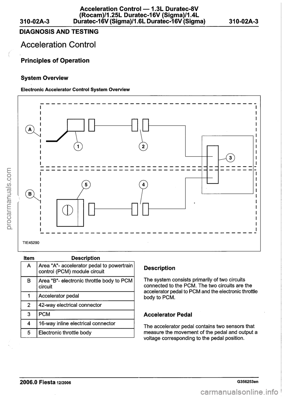
Electronic Accelerator Control System Overview
Item Description
A Area "A- accelerator pedal
to powertrain
1 I control (PCM) module circuit Description
B Area "B"- electronic throttle body to PCM
I I circuit
I 1 I Accelerator pedal I
The system consists primarily of two circuits
connected to the PCM. The two circuits are the
accelerator pedal to PCM and the electronic throttle
body to PCM.
1 3 ~PCM I Accelerator Pedal
2006.0 Fiesta 1212006 G356253en
4
5
voltage corresponding to the pedal position.
16-way
inline electrical connector
Electronic throttle body The accelerator pedal contains two sensors
that
measure the movement of the pedal and output a
procarmanuals.com