section 4 FORD FIESTA 2007 Owner's Guide
[x] Cancel search | Manufacturer: FORD, Model Year: 2007, Model line: FIESTA, Model: FORD FIESTA 2007Pages: 1226, PDF Size: 61.26 MB
Page 127 of 1226
![FORD FIESTA 2007 Owners Guide
204-02-5 Rear Suspension 204-02-5
DIAGNOSIS AND TESTING
Rear Suspension
I . REFER to Section 204-00 [Suspension System -
General Information].
2006.0 Fiesta 1212006 GI 7411 en
procarmanuals. FORD FIESTA 2007 Owners Guide
204-02-5 Rear Suspension 204-02-5
DIAGNOSIS AND TESTING
Rear Suspension
I . REFER to Section 204-00 [Suspension System -
General Information].
2006.0 Fiesta 1212006 GI 7411 en
procarmanuals.](/img/11/56936/w960_56936-126.png)
204-02-5 Rear Suspension 204-02-5
DIAGNOSIS AND TESTING
Rear Suspension
I ' . REFER to Section 204-00 [Suspension System -
General Information].
2006.0 Fiesta 1212006 GI 7411 en
procarmanuals.com
Page 128 of 1226
204-02-6 Rear Suspension 204-02-6
REMOVAL AND INSTALLATION
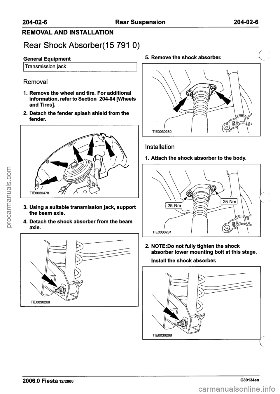
Rear Shock Absorber(l5 791 0)
General Equipment 5. Remove the shock absorber.
I Transmission jack I
Removal
1. Remove the wheel and tire. For additional
information, refer to Section
204-04 [Wheels
and Tires].
2. Detach the fender splash shield from the
fender.
3. Using a suitable transmission jack, support
the beam axle.
4. Detach the shock absorber from the beam
axle.
Installation
I. Attach the shock absorber to the body.
2. N0TE:Do not fully tighten the shock
absorber lower mounting bolt at this stage.
Install the shock absorber.
2006.0 Fiesta lu2006 G89134en
procarmanuals.com
Page 129 of 1226
204-02-7 Rear Suspension 204-02-7
REMOVAL AND INSTALLATION
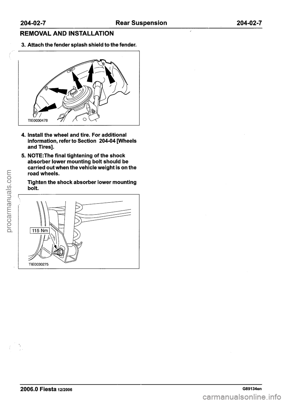
3. Attach the fender splash shield to the fender.
4. Install the wheel and tire. For additional
information, refer to Section
204-04 [Wheels
and Tires].
5. N0TE:The final tightening of the shock
absorber lower mounting bolt should be
carried out when the vehicle weight is on the
road wheels.
Tighten the shock absorber lower mounting
bolt.
2006.0 Fiesta 12/2006 G89134en
procarmanuals.com
Page 130 of 1226
204-0218 Rear Suspension 204-02-8
REMOVAL AND INSTALLATION
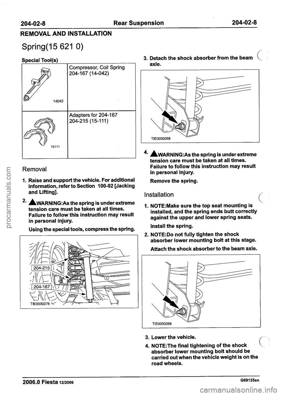
Special Tool(s) I I 3. Detach the shock absorber from the beam t,.
axle.
I I 1 4u AWARNING:A~ the spring is under extreme
tension care must
be taken at all times.
Removal Failure to follow this instruction may result
in personal injury.
1. Raise and support the vehicle. For additional
Remove the spring.
information, refer to Section
100-02 [Jacking
and Lifting].
Installation
2mA~~~~~~~:~~the~~ringis~nderextreme ~~~~~~:~~~~~~~~t~~t~~~~~tmo~~t~n~i~ (.
tension care must be taken at all times.
Failure to follow this instruction may result installed,
and the spring ends butt correctly
against the upper and lower spring seats.
in personal injury.
Using the special tools, compress the spring. Install
the spring.
2. N0TE:Do not fully tighten the shock
absorber lower mounting bolt at this stage.
Attach the shock absorber to the beam axle.
3. Lower the vehicle.
4. N0TE:The final tightening of the shock
absorber lower mounting bolt should be
carried out when the vehicle weight is on the
road wheels.
2006.0 Fiesta 1212006 G89135en
procarmanuals.com
Page 145 of 1226

204-04-1 Wheels and Tires 204-04-1
SECTION 204-04 Wheels and Tires
VEHICLE APPLICATION:2006.0 Fiesta
CONTENTS PAGE
SPECIFICATIONS
Specifications.. ........................................................................\
............................................ 204-04-2
DIAGNOSIS AND TESTING
Wheels and Tires ........................................................................\
........................................ 204-04-3
Inspection and Verification
........................................................................\
..................... 204-04-3
Symptom Chart
........................................................................\
...................................... 204-04-4
REMOVAL AND INSTALLATION
Wheel and Tire ........................................................................\
........................................... 204-04-8
procarmanuals.com
Page 148 of 1226
204-0414 Wheels and Tires 204-04-4
DIAGNOSIS AND TESTING
Engine Speed Sensitive A thumping noise usually means that the tire is flat
or has soft spots making a noise as they slap the
This means that the vibration occurs at varying
roadway. Tire whine can be distinguished from axle
vehicle speeds when a different transmission gear
noise. Tire whine remains the same over a range
is selected. It can sometimes be isolated by
of speeds.
increasing Or decreasing engine with the A complete road test procedure is described in transmission in NEUTRAL or by stall testing with Section the transmission in gear. If the condition is engine
speed sensitive, the-cause is probably not related
REFER to: Noise, Vibration and Harshness (NVH)
to the tires. (1
00-04 Noise, Vibration and Harshness,
If the road test indicates that there is tire whine, Diagnosis and
Testing).
but no shake or vibration, the noise originates with
the contact between the tire and the road surface.
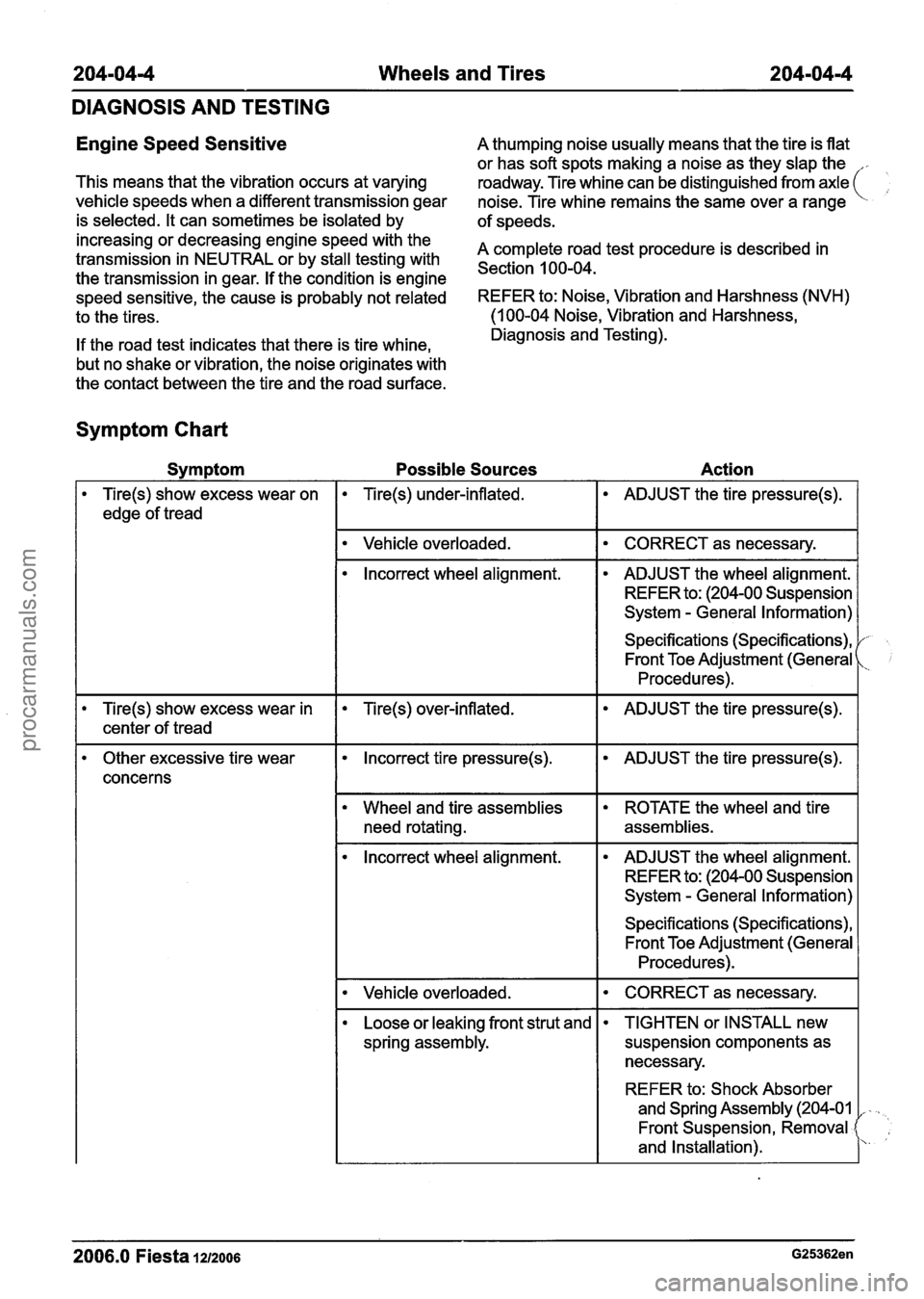
Symptom Chart
Symptom Possible Sources Action
Tire(s) show excess wear on
edge of tread
I Vehicle overloaded. I CORRECT as necessary. I
Tire(s) under-inflated.
lncorrect wheel alignment. ADJUST the tire pressure(s).
ADJUST the wheel alignment.
REFER to: (204-00 Suspension
System
- General Information)
Specifications (Specifications), Front Toe Adjustment (General
Procedures).
Tire(s) show excess wear in Tire(s) over-inflated.
I I
ADJUST the tire pressure(s).
I center of tread
Other excessive tire wear Incorrect tire pressure(s).
concerns
need rotating.
ADJUST the tire pressure(s).
ROTATE the wheel and tire
assemblies.
lncorrect wheel alignment. ADJUST the wheel alignment.
REFER to: (204-00 Suspension
System
- General Information)
Specifications (Specifications), Front Toe Adjustment (General
Procedures).
I Vehicle overloaded.
Loose or leaking front strut and
spring assembly. CORRECT as necessary.
I
2006.0 Fiesta 1212006 G25362en
TIGHTEN
or INSTALL new
suspension components as
necessary.
REFER to: Shock Absorber
and Spring Assembly (204-01
,
Front Suspension, Removal
and Installation).
procarmanuals.com
Page 150 of 1226
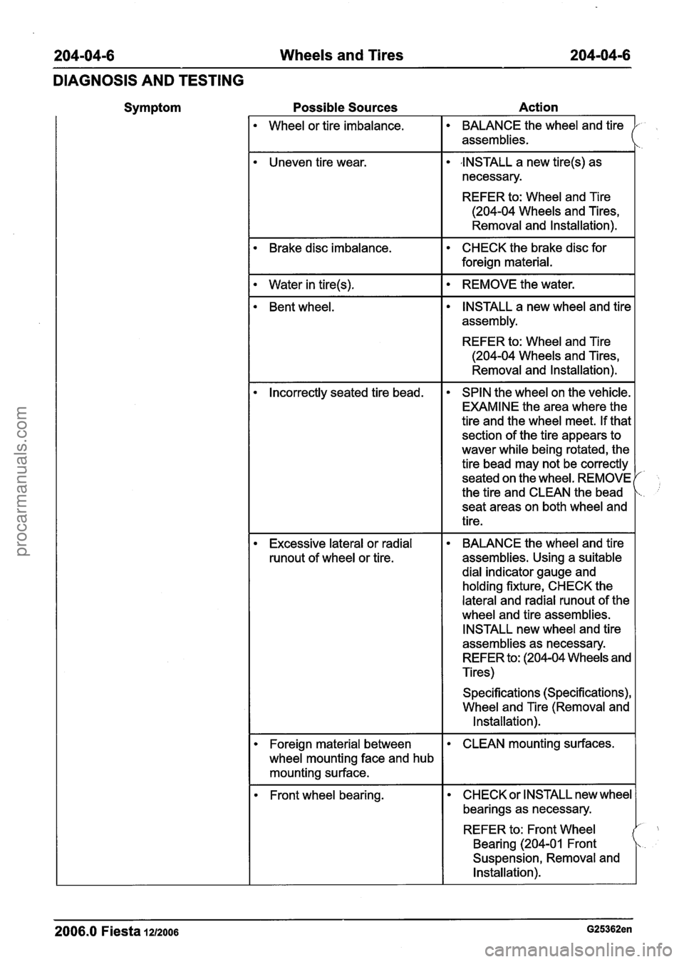
204-04-6 Wheels and Tires 204-04-6
DIAGNOSIS AND TESTING
Symptom Possible
Sources Action
Wheel or tire imbalance. BALANCE the
wheel and tire
assemblies.
Uneven tire wear.
,INSTALL a new tire(s) as
necessary.
REFER to: Wheel and Tire
(204-04 Wheels and Tires,
Removal and Installation).
1. Brake disc imbalance. CHECK
the brake disc for
foreign material.
I . Water in tire(s). I . REMOVE the water. I
Bent wheel. INSTALL
a new wheel and tire
assembly.
REFER to: Wheel and Tire
(204-04 Wheels and Tires,
Removal and Installation).
Incorrectly seated tire bead. SPIN the wheel on the vehicle.
EXAMINE the area where the
tire and the wheel meet. If that
section of the tire appears to
waver while being rotated, the
tire bead may not be correctly
seated on the wheel. REMOVE
the tire and CLEAN the bead
seat areas on both wheel and
tire.
Excessive lateral or radial
runout of wheel or tire. BALANCE the
wheel and tire
assemblies. Using a suitable
dial indicator gauge and
holding fixture, CHECK the
lateral and radial
runout of the
wheel and tire assemblies.
INSTALL new wheel and tire
assemblies as necessary.
REFER to: (204-04 Wheels and
Tires)
Specifications (Specifications),
Wheel and Tire (Removal and
Installation).
Foreign material between
wheel mounting face and hub
mounting surface. CLEAN mounting surfaces.
Front wheel bearing. CHECK
or INSTALL new wheel
bearings as necessary.
REFER to: Front Wheel
Bearing
(204-01 Front
Suspension, Removal and
Installation).
2006.0 Fiesta 12/2006 G25362en
procarmanuals.com
Page 152 of 1226
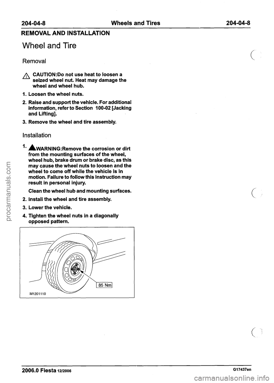
204-04-8 Wheels and Tires 204-04-8
REMOVAL AND INSTALLATION
Wheel and Tire
Removal
A CAUTI0N:Do not use heat to loosen a
seized wheel nut. Heat may damage the
wheel and wheel hub.
I. Loosen the wheel nuts.
2. Raise and support the vehicle. For additional
information, refer to Section
100-02 [Jacking
and Lifting].
3. Remove the wheel and tire assembly.
Installation
AWARNING:R~~~~~ the corrosion or dirt
from the mounting surfaces of the wheel,
wheel hub, brake drum or brake disc, as this
may cause the wheel nuts to loosen and the
wheel to come off while the vehicle is in
motion. Failure to follow this instruction may
result in personal injury.
Clean the wheel hub and mounting surfaces.
2. install the wheel and tire assembly.
3. Lower the vehicle.
4. Tighten the wheel nuts in a diagonally
opposed pattern.
2006.0 Fiesta 1212006 GI 7437en
procarmanuals.com
Page 153 of 1226
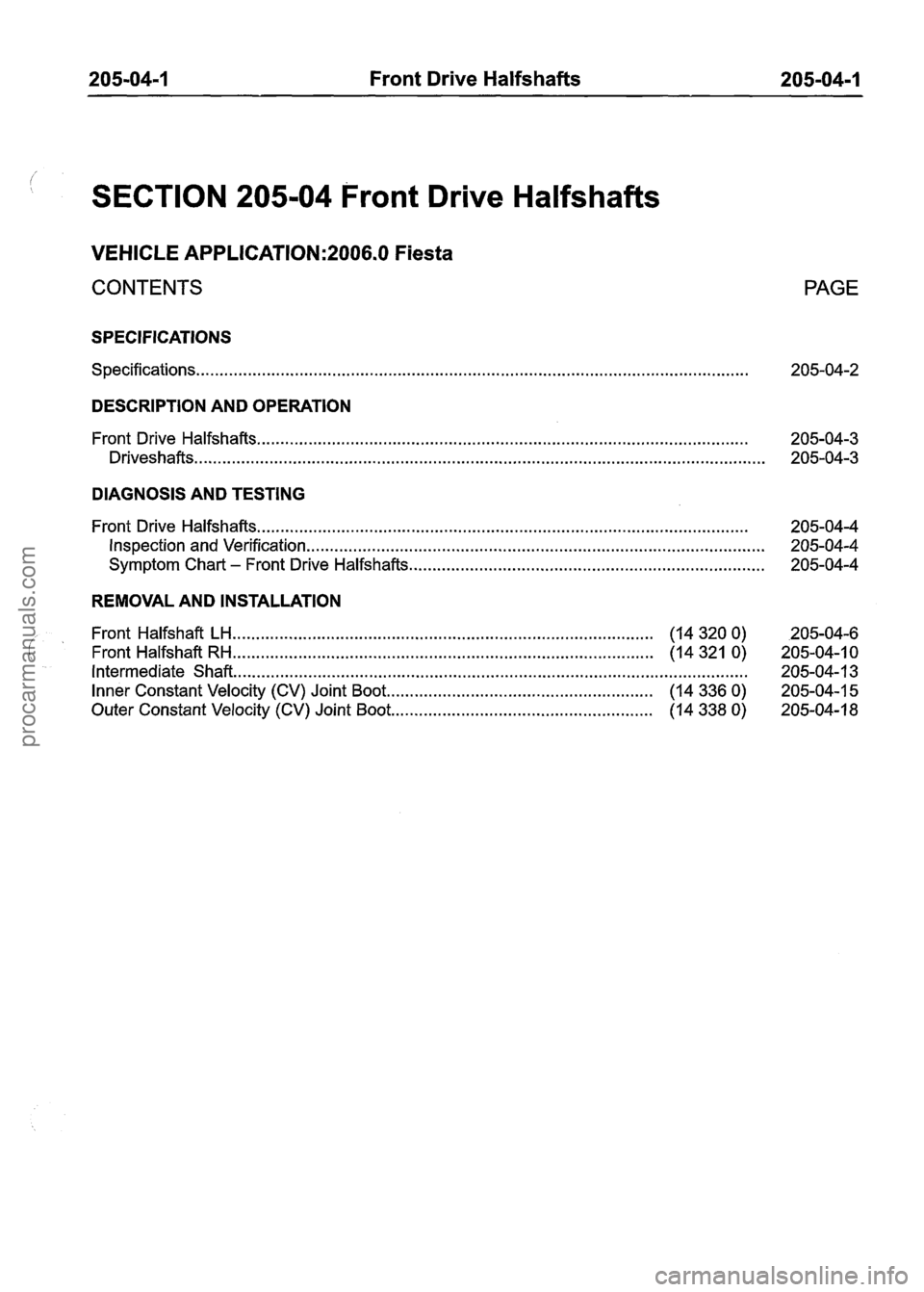
205-04-1 Front Drive Halfshafts 205-04-1
SECTION 205-04 Front Drive Halfshafts
VEHICLE APPLICATION:2006.0 Fiesta
CONTENTS
SPECIFICATIONS
Specifications ........................................................................\
..............................................
PAGE
DESCRIPTION AND OPERATION
........................................................................\
................................. Front Drive Halfshafts 205-04-3
........................................................................\
.................................................. Driveshafts 205-04-3
DIAGNOSIS AND TESTING
........................................................................\
................................. Front Drive Halfshafts 205-04-4
Inspection and Verification ........................................................................\
.......................... 205-04-4
........................................................................\
.... Symptom Chart - Front Drive Halfshafts 205-04-4
REMOVAL AND INSTALLATION
........................................................................\
.................. Front Halfshaft LH (14 320 0) 205-04-6
........................................................................\
.................. Front Halfshaft RH (14 321 0) 205-04-1 0
Intermediate Shaft ........................................................................\
...................................... 205-04-1 3
......................................................... Inner Constant Velocity (CV) Joint Boot (14 336 0) 205-04-1 5
........................................................ Outer Constant Velocity (CV) Joint Boot (14 338 0) 205-04-18
procarmanuals.com
Page 156 of 1226
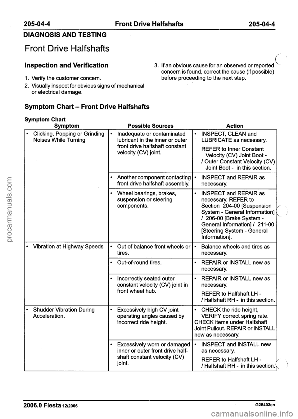
205-0414 Front Drive Halfshafts 205-04-4
DIAGNOSIS AND TESTING
Front Drive Halfshafts
Inspection and Verification 3. If an obvious cause for an observed or reported
concern is found, correct the cause (if possible) c.# '
1. Verify the customer concern. before proceeding
to the next step.
2. Visually inspect for obvious signs of mechanical
or electrical damage.
Symptom Chart - Front Drive Halfshafts
Symptom Chart
Symptom
Possible Sources Action
Clicking, Popping or Grinding
Noises While Turning Inadequate or contaminated INSPECT, CLEAN and
I lubricant in the inner or outer I LUBRICATE as necessary.
I Outer Constant Velocity (CV)
I Joint Boot - in this section.
front drive halfshaft constant
velocity (CV) joint.
REFER to Constant
Velocity (CV) Joint Boot -
Wheel bearings, brakes,
suspension or steering
components.
Another component contacting
front drive halfshaft assembly.
--
INSPECT and REPAIR as
necessary. REFER to
Section 204-00 [Suspension
System
- General Information]
1 206-00 [Brake System -
General Information] I 21 1-00
[Steering System
- General
Information].
INSPECT and REPAIR as
necessary.
- --
Vibration at Highway Speeds
Shudder Vibration During
Acceleration. Out of balance front wheels or
tires. Balance wheels and tires as
necessary.
I Incorrectly seated outer I REPAIR or INSTALL new as I
Out-of-round tires.
constant velocity (CV) joint in necessary.
front wheel hub.
I REFER to Halfshaft LH -
REPAIR or INSTALL new as
necessary.
I I I Halfshaft RH - in this section. I
Excessively high CV joint
operating angles caused by
incorrect ride height. CHECK the ride height,
VERIFY correct spring rate.
CHECK items under Halfshaft
Joint Pullout. REPAIR or INSTALL
new as necessary.
Excessively worn or damaged
I inner or outer front drive half-
- - - - --
2006.0 Fiesta 1212006 G25403en
INSPECT and INSTALL new
as necessary.
shaft constant velocity (CV)
joint. REFER
to Halfshaft LH
-
I Halfshaft RH - in this sectionk 1;
procarmanuals.com