distribution FORD FIESTA 2007 Repair Manual
[x] Cancel search | Manufacturer: FORD, Model Year: 2007, Model line: FIESTA, Model: FORD FIESTA 2007Pages: 1226, PDF Size: 61.26 MB
Page 763 of 1226
Engine Cooling - 1.3L Duratec-8V
(Rocam)ll.25L Duratec-1 6V (Sigma)ll.4L
303-03A-21 Duratec-1 6V (Sigma)/l .6L Duratec-1 6V (Sigma) 303-03A-21
REMOVAL AND INSTALLATION
Water Pump - 1.25L Duratec-1 6V (Sigma)/l.4L Duratec-1 6V
(Sigma)/l .6L Duratec-1 6V (Sigma)(24 404 0)
Removal
Vehicles built up to 0412005
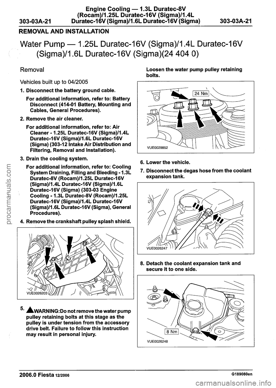
Loosen the water pump pulley retaining
bolts.
1. Disconnect the battery ground cable.
For additional information, refer to: Battery
Disconnect
(414-01 Battery, Mounting and
Cables, General Procedures).
2. Remove the air
cleaner.
For additional information, refer to: Air
Cleaner - 1.25L Duratec-1 6V (Sigma)ll.4L
Duratec-1 6V (Sigma)ll .6L Duratec-1 6V
(Sigma) (303-12 Intake Air Distribution and
Filtering, Removal and Installation).
3. Drain the cooling system.
6. Lower the vehicle. For additional information, refer to: Cooling
System Draining, Filling and Bleeding - 1.3~ 7. Disconnect the degas hose from the coolant
Duratec-8V (Rocam)ll.25L Duratec-1 6V expansion tank.
(Sigma)ll.4L Duratec-1 6V (Sigma)ll .6L
Duratec-1 6V (Sigma) (303-03 Engine
Cooling - 1.3L DuratecdV (Rocam)ll.25L
Duratec-1 6V (Sigma)ll.4L Duratec-1 6V
(Sigma)ll .6L Duratec-1 6V (Sigma), General
Procedures).
4. Remove the crankshaft
pulley splash shield.
5m AWARNING:D~ not remove the water pump
pulley retaining bolts at this stage as the
pulley is under tension from the accessory
drive
belt. Failure to follow this instruction
may
result in personal injury. 8.
Detach the
coolant expansion tank and
secure
it to one side.
2006.0 Fiesta 1212006 GI 89080en
procarmanuals.com
Page 794 of 1226
303-03B-24 Engine Cooling - 2.OL Duratec-HE (M14) 303-03B-24
REMOVAL AND INSTALLATION
Coolant Outlet Connector
Removal
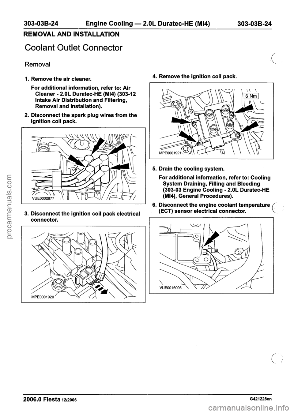
1. Remove the air cleaner.
For additional information, refer to: Air
Cleaner
- 2.OL Duratec-HE (M14) (303-12
Intake Air Distribution and Filtering,
Removal and Installation).
2. Disconnect the spark plug wires from the
ignition coil pack.
4. Remove the ignition coil pack.
5. Drain the cooling system.
For additional information, refer to: Cooling
System Draining, Filling and Bleeding
(303-03 Engine Cooling
- 2.OL Duratec-HE
(M14), General Procedures).
6. Disconnect the engine coolant temperature
3. Disconnect the ignition coil pack electrical
(ECT) sensor electrical connector.
connector.
2006.0 Fiesta 1212006 G421228en
procarmanuals.com
Page 803 of 1226
Fuel Charging and Controls - 1.25L
Duratec-1 6V (Sigma)llI4L Duratec-1 6V
(Sigma)llI6L Duratec-1 6V (Sigma)
REMOVAL AND INSTALLATION
Fuel Charging Wiring Harness(36 437 0)
Removal
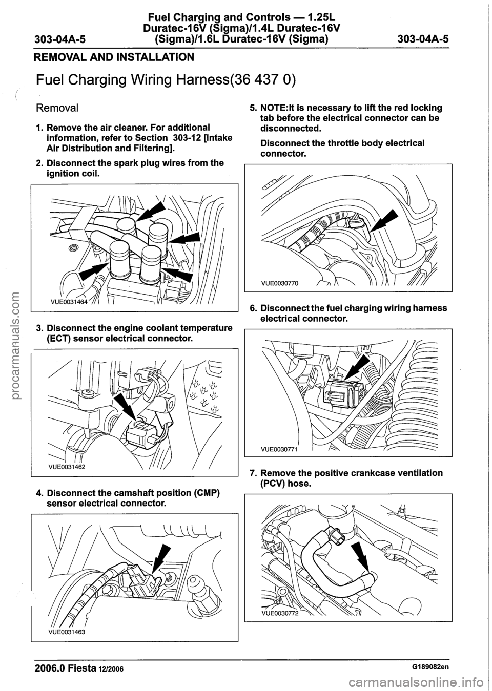
1. Remove the air cleaner. For additional
5. N0TE:lt is necessary to lift the red locking
tab before the electrical connector can be
disconnected.
information, refer to Section
303-12 [Intake the throttle body electrical Air Distribution and Filtering].
connector.
2. Disconnect the spark plug wires from the
ignition coil.
6. Disconnect the fuel charging wiring harness
electrical connector.
3. Disconnect the engine coolant temperature
(ECT) sensor electrical connector.
(
7. Remove the positive crankcase ventilation
(PCV) hose.
4. Disconnect the camshaft position (CMP)
sensor electrical connector.
2006.0 Fiesta 1212006 GI 89082en
procarmanuals.com
Page 805 of 1226
Fuel Charging and Controls - 1.25L
Duratec-1 6V (Sigma)llI4L Duratec-1 6V
303-04A-7 (Sigma)llI6L Duratec-1 6V (Sigma) 303-04A-7
REMOVAL AND INSTALLATION
Fuel Injection Supply Manifold(23 450 0)
Removal
WARNINGS:
A Do not smoke or carry lighted tobacco or
open flame of any type when working on
or near any fuel related components.
Highly flammable vapors are always
present and can ignite. Failure to follow
these instructions may result in personal
injury.
A This procedure involves fuel handling. Be
prepared for fuel spillage at all times and
always observe fuel handling precautions.
Failure to follow these instructions may
result in personal injury.
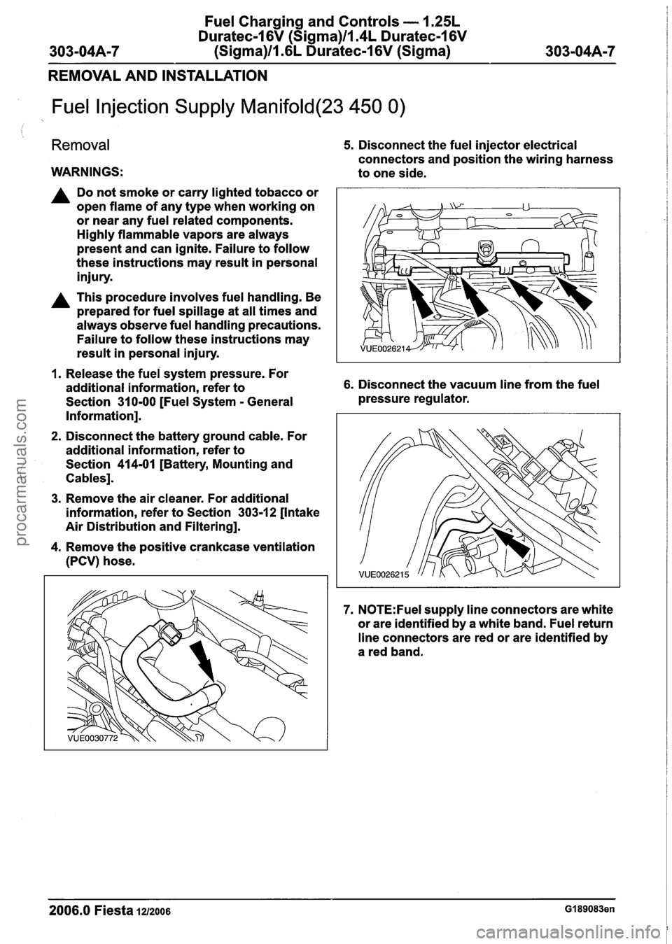
5. Disconnect the fuel injector electrical
connectors and position the wiring harness
to one side.
1. Release the fuei system pressure. For
additional information, refer to 6. Disconnect the vacuum line from the fuel
Section
31 0-00 [Fuel System - General pressure
regulator.
Information].
2. Disconnect the battery ground cable. For
additional information, refer to
Section
414-01 [Battery, Mounting and
Cables].
3. Remove the air cleaner. For additional
information, refer to Section
303-12 [Intake
Air Distribution and Filtering].
4. Remove the positive crankcase ventilation
(PCV) hose.
7. N0TE:Fuel supply line connectors are white
or are identified by a white band. Fuel return
line connectors are red or are identified by
a red band.
2006.0 Fiesta 1212006 GI 89083en
procarmanuals.com
Page 835 of 1226
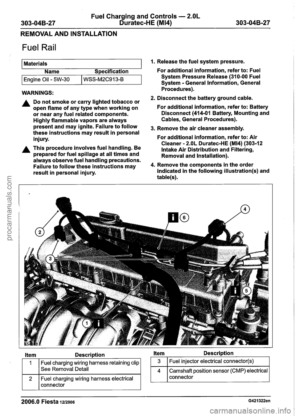
Fuel Charging and Controls - 2.OL
303-04B-27 Duratec-HE (M14) 303-04B-27
REMOVAL AND INSTALLATION
Fuel Rail
Materials Name Specification
I Engine Oil - 5W-30 I WSS-~2~91 3-B I
WARNINGS:
A Do not smoke or carry lighted tobacco or
open flame of any type when working on
or near any fuel related components.
Highly flammable vapors are always
present and may ignite. Failure to follow
these instructions may result in personal
injury.
A This procedure involves fuel handling. Be
prepared for fuel spillage at all times and
always observe fuel handling precautions.
Failure to follow these instructions may
result in personal injury.
1. Release the fuel system pressure.
For additional information, refer to: Fuel
System Pressure Release (31 0-00 Fuel
System
- General Information, General
Procedures).
2. Disconnect the battery ground cable.
For additional information, refer to: Battery
Disconnect
(414-01 Battery, Mounting and
Cables, General Procedures).
3. Remove the air cleaner assembly.
For additional information, refer to: Air
Cleaner
- 2.OL Duratec-HE (M14) (303-1 2
intake Air Distribution and Filtering,
Removal and Installation).
4. Remove the components in the order
indicated in the following
illustration(s) and
table(s).
Item Description Item Description
Fuel charging wiring harness retaining clip
See Removal Detail
Fuel charging wiring harness electrical
connector
2006.0 Fiesta 1212006 G421322en
procarmanuals.com
Page 893 of 1226

Engine Emission Control - 1.3L Duratec-8V
(Rocam)llI25L Duratec-1 6V (Sigma)llm4L
303-O8A-7 Duratec-1 6V (Sigma)ll .6L Duratec-1 6V (Sigma) 303-0844-7
REMOVAL AND INSTALLATION
Crankcase Vent Oil Separator
i
Removal
1. Remove the air cleaner. For additional
information, refer to Section
303-1 2 [Intake
Air Distribution and Filtering].
2. Remove the intake manifold. For additional
information, refer to Section 303-01A
[Engine
-- 1.25L Duratec-1 6V (Sigma)ll.4L
Duratec-1 6V (Sigma)llm6L Duratec-1 6V
(Sigma)] I 303-01 B [Engine -- 1.4L
Duratorq-TDCi (DV) Diesel] I 303-01 C [Engine
-- 1.3L Duratec-8V (Rocam)] I 303-01 D
[Engine
-- 2.OL Duratec-HE (M14)I 1 303-01 E
[Engine
-- 1.6L Duratorq-TDCi (DV) Diesel].
3. Remove the crankcase vent oil separater.
Discard the gasket.
Installation
I. N0TE:lnstall a new crankcase vent oil
separator gasket.
To install, reverse the removal procedure.
2006.0 Fiesta 1212006 G210048en
procarmanuals.com
Page 905 of 1226

303-1 2-1 Intake Air Distribution and Filtering 303-1 2-1
SECTION 303-12 lntake Air Distribution and Filtering
VEHICLE APPLICATION:2006.0 Fiesta
CONTENTS
SPECIFICATIONS
Specifications..
. . . . . .. . .. . .. .. . . .. . . . . ....... . . . .. . . . . .. .. . . . . .. . . . . . . .. .. . . . . .. .. . . .. .... ...... .. .. .. . . . . .. . . ........ .. .. .. .. . . . . .
DESCRIPTION AND OPERATION
lntake Air Distribution and Filtering - 1.4L Duratec-1 6V (Sigma)/l .6L Duratec-1 6V
(Sigma) ........................................................................\
.....................................................
lntake manifold ........................................................................\
...........................................
lntake Air Distribution and Filtering - 2.OL Duratec-HE (M14) ...........................................
2.OL Duratec HE (M14) engine ........................................................................\
....................
DIAGNOSIS AND TESTING
lntake Air Distribution and Filtering.. . . . . . . . . . . . . . . . . . . . . . . . . . . . . . . . . . . . . . . . . . . . . . . . . . . . . . . . . . . . . . . . . . . . . . . . . . . . . . . . . . . .
Inspection and Verification ........................................................................\
..........................
Symptom Chart.. . . . . . . . . . . . . . . . . . . . . . . . . . . . . . . . . . . . . . . . . . . . . . . . . . . . . . . . . . . . . . . . . . . . . . . . . . . . . . . . . . . . . . . . . . . . . . . . . . . . . . . . . . . . . . . . . .
!. ' REMOVAL AND INSTALLATION
Air
Cleaner - 1.25L Duratec-1 6V (Sigma)/l.4L Duratec-I 6V (Sigma)/l .6L
Duratec-1
6V (Sigma) ........................................................................\
............ (23 174 0)
Air
Cleaner - 2.OL Duratec-HE (M14) ..................... .......................... .......... .................... ...
PAGE
procarmanuals.com
Page 906 of 1226

303-1 2-2 Intake Air Distribution and Filtering 303-1 2-2
SPECIFICATIONS
Toraue S~ecifications
1 1.4L Duratorq-TDCi (DV) diesel engine I I I I
Description
Air cleaner intake pipe retaining bolt
- vehicles with
Air cleaner retaining screws
- vehicles with 1.4L
Duratorq-TDCi (DV) diesel engine
Air cleaner outlet hose retaining clip
- vehicles with
1.6L Duratorq-TDCi (DV) diesel engine
Nm
4
Air cleaner intake pipe duct retaining bolts - vehicles
with
I .6L Duratorq-TDCi (DV) diesel engine
Charge air cooler hose retaining clamps
- 1.6L
Duratorq-TDCi (DV) diesel engine
I b-ft
-
Charge air cooler retaining bolts - 1.6L Duratorq-
TDCi (DV) diesel engine
I b-in
35
Radiator support bracket retaining bolts - 1.6L
Duratorq-TDCi (DV) diesel engine
2006.0 Fiesta 1212006 G148224en
procarmanuals.com
Page 907 of 1226

303-1 2-3 Intake Air Distribution and Filtering 303-1 2-3
DESCRIPTION AND OPERATION
lntake Air Distribution and Filtering - 1.4L Duratec-I 6V
I (Sigma)/l .6L Duratec-1 6V (Sigma)
lntake manifold
The 1.41 and 1.61 versions feature a revised intake
manifold. The overall length of the intake pipes has
been increased, but the pipes are of equal length
on all cylinders. This has resulted in increased
torque in the lower engine speed range and a
reduction in noise levels.
I 1 I Mounting for the throttle valve unit I
FIT-MAP sensor I
The mounting for the electronic throttle valve is
located inside the intake manifold between the
intake pipes of cylinders 1 and 2. The T-MAP
sensor, which is used on both the 1.41 and 1.61
versions, is situated next to the throttle valve unit.
2006.0 Fiesta 1212006 GI 79057en
procarmanuals.com
Page 908 of 1226

303-1 2-4 Intake Air Distribution and Filtering 303-1 2-4
DESCRIPTION AND OPERATION
lntake Air Distribution and Filtering - 2.OL Duratec-HE (M14)
(
2.OL Duratec HE (M14) engine
lntake manifold and ancillary components
Item Descri~tion
I 1 I Intake manifold I
1 2 1 lntake manifold tuning valve solenoid I
1 3 ( lntake manifold tuning valve I
141
lntake manifold tuning valve solenoid to
intake manifold vacuum pipe
Item Description
151
lntake manifold tuning valve solenoid to
intake manifold tuning valve vacuum pipe
1 6 1 lntake manifold tuning valve actuator I
1 7 1 Intake manifold tuning valve flaps I
2006.0 Fiesta 1212006 G421936en
procarmanuals.com