Tank FORD FIESTA 2007 Repair Manual
[x] Cancel search | Manufacturer: FORD, Model Year: 2007, Model line: FIESTA, Model: FORD FIESTA 2007Pages: 1226, PDF Size: 61.26 MB
Page 943 of 1226
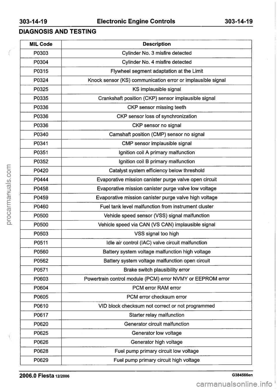
Electronic Engine Controls
DIAGNOSIS AND TESTING
I PO304 I Cylinder No. 4 misfire detected I
/ I
KS implausible signal I
MIL Code
PO303
PO31 5
PO324
1 PO335 1 Crankshaft position (CKP) sensor implausible signal I
Description
Cylinder No. 3 misfire detected
Flywheel segment adaptation at the Limit
Knock sensor (KS) communication error or implausible signal
1 PO336 1 CKP sensor missing teeth I
1 PO336 1 CKP sensor loss of synchronization I
1 PO336 1 CKP sensor no signal I
I PO340 I Camshaft position (CMP) sensor no signal I
I PO341 I CMP sensor implausible signal I
I PO351 I Ignition coil A primary malfunction I
1 PO352 1 Ignition coil B primary malfunction I
I PO420 I Catalyst system efficiency below threshold I
1 PO444 1 Evaporative mission canister purge valve open circuit I
1 PO458 1 Evaporative mission canister purge valve low voltage I
I '1 PO459 1 Evaporative mission canister purge valve high voltage I
I PO460 I Fuel tank level malfunction from instrument cluster I
-3 I VSS signal too high I
PO500
PO500
Vehicle speed sensor (VSS) signal malfunction
Vehicle speed via CAN (VS CAN) implausible signal
PO51 1
PO560
I PO603 I Powertrain control module (PCM) error NVMY or EEPROM error 1
Idle air control (IAC) valve circuit malfunction
Battery system voltage malfunction high voltage
PO562
PO571
I PO604 I PCM error RAM error I
Battery system voltage malfunction open circuit
Brake switch plausibility error
PO605 I PCM error checksum error I
I PO610 I VID block checksum not correct or not programmed I
I PO617 I Starter relay malfunction I
I PO620 I Generator circuit malfunction I
1 PO628 1 Fuel pump primary circuit low voltage I
I
7 1 Fuel pump primary circuit high voltage I
2006.0 Fiesta 1212006 G384566en
PO625
PO626
Generator low voltage
Generator high voltage
procarmanuals.com
Page 1117 of 1226
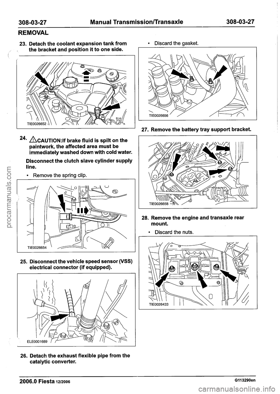
308-03-27 Manual TransmissionlTransaxle 308-03-27
REMOVAL
23. Detach the coolant expansion tank from Discard the gasket.
, . the bracket and position it to one side.
24m ACAUTION:~~ brake fluid is spilt on the
paintwork, the affected area must be
immediately washed down with cold water.
Disconnect the clutch slave cylinder supply
line.
Remove the spring clip.
25. Disconnect the vehicle speed sensor (VSS)
electrical connector (if equipped).
26. Detach the exhaust flexible pipe from the
catalytic converter.
27. Remove the battery tray support bracket.
28. Remove the engine and transaxle rear
mount.
Discard the nuts.
2006.0 Fiesta 1212006 GI1 3290en
procarmanuals.com
Page 1154 of 1226
308-03-64 Manual Transmission/Transaxle 308-03-64
INSTALLATION
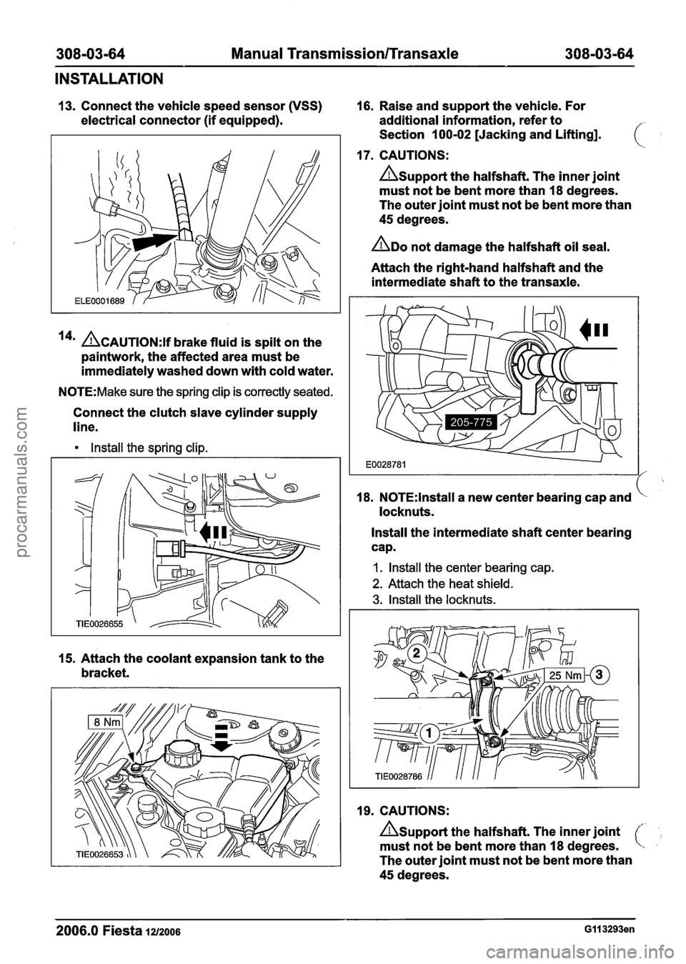
13. Connect the vehicle speed sensor (VSS) 16. Raise and support the vehicle. For
electrical connector (if equipped). additional information, refer to
Section 100-02 [Jacking and Lifting].
17. CAUTIONS:
Asupport the halfshaft. The inner joint
must not be bent more than 18 degrees.
The outer joint must not be bent more than
45 degrees.
ADO not damage the halfshaft oil seal.
Attach the right-hand halfshaft and the
intermediate shaft to the transaxle.
14' ACAUTION:~~ brake fluid is spilt on the
paintwork, the affected area must be
immediately washed down with cold water.
N0TE:Make sure the spring clip is correctly seated.
Connect the clutch slave cylinder supply
line.
Install the spring clip.
15. Attach the coolant expansion tank to the
bracket. 18.
N0TE:lnstall a
new center bearing cap and
locknuts.
Install the intermediate shaft center bearing
cap.
I. Install the center bearing cap.
2. Attach the heat shield.
3. Install the locknuts.
19. CAUTIONS:
Asupport the halfshaft. The inner joint
must not be bent more than 18 degrees.
The outer joint must not be bent more than
45 degrees.
2006.0 Fiesta 1212006 GI I 3293en
procarmanuals.com
Page 1187 of 1226
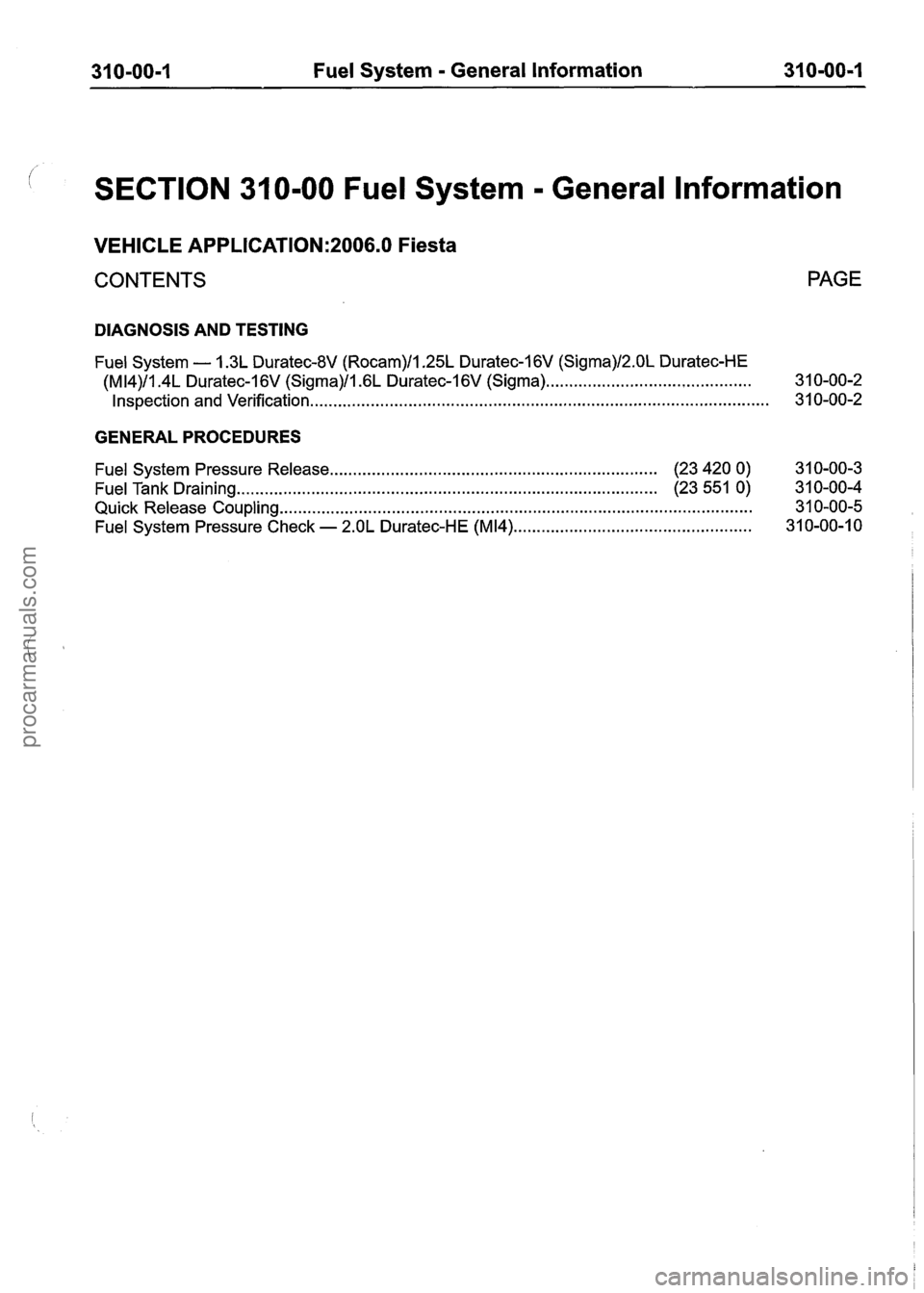
31 0-00-1 Fuel System - General Information 31 0-OO=l
SECTION 31 0-00 Fuel System - General lnformation
VEHICLE APPLICATION:2006.0 Fiesta
CONTENTS PAGE
DIAGNOSIS AND TESTING
Fuel System - 1.3L Duratec-8V (Rocam)ll.25L Duratec-I 6V (Sigma)/2.0L Duratec-HE
(M14)/1.4L Duratec-1 6V (Sigma)/l .6L
Duratec-1 6V (Sigma) ............................................ 3 1 0-00-2
........................................................................\
......................... Inspection and Verification. 3 1
0-00-2
GENERAL PROCEDURES
Fuel System Pressure Release .................................................................... (23 420 0) 3 1 0-00-3
Fuel Tank Draining
........................................................................\
.................. (23 551 0) 3 1 0-00-4
Quick Release Coupling
........................................................................\
............................. 3 1 0-00-5
................................................... Fuel System Pressure Check - 2.OL Duratec-HE (M14) 31 0-00-1 0
procarmanuals.com
Page 1188 of 1226
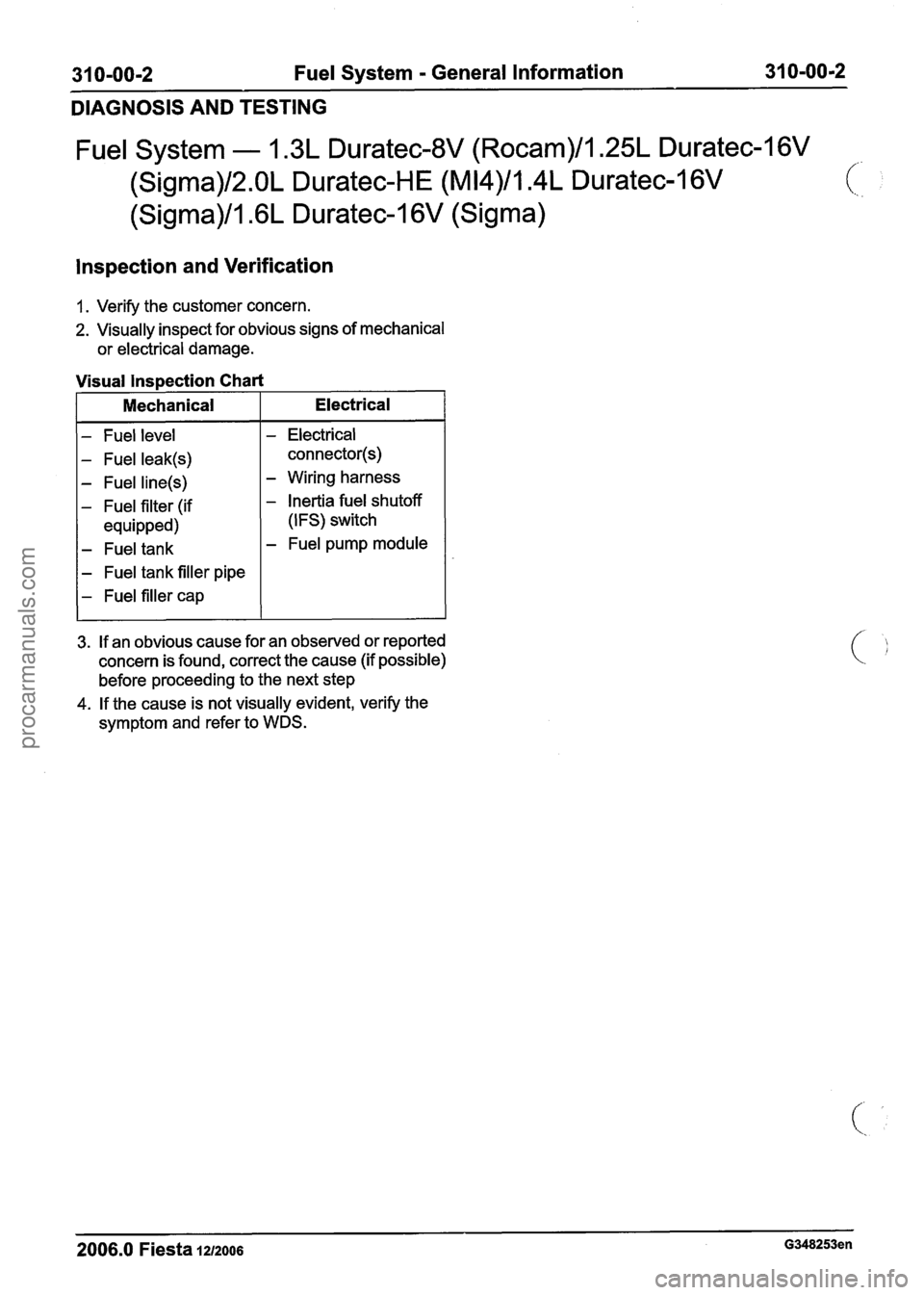
31 0-00-2 Fuel System - General Information 31 0-00-2
DIAGNOSIS AND TESTING
Fuel System - 1.3L Duratec-8V (Rocam)/l.25L Duratec-1 6V
(Sigma)/2.0L Duratec-HE (M14)/1.4L Duratec-I 6V
(Sigma)/l.GL Duratec-1 6V (Sigma)
lnspection and Verification
1. Verify the customer concern.
2. Visually inspect for obvious signs of mechanical
or electrical damage.
- Fuel level
- Fuel leak(s)
- Fuel line(s)
- Fuel filter (if
equipped)
- Fuel tank
- Fuel tank filler pipe
- Fuel filler cap
Visual lnspection Chart
- Electrical
connector(s)
- Wiring harness
- Inertia fuel shutoff
(IFS) switch
- Fuel pump module
I Mechanical
3. If an obvious cause for an observed or reported
concern is found, correct the cause (if possible)
before proceeding to the next step
4. If the cause is not visually evident, verify the
symptom and refer to WDS.
Electrical
-
2006.0 Fiesta 1212006 G348253en
procarmanuals.com
Page 1190 of 1226
31 0-00-4 Fuel System - General Information 31 0-00-4
GENERAL PROCEDURES
Fuel Tank Draining(23 551 0)
General Eaui~ment
I Fuel tank draining equipment I
Draining
WARNINGS:
A Do not smoke or carry lighted tobacco or
open flame of any type when working on
or near any fuel related components.
Highly flammable vapors are always
present and may ignite. Failure to follow
these instructions may result in personal
injury.
A The fuel system remains pressurized for a
long time after the ignition is switched off.
The fuel pressure must be relieved before
attempting any repairs. Failure to follow
these instructions may result in personal
injury.
I. Disconnect the battery ground cable. For
additional information, refer to
Section
414-01 [Battery, Mounting and
Cables].
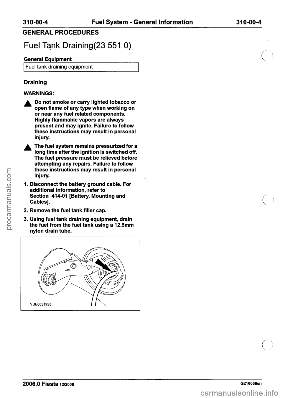
2. Remove the fuel tank filler cap.
3. Using fuel tank draining equipment, drain
the fuel from the fuel tank using a
12.5mm
nylon drain tube.
2006.0 Fiesta 1212006 G210056en
procarmanuals.com
Page 1192 of 1226
31 0-00-6 Fuel System - General Information 31 0-00-6
GENERAL PROCEDURES
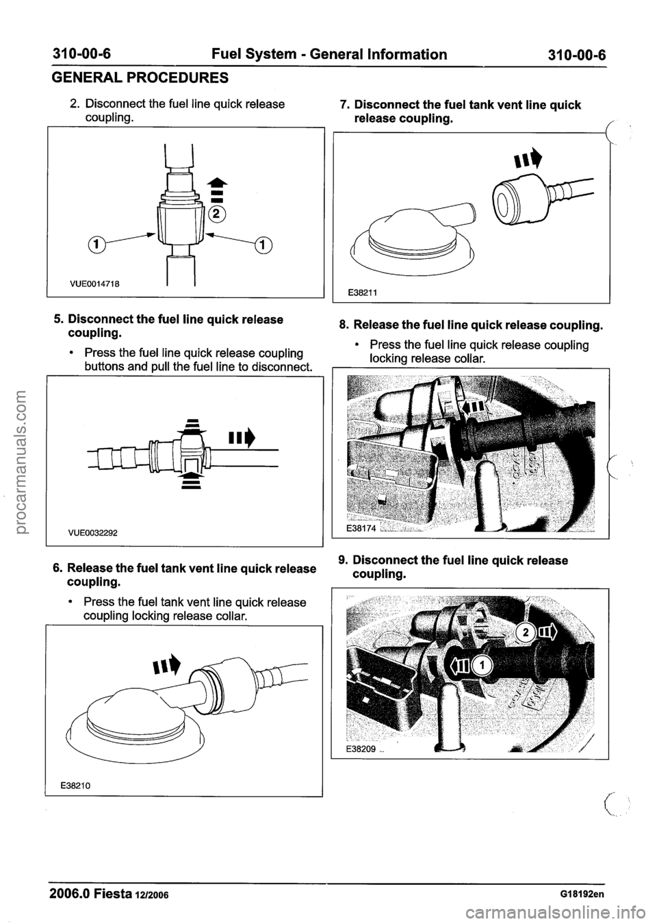
5. Disconnect the fuel line quick release
coupling.
2. Disconnect the fuel line quick release 7. Disconnect the fuel tank vent line quick
coupling. release coupling.
8. Release the fuel line quick release coupling.
-
4 =
b
.-
VUE0014718
- - Press the fuel line quick release coupling
Press the fuel line quick release coupling
locking release collar.
buttons and pull the fuel line to disconnect.
63
E38211
9. Disconnect the fuel line quick release 6. Release the fuel tank vent line quick release
coupling.
Press the fuel tank vent line quick release
coupling locking release collar.
2006.0 Fiesta 1212006 GI 81 92en
procarmanuals.com
Page 1194 of 1226
31 0-00-8 Fuel System - General Information 31 0-00-8
GENERAL PROCEDURES
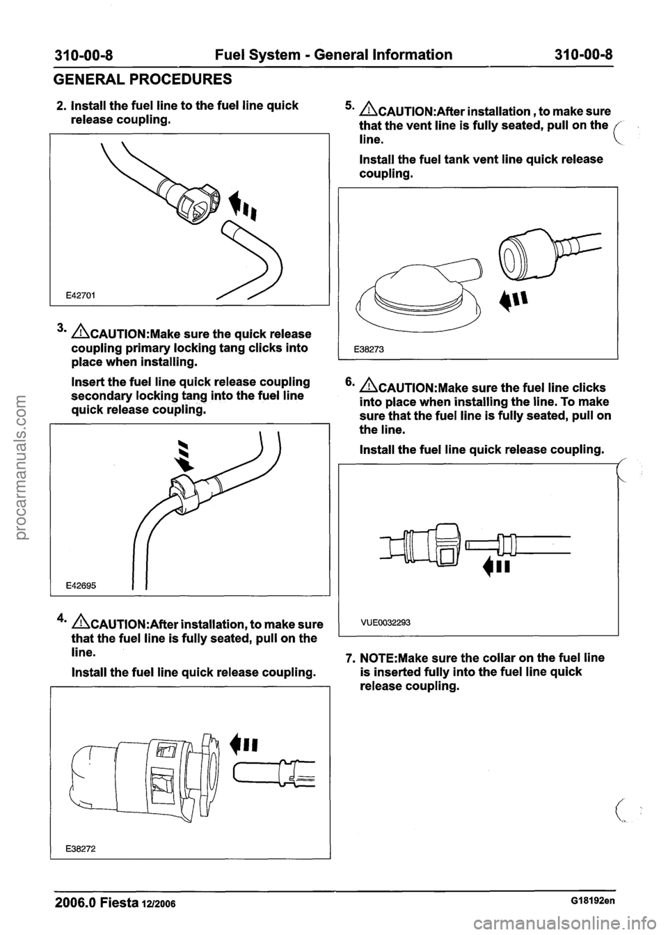
2. Install the fuel line to the fuel line quick
release coupling. 5m &AUTION:A~~~~ installation , to make sure
that the vent line is fully seated, pull on the
line.
3m &AUTION:M~~~ sure the quick release
coupling primary locking tang clicks into
place when installing. Install the fuel
tank vent line quick release
coupling.
Insert the fuel line quick release coupling
secondary locking tang into the fuel line
&AUTION:M~~~ sure the fuel line clicks
into place when installing the line. To make
quick release coupling.
sure that the fuel line is fully seated, pull on
the line.
4m &AUTION:A~~~~ installation, to make sure
that the fuel line is fully seated, pull on the Install the
fuel line quick release coupling.
/'
line. 7. N0TE:Make sure the collar on the fuel line
Install the fuel line quick release coupling. is
inserted fully into the fuel line quick
release coupling.
2006.0 Fiesta 1212006 GI 81 92en
procarmanuals.com
Page 1199 of 1226
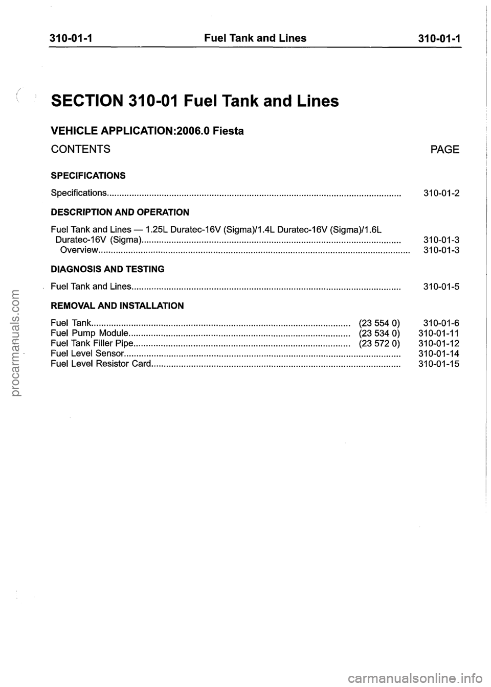
31 0-01 -1 Fuel Tank and Lines 31 0-01 -1
1 SECTION 31 0-01 Fuel Tank and Lines
VEHICLE APPLICATION:2006.0 Fiesta
CONTENTS
SPECIFICATIONS
Specifications.. . . . . . . . . . . . . . . . . . . . . . . . . . . . . . . . . . . . . . . . . . . . . . . . . . . . . . . . . . . . . . . . . . . . . . . . . . . . . . . . . . . . . . . . . . . . . . . . . . . . . . . . . . . . . . . . . . . . .
PAGE
DESCRIPTION AND OPERATION
Fuel Tank and Lines - 1.25L Duratec-I 6V (Sigma)/l.4L Duratec-1 6V (Sigma)/l .6L
Duratec-I 6V (Sigma) ...... . . .. .. .... .. .... . . .... . . . . .... ...... .. .. . . . . ...... . . . . ........ .. .. .. .. . . . . . . . ... .. . . . . . . . . . . .. .... 31 0-01 -3
Overview..
. . . . . . . . . . . . . . . . . . . . . . . . . . . . . . . . . . . . . . . . . . . . . . . . . . . . . . . . . . . . . . . . . . . . . . . . . . . . . . . . . . . . . . . . . . . . . . . . . . . . . . . . . . . . . . . . . . . . . . . . . . . 3 1 0-0 1 -3
DIAGNOSIS AND TESTING
. Fuel Tank and Lines ........................................................................\
....................................
REMOVAL AND INSTALLATION
Fuel Tank ..... . . ...... . . . ... . . ...... .... .. . . . . . . . . . . . . . . . . . . . . . . . . . ...... . . . . . . . . . . . . . . . . . . . (23 554 0)
31 0-01 -6
Fuel Pump Module. ........................................................................\
........ . (23 534 0)
31 0-01 -1 1
Fuel Tank Filler Pipe ........................................................................\
............... (23 572 0) 31 0-01-12
Fuel Level Sensor ..... . . . . . . . . . .. .... .. .. .... .. .. . . .. .. .. . . . . . . . . . . . . .. ...... .. . . .. .... . . .. . . . . .. . . .. .... . ... .. .. .. . . .. . . . . . . .. . 31 0-01 -1 4
Fuel Level Resistor Card ..... . . . . .. .. . . .. . . . . .. . . . . .. ...... . . . . . . . ..... . . . ..... . . . . . . . . . . . . . . . . . . . . . . 31 0-01 -1 5
procarmanuals.com
Page 1200 of 1226
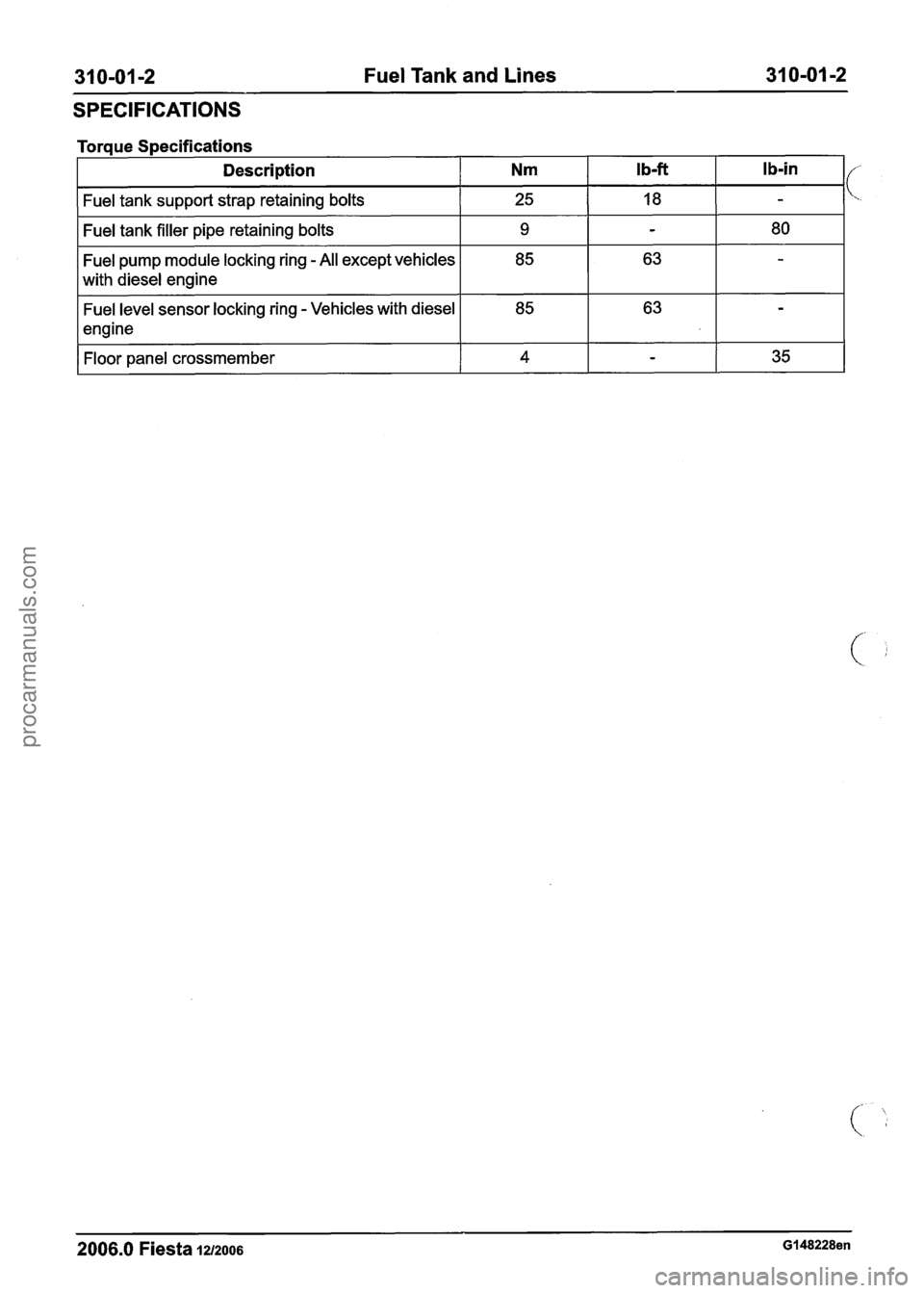
31 0-01 -2 Fuel Tank and Lines 31 0-01 -2
SPECIFICATIONS
Torque Specifications
Description
Nm Ib-ft I b-in I/
Fuel tank support strap retaining bolts I 25 I 18 I -
Fuel tank filler pipe retaining bolts I 9 I - I 80 I
Fuel pump module locking ring - All except vehicles
with diesel engine
Fuel level sensor locking ring
- Vehicles with diesel
engine
Floor panel crossmember
I 4 I - I 35 I
2006.0 Fiesta 1212006 GI 48228en
procarmanuals.com