automatic transmission fluid FORD FIESTA 2007 Workshop Manual
[x] Cancel search | Manufacturer: FORD, Model Year: 2007, Model line: FIESTA, Model: FORD FIESTA 2007Pages: 1226, PDF Size: 61.26 MB
Page 71 of 1226
100-04-15 Noise, Vibration and Harshness 100-04-15
DIAGNOSIS AND TESTING
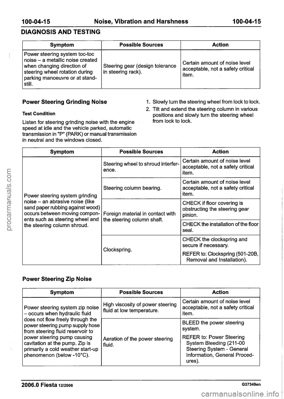
Power Steering Grinding Noise 1. Slowly turn the steering wheel from lock to lock.
Test Condition
Action
Certain amount of noise level
acceptable, not a safety critical
item.
Symptom
Power steering system toc-toc
noise - a metallic noise created
when changing direction of
steering wheel rotation during
parking manoeuvre or at stand-
still.
2. Tilt and extend the steering column in various
positions and slowly turn the steering wheel
Possible Sources
gear (design tolerance
in steering rack).
Listen for steering grinding noise with the engine from lock to lock.
speed at idle and the vehicle parked, automatic
transmission in "P" (PARK) or manual transmission
in neutral and the windows closed.
Power Steering Zip Noise
Symptom Possible Sources Action
Power steering system grinding
noise
- an abrasive noise (like
sand paper rubbing against wood)
occurs between moving compon-
ents such as steering wheel and
the steering column shroud.
2006.0 Fiesta 1212006 G37349en
Steering wheel to shroud interfer-
ence.
Steering column bearing.
Foreign material in contact with
the steering column
shaft.
Clockspring.
Action
Certain amount of noise level
acceptable, not a safety critical item.
BLEED the power steering
system.
REFER
to: Power Steering
System Bleeding
(21 1-00
Steering System
- General
Information, General Proced-
ures).
Symptom
Power steering system zip noise
- occurs when hydraulic fluid
does not flow freely through the
power steering pump supply hose
from steering fluid reservoir to
power steering
pump causing
cavitation
at the pump. Zip is
primarily a cold weather start-up
phenomenon (below -1 0°C). Certain amount
of noise level
acceptable, not a safety critical
item.
Certain amount of noise level
acceptable, not a safety critical
item.
CHECK if floor covering is
obstructing the steering gear
pinion.
CHECK the installation of the floor
seal.
CHECK the clockspring and
secure if necessary.
REFER to: Clockspring (501
-208,
Removal and Installation).
Possible Sources
steering
Aeration of the power steering
fluid.
procarmanuals.com
Page 158 of 1226
205-04-6 Front Drive Halfshafts 205-04-6
REMOVAL AND INSTALLATION
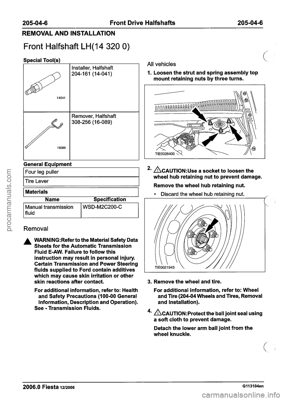
Front Halfshaft LH(14 320 0)
I I Installer, Halfshaft
(%. .
1 All vehicles
1. Loosen the strut and spring assembly top
mount retaining nuts by three turns.
General
Eaui~ment
I Four leg puller I
Tire Lever
Materials
Name Specification
Removal
Manual transmission
1 fluid
A WARNING:Refer to the Material Safety Data
Sheets for the Automatic Transmission
Fluid
E-AW. Failure to follow this
instruction may result in personal injury.
Certain Transmission and Power Steering
fluids supplied to Ford contain additives
which may cause skin irritation or other
skin reactions after contact.
WSD-M2C200-C
2' ACAUTION:~~~ a socket to loosen the
wheel hub retaining nut to prevent damage.
Remove the wheel hub retaining nut.
Discard the wheel hub retaining nut. ,'
3. Remove the wheel and tire.
For additional information, refer to: Health For
additional information, refer to: Wheel
and Safety Precautions
(1 00-00 General and
Tire (204-04 Wheels and Tires, Removal
Information, Description and Operation). and
Installation).
See
- Transmission Fluids.
4m Ac~u~10~:~rotect the ball joint seal using
a soft cloth to prevent damage.
Detach the lower arm ball joint from the
wheel knuckle.
2006.0 Fiesta IZIZOO~ G113104en
procarmanuals.com
Page 159 of 1226
205-04-7 Front Drive Halfshafts 205-04-7
REMOVAL AND INSTALLATION
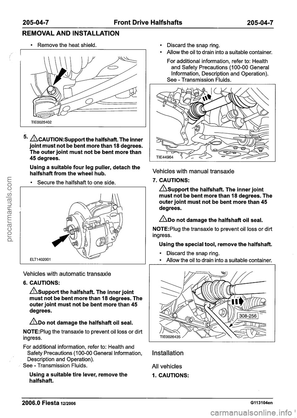
Remove the heat shield.
5m ~~~~~~~~~~~~~~~t the halfshaft. The inner
joint must not be bent more than
18 degrees.
The outer joint must not be bent more than
45 degrees.
Using a suitable four leg puller, detach the
halfshaft from the wheel hub.
Secure the halfshaft to one side.
Vehicles with automatic transaxle
6. CAUTIONS:
A~upport the halfshaft. The inner joint
must not be bent more than
18 degrees. The
outer joint must not be bent more than
45
degrees.
ADO not damage the halfshaft oil seal.
N0TE:Plug the transaxle to prevent oil loss or dirt
ingress.
For additional information, refer to: Health and
Safety Precautions (1 00-00 General Information,
Description and Operation).
See
- Transmission Fluids.
Using a suitable tire lever, remove the
halfs haft.
Discard the snap ring.
Allow the oil to drain into a suitable container.
For additional information, refer to: Health
and Safety Precautions (1 00-00 General
Information, Description and Operation).
See
- Transmission Fluids.
Vehicles with manual transaxle
7. CAUTIONS:
Asupport the halfshaft. The inner joint
must not be bent more than
I8 degrees. The
outer joint must not be bent more than
45
degrees.
ADO not damage the halfshaft oil seal.
N0TE:Plug the transaxle to prevent oil loss or dirt
ingress.
Using the special tool, remove the halfshaft.
Discard the snap ring.
Allow the oil to drain into a suitable container.
Installation
All vehicles
I. CAUTIONS:
2006.0 Fiesta 1212006 GI 131 04en
procarmanuals.com
Page 161 of 1226
205-04-9 Front Drive Halfshafts 205-04-9
REMOVAL AND INSTALLATION
6. Install the wheel and tire.
' For additional information, refer to: Wheel - and Tire (204-04 Wheels and Tires, Removal
and Installation).
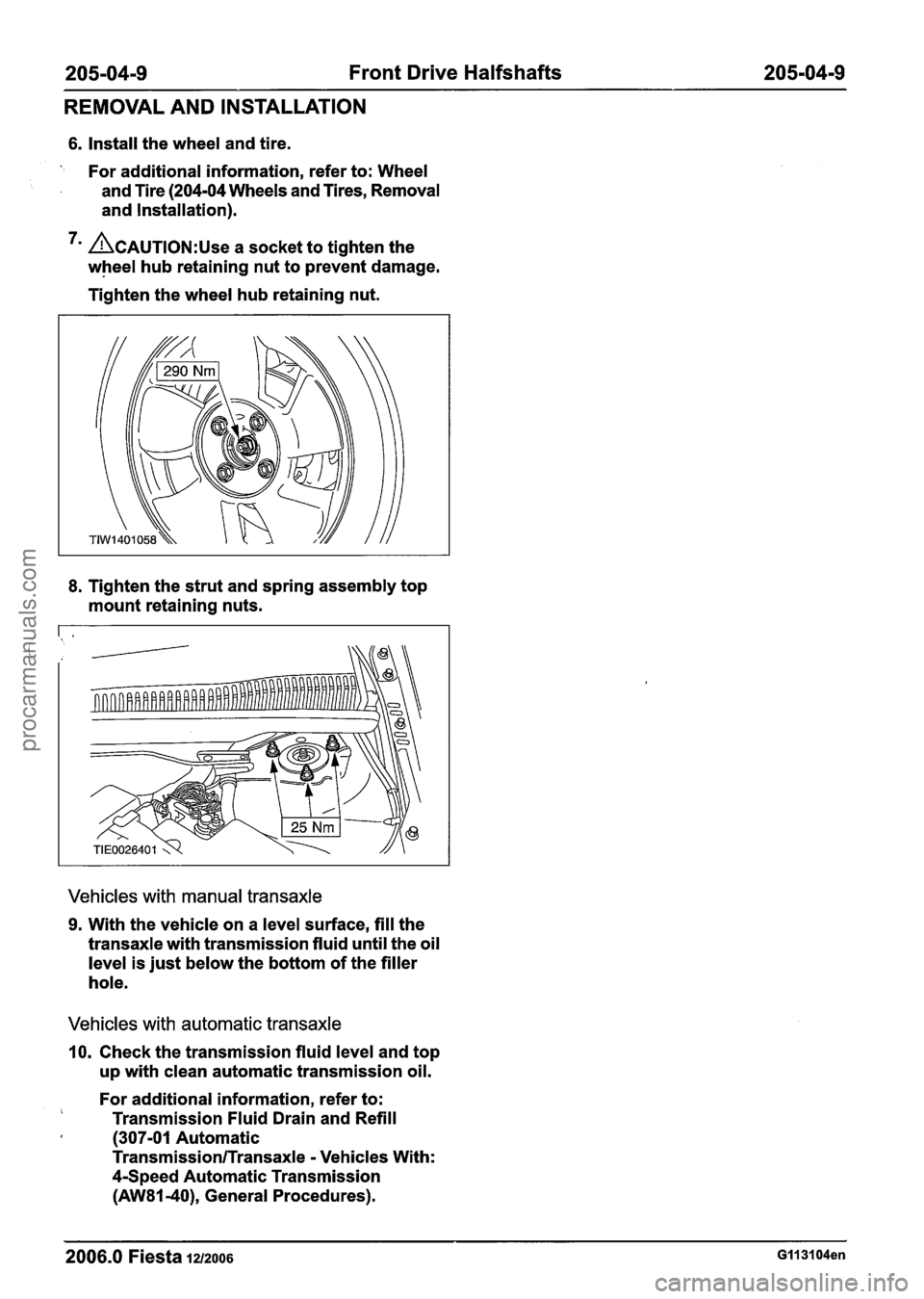
7m CAUTION:^^^ a socket to tighten the
wheel hub retaining nut to prevent damage.
Tighten the wheel hub retaining nut.
8. Tighten the strut and spring assembly top
mount retaining nuts.
Vehicles with manual transaxle
9. With the vehicle on a level surface, fill the
transaxle with transmission fluid until the oil
level is just below the bottom of the filler
hole.
Vehicles with automatic transaxle
10. Check the transmission fluid level and top
up with clean automatic transmission oil.
For additional information, refer to:
Transmission Fluid Drain and Refill I (307-01 Automatic
Transmission/Transaxle - Vehicles With:
4-Speed Automatic Transmission
(AW81-40), General Procedures).
- - -- -
2006.0 Fiesta 1212006 GII 31 04en
procarmanuals.com
Page 165 of 1226
205-04-1 3 Front Drive Halfshafts 205-04-1 3
REMOVAL AND INSTALLATION
Intermediate Shaft
I
Materials
Name Specification
Removal
Manual transmission
1 fluid
A WARN1NG:Refer to the Material Safety Data
Sheets for the Automatic Transmission
Fluid E-AW. Failure to follow this
instruction may result in personal injury.
Certain Transmission and Power Steering
fluids supplied to Ford contain additives
which may cause skin irritation or other
skin reactions after contact.
WSD-M2C200-C
For additional information, refer to: Health
and Safety Precautions
(1 00-00 General
Information, Description and Operation).
See
- Transmission Fluids.
I. Remove the right-hand halfshaft.
, For additional information, refer to: Front
i, Halfshaft RH (205-04 Front Drive Halfshafts,
Removal and Installation).
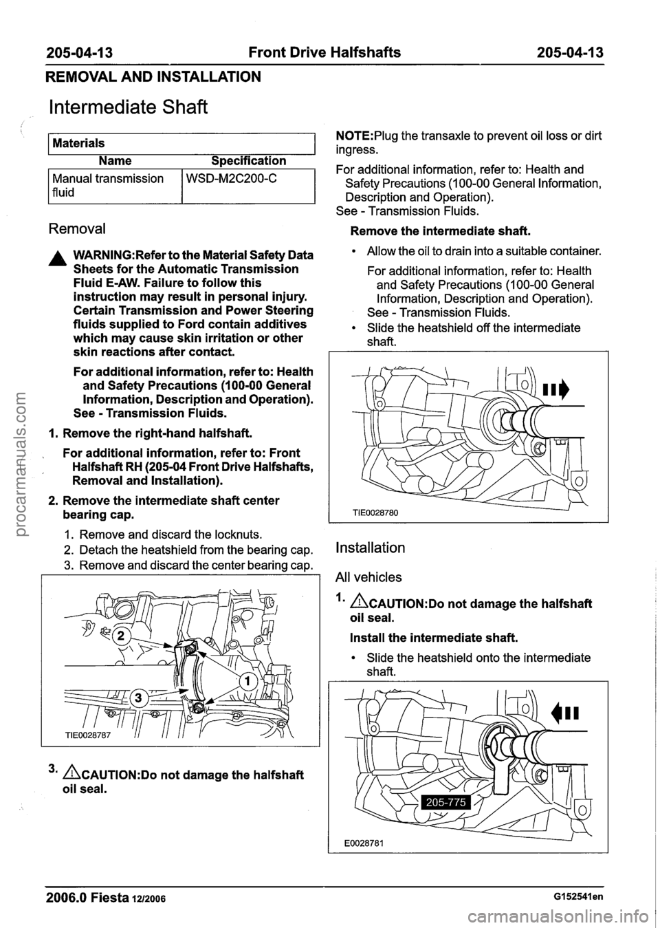
2. Remove the intermediate shaft center
bearing cap.
1. Remove and discard the locknuts.
2. Detach the heatshield from the bearing cap.
3. Remove and discard the center bearing cap.
3m ACAUTION:D~ not damage the halfshaft
oil seal.
N0TE:Plug the transaxle to prevent oil loss or dirt
ingress.
For additional information, refer to: Health and
Safety Precautions
(1 00-00 General Information,
Description and Operation).
See
- Transmission Fluids.
Remove the intermediate shaft.
Allow the oil to drain into a suitable container.
For additional information, refer to: Health
and Safety Precautions
(I 00-00 General
Information, Description and Operation).
See
- Transmission Fluids.
Slide the heatshield off the intermediate
shaft.
Installation
All vehicles
I' ACAUTION:D~ not damage the halfshaft
oil seal.
Install the intermediate shaft.
Slide the heatshield onto the intermediate
shaft.
2006.0 Fiesta 1212006 GI 52541 en
procarmanuals.com
Page 166 of 1226
205-04-1 4 Front Drive Halfshafts 205-04-1 4
REMOVAL AND INSTALLATION
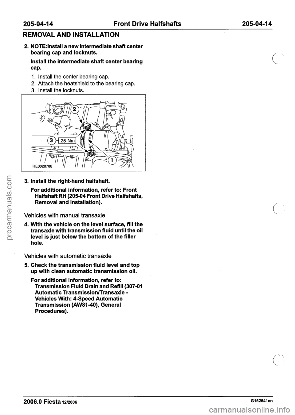
2. N0TE:lnstall a new intermediate shaft center
bearing cap and locknuts.
Install the intermediate shaft center bearing
cap.
I. Install the center bearing cap.
2. Attach the heatshield to the bearing cap.
3. Install the locknuts.
3. Install the right-hand halfshaft.
For additional information, refer to: Front
Halfshaft RH (205-04 Front Drive Halfshafts,
Removal and Installation).
Vehicles with manual transaxle
4. With the vehicle on the level surface, fill the
transaxle with transmission fluid until the oil
level is just below the bottom of the filler
hole.
Vehicles with automatic transaxle
5. Check the transmission fluid level and top
up with clean automatic transmission oil.
For additional information, refer to:
Transmission Fluid Drain and Refill
(307-01
Automatic Transmission/Transaxle -
Vehicles With: 4-Speed Automatic
Transmission
(AW81-40), General
Procedures).
2006.0 Fiesta 1212006 GI 52541 en
procarmanuals.com
Page 198 of 1226
206-00-26 Brake System - General Information 206-00-26
DIAGNOSIS AND TESTING
TEST CONDITIONS DETAILSIRESU LTSIACTIONS
I J6: CHECK BRAKE PEDAL LINKAGE If
rn Disconnect the actuator rod from the pedal pin
and apply the brake pedal fully.
Did the pedal move freely?
-+ Yes
GO to J7.
+ No
REPAIR or INSTALL new brake pedal bush-
ings. REFER to: (206-06 Hydraulic Brake
Actuation)
Brake Pedal
- LHD, Vehicles With: Manual
Transaxle (Removal and Installation),
Brake Pedal
- LHD, Vehicles With: 4-Speed
Automatic Transmission
(AW81-40), Vehicles
With: Automated Gearshift (Removal and
Installation),
Brake Pedal
- RHD (Removal and Installation).
TEST the system for normal operation.
157: CHECK BRAKE PRESSURE CONTROL VALVE I
rn Check the brake pressure control valve for
contamination.
Is the brake fluid contaminated?
+ Yes
INSTALL a new brake pressure control valve.
FILL the brake master cylinder reservoir.
BLEED the brake system. REFER to: (206-00
Brake System
- General Information)
1 Brake System Bleeding (General Procedures),
Brake System Pressure Bleeding (General
Procedures). TEST the system for normal operation.
1 * Ehicle OK.
2006.0 Fiesta 1212006 G28494en
procarmanuals.com
Page 200 of 1226
206-00-28 Brake System - General Information 206-00-28
DIAGNOSIS AND TESTING
PINPOINT TEST L : SLOW OR INCOMPLETE BRAKE PEDAL RETURN
TEST CONDITIONS
DETAILSIRESU LTSIACTIONS /"'
I L1: CHECK FOR BRAKE PEDAL RETURN I[<.
Run the engine at fast idle while making several
brake applications. Pull the brake pedal rear-
ward with approximately 44.5 N
(1 0 lbs) force.
Release the brake pedal and measure the
distance to the floor pan. Make a hard brake
application. Release the brake pedal and
measure the brake pedal to floor pan distance.
The brake pedal should return to its original
position.
Did the brake pedal return to its original posi-
tion?
+ Yes
Vehicle OK.
+ No
GO to L2.
I L2: CHECK FOR BRAKE PEDAL BINDING
1 171 Check the brake pedal for free operation.
I Is the brake pedal operating freely?
+ Yes
I INSTALL a new brake booster. REFER to:
(206-07 Power Brake Actuation)
Brake Booster
- LHD (Removal and lnstallation),
Brake Booster
- RHD (Removal and lnstallation).
TEST the system for normal operation.
+ No
REPAIR or INSTALL new brake pedal bush-
ings. REFER to: (206-06 Hydraulic Brake
Actuation)
Brake Pedal
- LHD, Vehicles With: Manual
Transaxle (Removal and lnstallation),
Brake Pedal
- LHD, Vehicles With: 4-Speed
Automatic Transmission
(AW81-40), Vehicles
With: Automated Gearshift (Removal and
Installation),
Brake Pedal
- RHD (Removal and lnstallation).
TEST the system for normal operation.
Component Tests It is possible that all evidence of fluid leakage may
have washed off if the vehicle has been operated
in rain or snow, as brake fluid is water-soluble.
Hydraulic Leak Check Refill the system, bleed then apply the brakes
several times. Examine the system to verify that
NOTE:Thet-e is a common clutch and brake fluid
the reservoir fluid level is actually dropping. Locate
reservoir, therefore it is possible that a clutch leak
can lead to reduction in the reservoir level.
-- --
2006.0 Fiesta 1212006 G28494en
procarmanuals.com
Page 558 of 1226
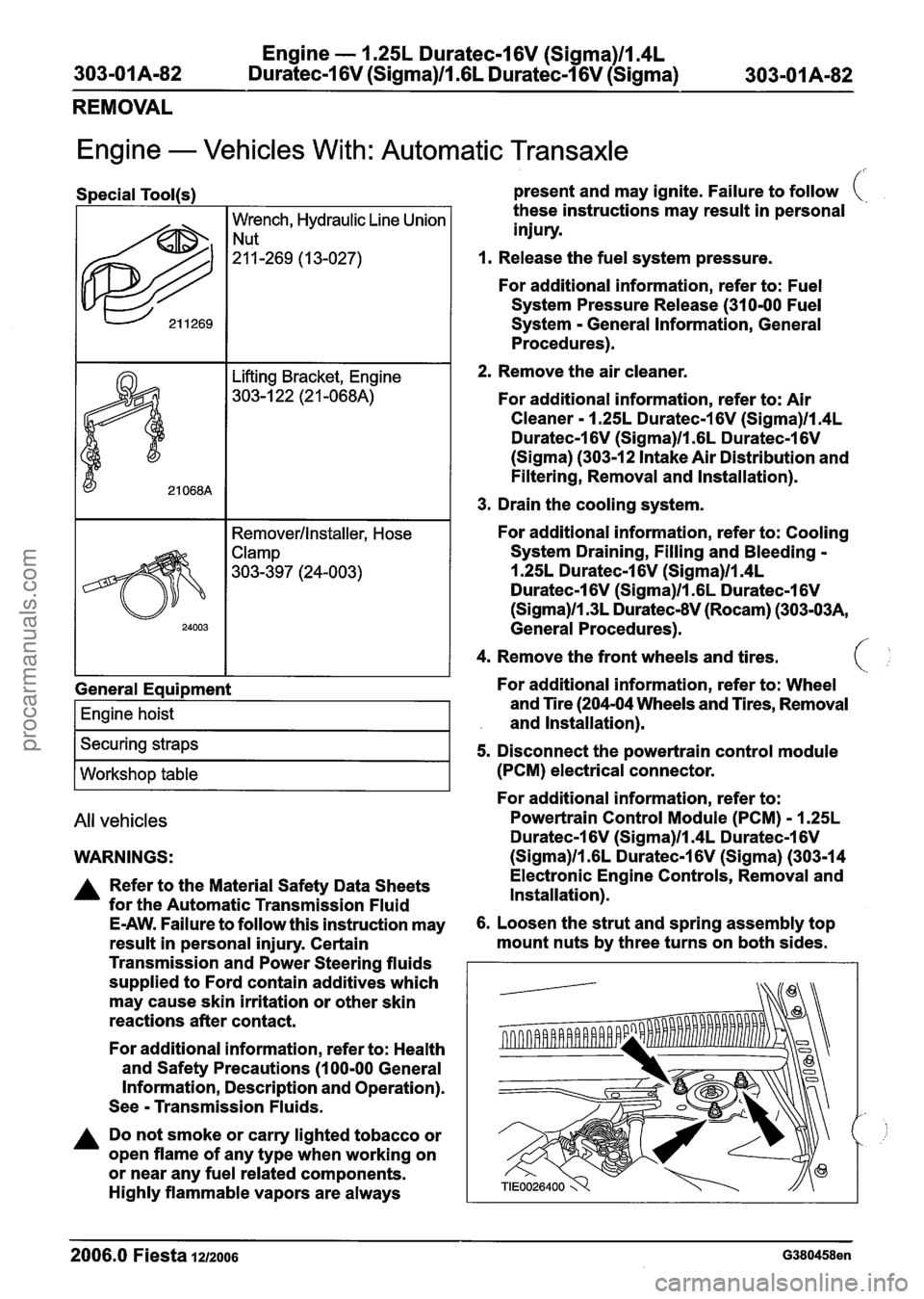
Engine - 1.25L Duratec-1 6V (Sigma)ll.4L
303-0 I Am82 Duratec-1 6V (Sigma)ll .6L Duratec-1 6V (Sigma)
303-01 Am82
REMOVAL
Lifting Bracket, Engine
303-1 22 (21 -068A)
Engine - Vehicles With: Automatic Transaxle
Special Tool(s) present and may ignite. Failure to follow (.
2. Remove the air cleaner.
622
For additional information, refer to: Air
Cleaner - 1.25L Duratec-1 6V (Sigma)ll.4L
Duratec-1 6V (Sigma)/l .6L Duratec-1 6V
(Sigma) (303-12 Intake Air Distribution and
Filtering, Removal and Installation).
I I 1 3. Drain the cooling system.
Wrench, Hydraulic Line Union
"-269 (13-027)
I I Remover/lnstaller, Hose I
these instructions may result in personal
injury.
1. Release the fuel system pressure.
For
additional information, refer to: Fuel
System Pressure Release (31 0-00 Fuel
System - General Information, General
Procedures).
General Eaui~ment
I Engine hoist I
I Securing straps I
I Workshop table I
All vehicles
WARNINGS:
A Refer to the Material Safety Data Sheets
for the Automatic Transmission
Fluid
E-AW. Failure to follow this instruction may
result in personal injury. Certain
Transmission and Power Steering fluids
supplied to Ford contain additives which
may cause skin irritation or other skin
reactions after contact.
For
additional information, refer to: Health
and Safety Precautions (1 00-00 General
Information, Description and Operation).
See
- Transmission Fluids.
A Do not smoke or carry lighted tobacco or
open flame of any type when working on
or near any
fuel related components.
Highly flammable vapors are always
For additional information, refer to: Cooling
System Draining, Filling and Bleeding -
1.25L Duratec-1 6V (Sigma)ll.4L
Duratec-1 6V (Sigma)ll .6L Duratec-1 6V
(Sigma)llm3L Duratec-8V (Rocam) (303-03A,
General Procedures). ,'
4. Remove the front wheels and tires. C'
For additional information, refer to: Wheel
and Tire (204-04 Wheels and Tires, Removal
and Installation).
5. Disconnect the powertrain control module
(PCM) electrical connector.
For
additional information, refer to:
Powertrain
Control Module (PCM) - 1.25L
Duratec-1 6V (Sigma)ll.4L Duratec-1 6V
(Sigma)ll .6L Duratec-1 6V (Sigma) (303-14
Electronic Engine Controls, Removal and
Installation).
6. Loosen the strut and spring assembly top
mount nuts by three turns on both sides.
--
2006.0 Fiesta 1212006 G380458en
procarmanuals.com
Page 616 of 1226
Engine - 1.25L Duratec-1 6V (Sigma)ll.4L
303-01 A-1 40 Duratec-1 6V (Sigma)ll .6L
Duratec-1 6V (Sigma) 303-01 A-1 40
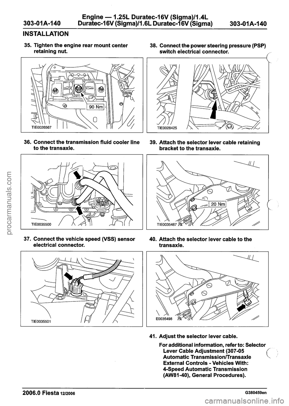
INSTALLATION
35. Tighten the engine rear mount center
retaining nut. 38. Connect the power steering pressure (PSP)
switch electrical connector.
,/'
36. Connect the transmission fluid cooler line 39. Attach the selector lever cable retaining
to the transaxle.
bracket to the transaxle.
37. Connect the vehicle speed (VSS) sensor
40. Attach the selector lever cable to the
electrical connector. transaxle.
41. Adjust the selector lever cable.
For additional information, refer to: Selector
Lever Cable Adjustment (307-05
Automatic
Transmission/Transaxle
External Controls - Vehicles With:
4-Speed Automatic Transmission
(AW81-40), General Procedures).
2006.0 Fiesta 1212006 G380459en
procarmanuals.com