Pcv FORD FIESTA 2007 Workshop Manual
[x] Cancel search | Manufacturer: FORD, Model Year: 2007, Model line: FIESTA, Model: FORD FIESTA 2007Pages: 1226, PDF Size: 61.26 MB
Page 427 of 1226
303-00-5 Engine System - General Information 303-00-5
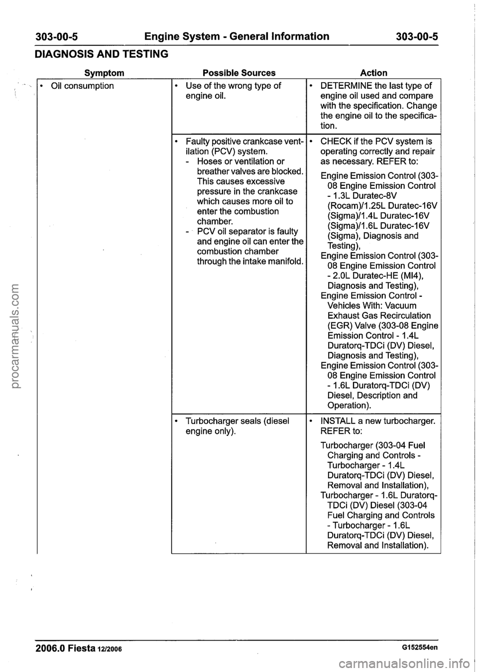
DIAGNOSIS AND TESTING
Symptom
Oil consumption
Possible Sources Action
Use of the wrong type of
engine oil.
Faulty positive crankcase vent-
ilation (PCV) system.
- Hoses or ventilation or
breather valves are blocked.
This causes excessive
pressure in the crankcase
which causes more oil to
enter the combustion
chamber.
- PCV oil separator is faulty
and engine oil can enter the
combustion chamber
through the intake manifold.
Turbocharger seals (diesel
engine only).
DETERMINE the last type of
engine oil used and compare
with the specification. Change
the engine oil to the specifica-
tion.
CHECK if the PCV system is
operating correctly and repair
as necessary. REFER to:
Engine Emission Control (303-
08 Engine Emission Control
- 1.3L Duratec-8V
(Rocam)/l.25L Duratec-1 6V
(Sigma)/l.4L Duratec-1 6V
(Sigma)/l .6L Duratec-1 6V
(Sigma), Diagnosis and
Testing),
Engine Emission Control (303-
08 Engine Emission Control
- 2.OL Duratec-HE (M14),
Diagnosis and Testing),
Engine Emission Control
-
Vehicles With: Vacuum
Exhaust Gas Recirculation
(EGR) Valve (303-08 Engine
Emission Control
- 1.4L
Duratorq-TDCi (DV) Diesel,
Diagnosis and Testing),
Engine Emission Control (303-
08 Engine Emission Control
- 1.6L Duratorq-TDCi (DV)
Diesel, Description and
Operation).
INSTALL a new turbocharger.
REFER to:
Turbocharger (303-04 Fuel
Charging and Controls
-
Turbocharger - I .4L
Duratorq-TDCi (DV) Diesel,
Removal and lnstallation),
Turbocharger
- I .6L Duratorq-
TDCi (DV) Diesel (303-04
Fuel Charging and Controls
- Turbocharger - I .6L
Duratorq-TDCi (DV) Diesel,
Removal and lnstallation).
2006.0 Fiesta 1212006 GI 52554en
procarmanuals.com
Page 484 of 1226
Engine - I .25L Duratec-1 6V (Sigma)llI4L
Duratec-1 6V (Sigma)ll .6L Duratec-I 6V (Sigma)
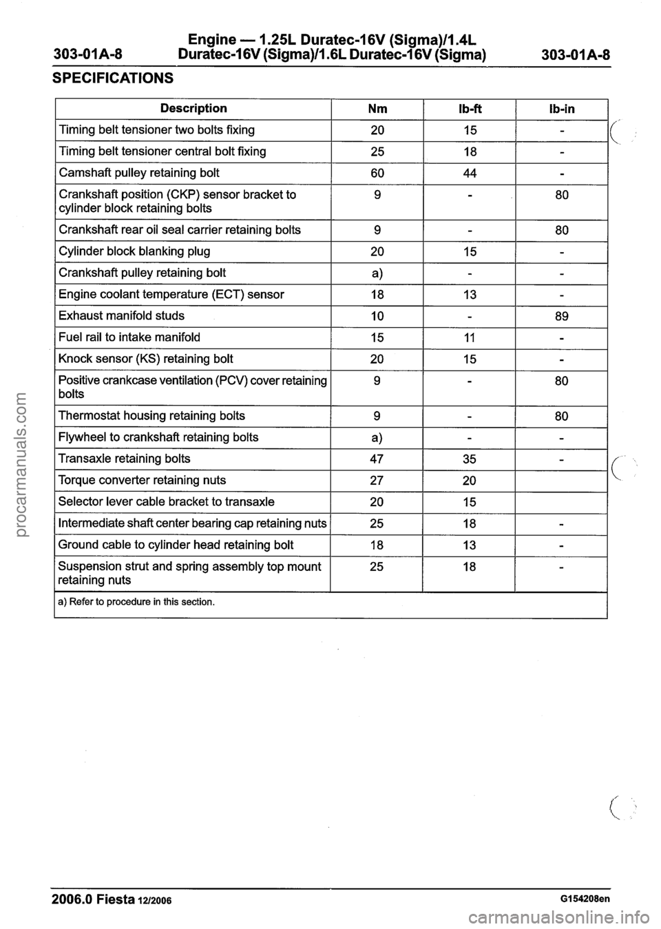
SPECIFICATIONS
1 Description I Nm I Ib-ft I Ib-in I
I Camshaft pulley retaining bolt I 60 I 44 I - I
Timing belt tensioner two bolts fixing
Timing belt tensioner central bolt fixing
Crankshaft position (CKP) sensor bracket to
cylinder block retaining bolts
I Crankshaft rear oil seal carrier retaining bolts I 9 1 - I 80 I
20
25
I Cylinder block blanking plug I 20 I 15 1 - I
I Crankshaft pulley retaining bolt I a) I - I - I
15
18
I Engine coolant temperature (ECT) sensor I 18 I 13 I - I
-
-
I Exhaust manifold studs I 10 I - I 89 I
Positive crankcase ventilation (PCV) cover retaining
1 bolts Fuel
rail to intake manifold
Knock sensor (KS) retaining bolt
I Thermostat housing retaining bolts I 9 I - 1 80 I
I Flywheel to crankshaft retaining bolts I a) I - I - I
15
20
I Selector lever cable bracket to transaxle I 20 I 15 I I
11
15
Transaxle retaining bolts
Torque converter retaining nuts
I Intermediate shaft center bearing cap retaining nuts 1 25 I 18 I - I
-
-
I Ground cable to cylinder head retaining bolt I 18 I 13 I - I
47
27
Suspension strut and spring assembly top mount
retaining nuts
I a) Refer to procedure in this section.
35
20
2006.0 Fiesta 1212006 GI 54208en
-
procarmanuals.com
Page 495 of 1226
Engine - 1.25L Duratec-I 6V (Sigma)ll.4L
303-01A-I 9 Duratec-1 6V (Sigma)/l .6L Duratec-1 6V (Sigma) 303-OIA-I 9
IN-VEHICLE REPAIR
Intake Manifold(21 183 0)
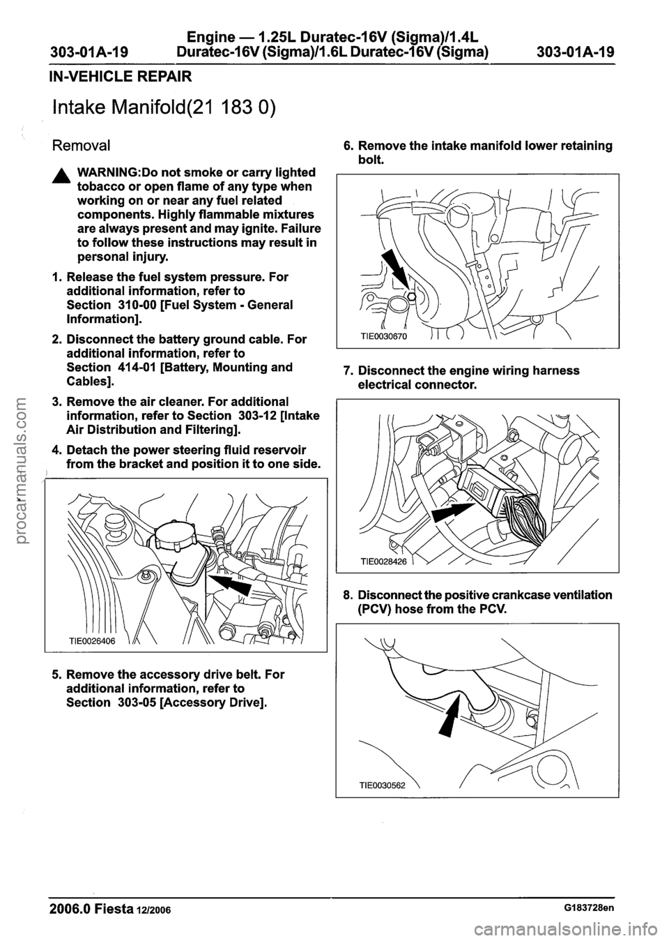
Removal 6. Remove the intake manifold lower retaining
bolt.
A WARNING:Do not smoke or carry lighted
tobacco or open flame of any type when
working on or near any fuel related
components. Highly flammable mixtures
are always present and may ignite. Failure
to follow these instructions may result in
personal injury.
1. Release the fuel system pressure. For
additional information, refer to
Section
31 0-00 [Fuel System - General
Information].
2. Disconnect the battery ground cable. For
additional information, refer to
Section
414-01 [Battery, Mounting and 7. Disconnect the engine wiring harness
Cables]. electrical connector.
3. Remove the air cleaner. For additional
information, refer to Section
303-1 2 [Intake
Air Distribution and Filtering].
4. Detach the power steering fluid reservoir
from the bracket and position
it to one side.
5. Remove the accessory drive belt. For
additional information, refer to
Section
303-05 [Accessory Drive].
8. Disconnect the positive crankcase ventilation
(PCV) hose from the PCV.
2006.0 Fiesta 1212006 GI 83728en
procarmanuals.com
Page 502 of 1226
Engine - 1.25L Duratec-1 6V (Sigma)ll.4L
303-01 A-26 Duratec-1 6V (Sigma)Il.GL Duratec-1 6V (Sigma) 303-01 A-26
IN-VEHICLE REPAIR
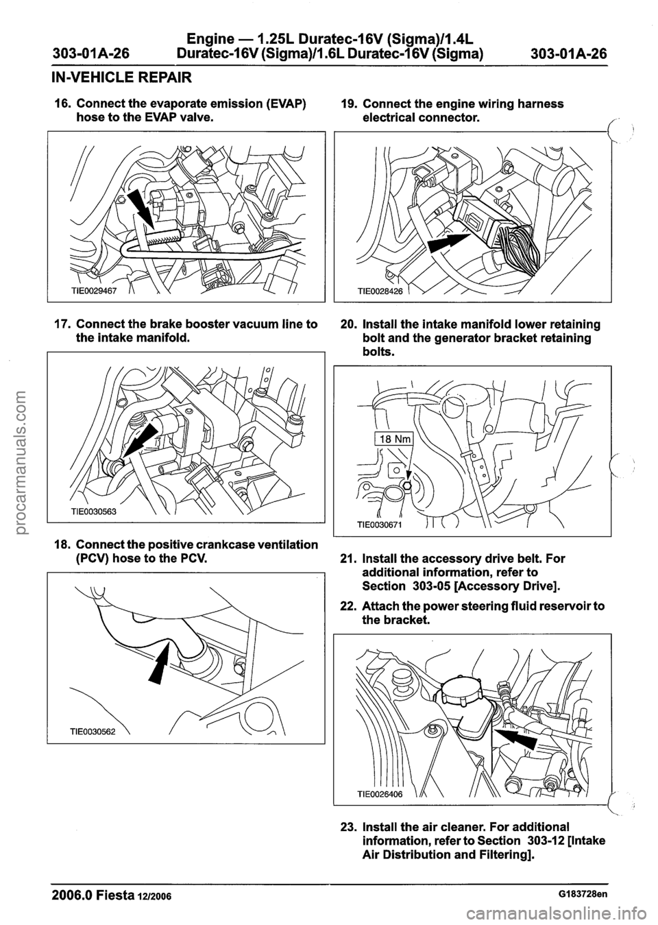
16. Connect the evaporate emission (EVAP)
hose to the EVAP valve.
17. Connect the brake booster vacuum line to
the intake manifold.
19. Connect the engine wiring harness
electrical connector.
20. Install the intake manifold lower retaining
bolt and the generator bracket retaining
bolts.
18. Connect the positive crankcase ventilation
(PCV) hose to the PCV.
21. Install the accessory drive belt. For
additional information, refer to
Section
303-05 [Accessory Drive].
22. Attach the power steering fluid reservoir to
the bracket.
23. Install the air cleaner. For additional
information, refer to Section
3031 2 [Intake
Air Distribution and Filtering].
2006.0 Fiesta 1212006 GI 83728en
procarmanuals.com
Page 531 of 1226
Engine - 1.25L Duratec-1 6V (Sigma)llI4L
303-01 Am55 Duratec-1 6V (Sigma)lll6L Duratec-1 6V (Sigma) 303-01 A-55
IN-VEHICLE REPAIR
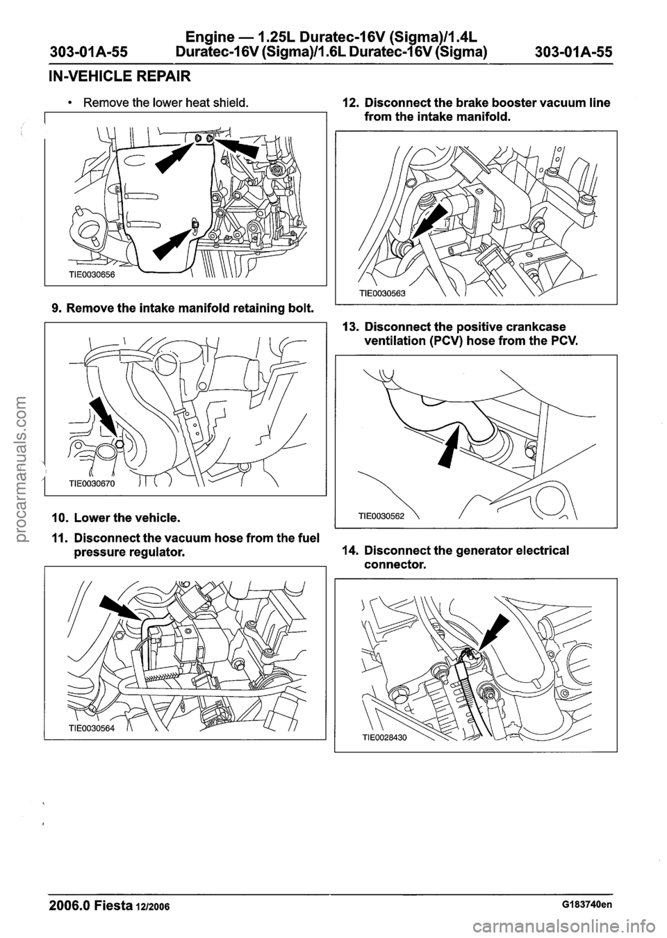
Remove the lower heat shield.
9.
Remove the intake manifold retaining bolt.
10. Lower the vehicle.
12. Disconnect the brake booster vacuum line
from the intake manifold.
13. Disconnect the positive crankcase
ventilation (PCV) hose from the PCV.
11. Disconnect the vacuum hose from the fuel
pressure regulator.
14. Disconnect the generator electrical
connector.
2006.0 Fiesta 1212006 GI 83740en
procarmanuals.com
Page 538 of 1226
Engine - 1.25L Duratec-1 6V (Sigma)ll.4L
Duratec-1 6V (Sigma)ll.GL Duratec-1 6V (Sigma)
IN-VEHICLE REPAIR
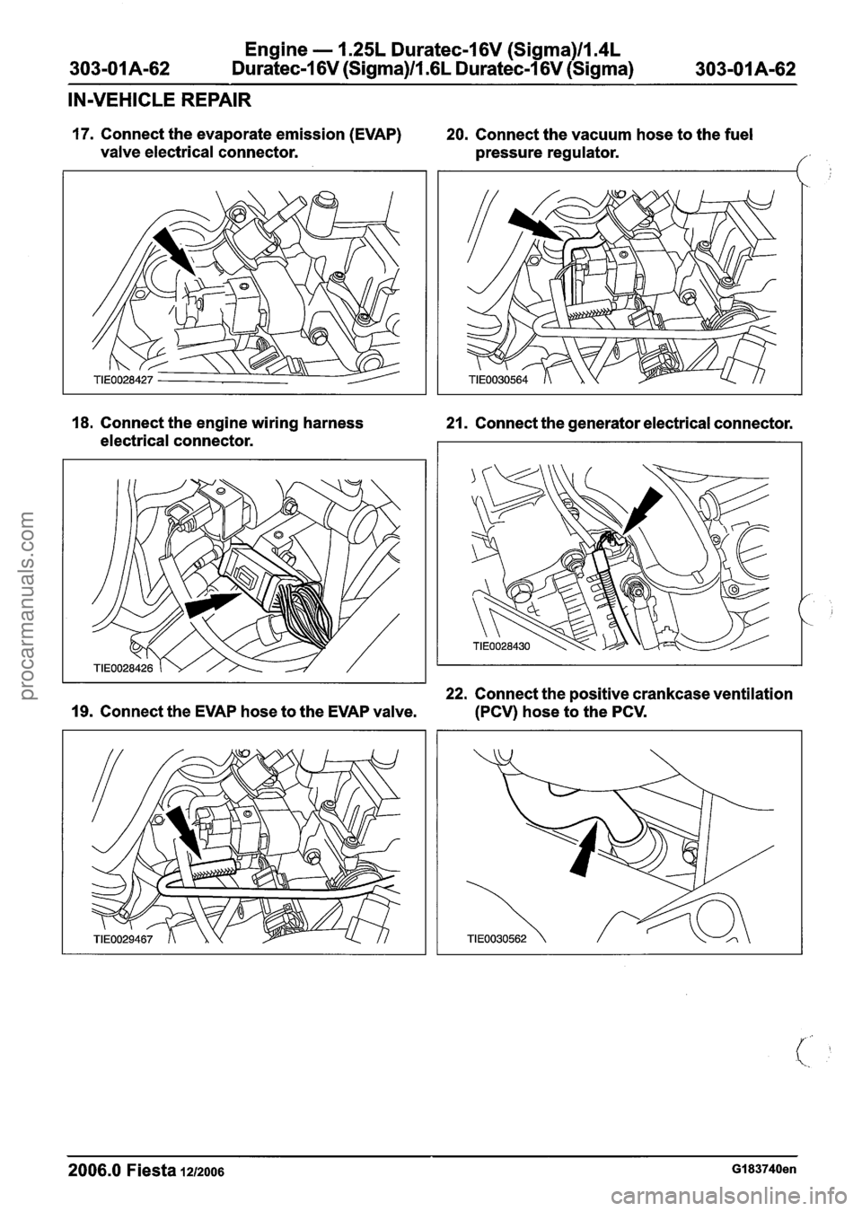
17. Connect the evaporate emission (EVAP) 20. Connect the vacuum hose to the fuel
valve electrical connector. pressure regulator.
18. Connect the engine wiring harness
21. Connect the generator electrical connector.
electrical connector.
22. Connect the positive crankcase ventilation
19. Connect the EVAP hose to the EVAP valve. (PCV) hose to the PCV.
2006.0 Fiesta 1212006 GI 83740en
procarmanuals.com
Page 577 of 1226

Engine - 1.25L Duratec-1 6V (Sigma)llI4L
Duratec-1 6V (Sigma)lI.GL Duratec-1 6V (Sigma) 303-01A-101
DISASSEMBLY
32. Remove the crankshaft timing belt pulley. 35. Disconnect the positive crankcase
ventilation (PCV) hose from the PCV cover.
33. Remove the timing belt rear cover.
34m ACAUTION: ~ee~ the camshaft bearing
caps and the camshafts in order for
installation.
36. Detach the oil level indicator and tube from
the intake manifold.
Detach the knock sensor (KS) electrical
connector from the oil level indicator tube.
Remove the camshafts. 37. Remove the intake manifold lower bolt.
Slacken each camshaft bearing cap retaining
bolt in the sequence shown by one turn until
the camshaft is released.
Remove the camshaft bearing caps.
Remove and discard the camshaft seals.
38.
CAUTIONS:
A~~ace the cylinder head on a suitable
soft surface.
A~emove the cylinder head bolts in the
sequence shown.
2006.0 Fiesta 1212006 G 1 54224en
procarmanuals.com
Page 578 of 1226
Engine - 1.25L Duratec-I 6V (Sigma)ll.4L
303-OIA-I 02 Duratec-1 6V (Sigma)llm6L Duratec-1 6V (Sigma)
DISASSEMBLY
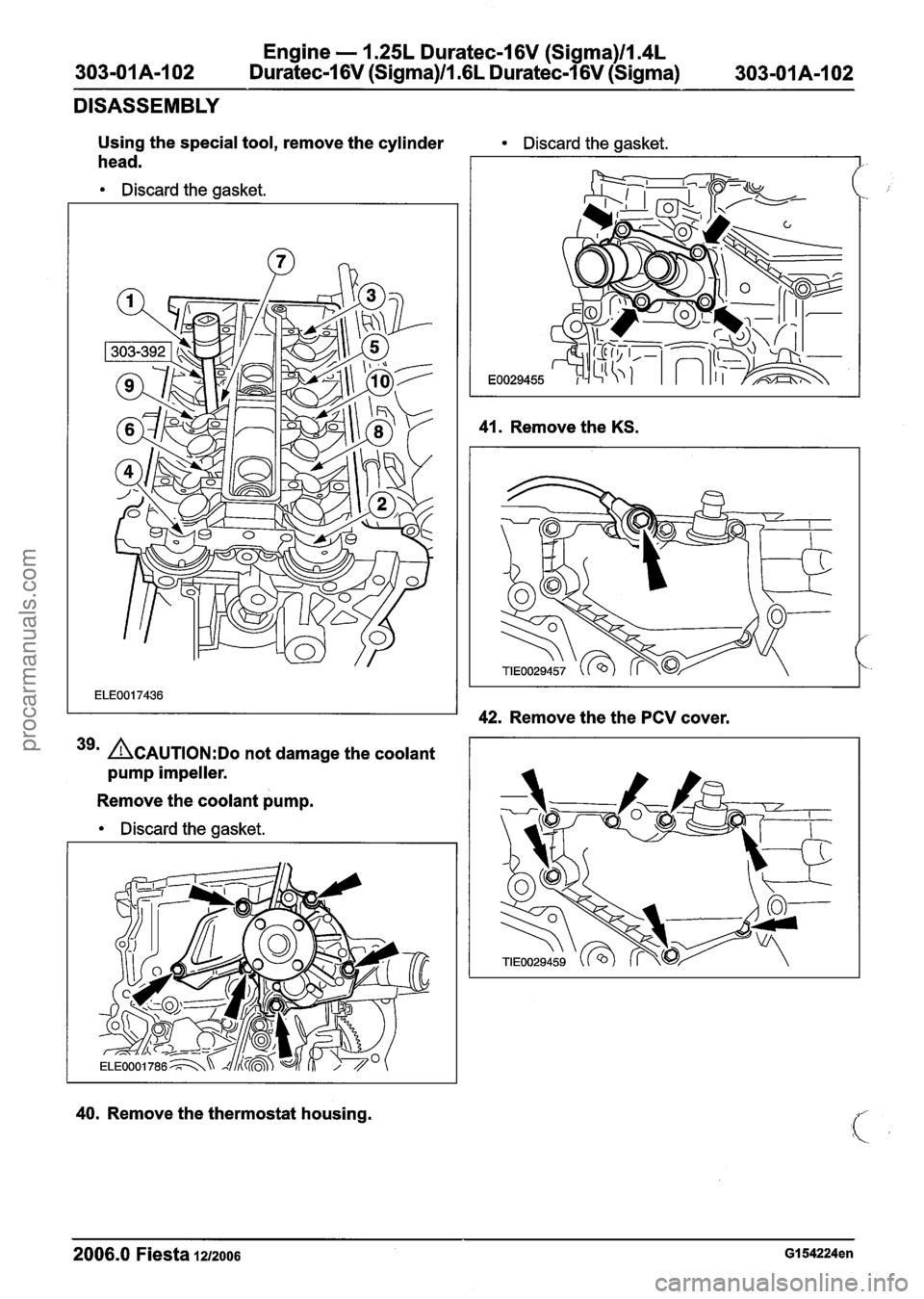
Using the special tool, remove the cylinder
head.
Discard the gasket.
39m ACAUTION:D~ not damage the coolant
pump impeller.
Remove the coolant pump.
Discard the gasket.
Discard the gasket.
41. Remove the KS.
42. Remove the the PCV cover.
40. Remove the thermostat housing.
2006.0 Fiesta iuzoos GI 54224en
procarmanuals.com
Page 588 of 1226
303-01 A-I 12
Engine - 1.25L Duratec-1 6V (Sigma)ll.4L
Duratec-1 6V (Sigma)/lm6L Duratec-1 6V (Sigma)
ASSEMBLY
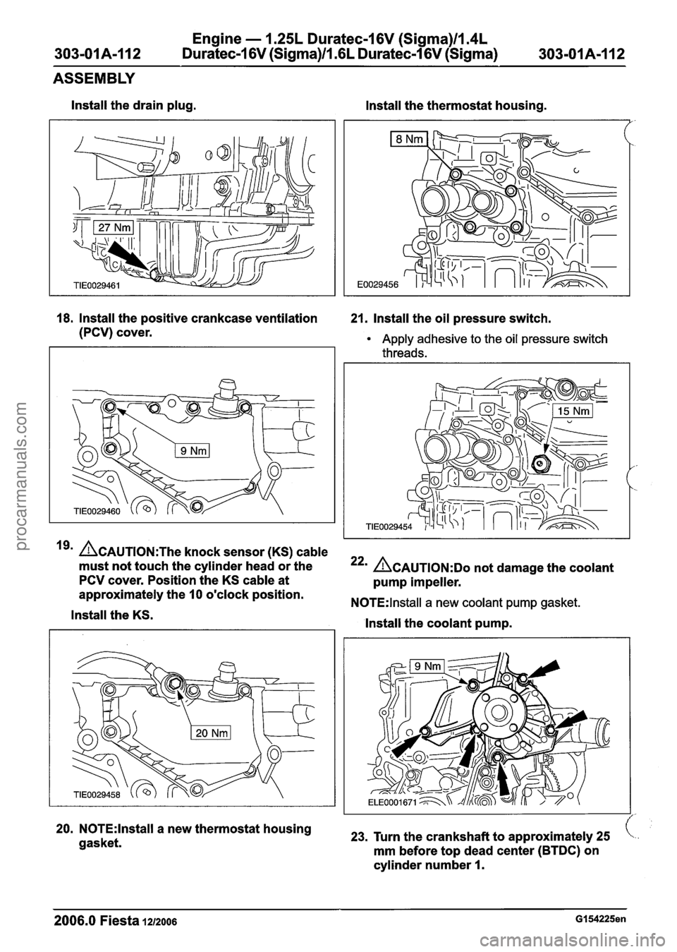
lnstall the drain plug.
lnstall the thermostat housing.
18. Install the positive crankcase ventilation 21. Install the oil pressure switch.
(PCV) cover.
Apply adhesive to the oil pressure switch
threads.
19' ~CAUTION:T~~ knock sensor (KS) cable
must not touch the cylinder head or the
PCV cover. Position the KS cable at
approximately the
10 o'clock position.
lnstall the KS.
20. N0TE:lnstall a new thermostat housing
gasket.
22' ACAUTION:D~ not damage the coolant
pump impeller.
N0TE:lnstall a new coolant pump gasket.
lnstall the coolant pump.
23, Turn the crankshaft to approximately 25
mm before top dead center (BTDC) on
cylinder number
I.
2006.0 Fiesta 1212006 GI 54225en
procarmanuals.com
Page 589 of 1226
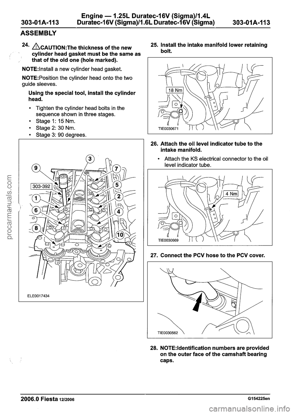
Engine - 1.25L Duratec-1 6V (Sigma)ll.4L
303-01A-I13 Duratec-1 6V (Sigma)/l .6L Duratec-1 6V (Sigma)
303-01 A-I 13
ASSEMBLY
24n ACAUTION:T~~ thickness of the new 25.
Install the intake manifold lower retaining
, cylinder head gasket must be the same as bolt.
I , that
of the old one (hole marked).
N0TE:lnstall a new cylinder head gasket.
N0TE:Position the cylinder head onto the two
guide sleeves.
Using the special tool, install the cylinder
head.
Tighten the cylinder head bolts in the
sequence shown in three stages.
Stage 1: 15 Nm.
Stage2: 30 Nm.
Stage 3: 90 degrees.
26. Attach the oil level indicator tube to the
intake manifold.
Attach the KS electrical connector to the oil
level indicator tube.
27. Connect the PCV hose to the PCV cover.
28. N0TE:ldentification numbers are provided
on the outer face of the camshaft bearing
caps.
2006.0 Fiesta 1212006 GI 54225en
procarmanuals.com