clock FORD FUSION HYBRID 2014 Owners Manual
[x] Cancel search | Manufacturer: FORD, Model Year: 2014, Model line: FUSION HYBRID, Model: FORD FUSION HYBRID 2014Pages: 473, PDF Size: 5.93 MB
Page 27 of 473
Left-Hand Side Turn counterclockwise to lock and
clockwise to unlock.
Right-Hand Side Turn clockwise to lock and
counterclockwise to unlock.
24Child Safety
Page 166 of 473
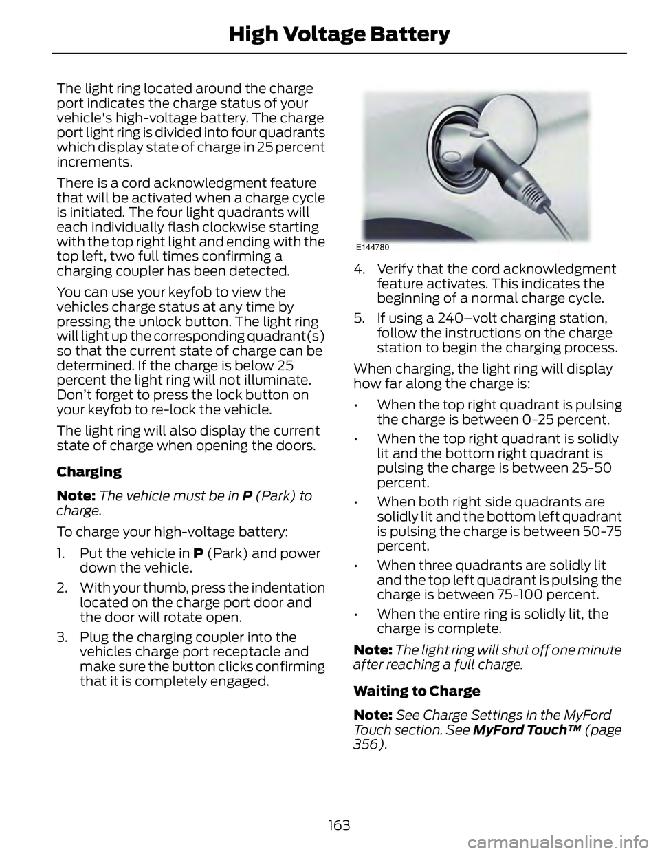
The light ring located around the charge
port indicates the charge status of your
vehicle's high-voltage battery. The charge
port light ring is divided into four quadrants
which display state of charge in 25 percent
increments.
There is a cord acknowledgment feature
that will be activated when a charge cycle
is initiated. The four light quadrants will
each individually flash clockwise starting
with the top right light and ending with the
top left, two full times confirming a
charging coupler has been detected.
You can use your keyfob to view the
vehicles charge status at any time by
pressing the unlock button. The light ring
will light up the corresponding quadrant(s)
so that the current state of charge can be
determined. If the charge is below 25
percent the light ring will not illuminate.
Don’t forget to press the lock button on
your keyfob to re-lock the vehicle.
The light ring will also display the current
state of charge when opening the doors.
Charging
Note: The vehicle must be in P (Park) to
charge.
To charge your high-voltage battery:
1. Put the vehicle in P (Park) and power
down the vehicle.
2. With your thumb, press the indentation
located on the charge port door and
the door will rotate open.
3. Plug the charging coupler into the
vehicles charge port receptacle and
make sure the button clicks confirming
that it is completely engaged. E144780
4. Verify that the cord acknowledgment
feature activates. This indicates the
beginning of a normal charge cycle.
5. If using a 240–volt charging station,
follow the instructions on the charge
station to begin the charging process.
When charging, the light ring will display
how far along the charge is:
• When the top right quadrant is pulsing
the charge is between 0-25 percent.
• When the top right quadrant is solidly
lit and the bottom right quadrant is
pulsing the charge is between 25-50
percent.
• When both right side quadrants are
solidly lit and the bottom left quadrant
is pulsing the charge is between 50-75
percent.
• When three quadrants are solidly lit
and the top left quadrant is pulsing the
charge is between 75-100 percent.
• When the entire ring is solidly lit, the
charge is complete.
Note: The light ring will shut off one minute
after reaching a full charge.
Waiting to Charge
Note: See Charge Settings in the MyFord
Touch section. See MyFord Touch™ (page
356).
163High Voltage Battery
Page 167 of 473
When Value Charge has been selected
charging may not begin upon plugging in.
The vehicle may delay charging to take
advantage of off-peak electricity rates. The
vehicle will optimize the charge schedule
to be complete by the next GO Time.
When waiting to charge (not actively
charging), the light ring will indicate the
present state of charge of the high voltage
battery as follows:
• When the top right quadrant is shut off
the charge is between 0–25 percent.
• When the top right quadrant is solidly
lit and the bottom right quadrant is
shut off the charge is between 25–50
percent.
• When both right side quadrants are
solidly lit and the bottom left quadrant
is shut off the charge is between 50–75
percent.
• When three quadrants are solidly lit
and the top left quadrant is shut off the
charge is between 75–100 percent.
• When the entire ring is solidly lit, the
charge is 100 percent.
Note: When the vehicle is Waiting to
Charge the light ring will shut off one minute
after displaying the present state of charge.
When the vehicle automatically begins
charging the light ring will turn on and
display how far along the charge is per the
section above.
Note: If a vehicle charging system fault is
detected at any point in a charge cycle the
entire light ring will flash continuously for
one minute and then shut off. If this
happens unplug, and then re-plug the
charging coupler into the charge port
receptacle. If the problem persists contact
your authorized dealer.
The light ring illumination conditions can
be modified. See Charge Port Light Ring
Settings in the MyFord Touch section. See
MyFord Touch™ (page 356). Disconnecting the Charging Coupler
Note: Do not pull the wall plug from the
wall while the vehicle is charging. Doing so
may damage the outlet and the cord.
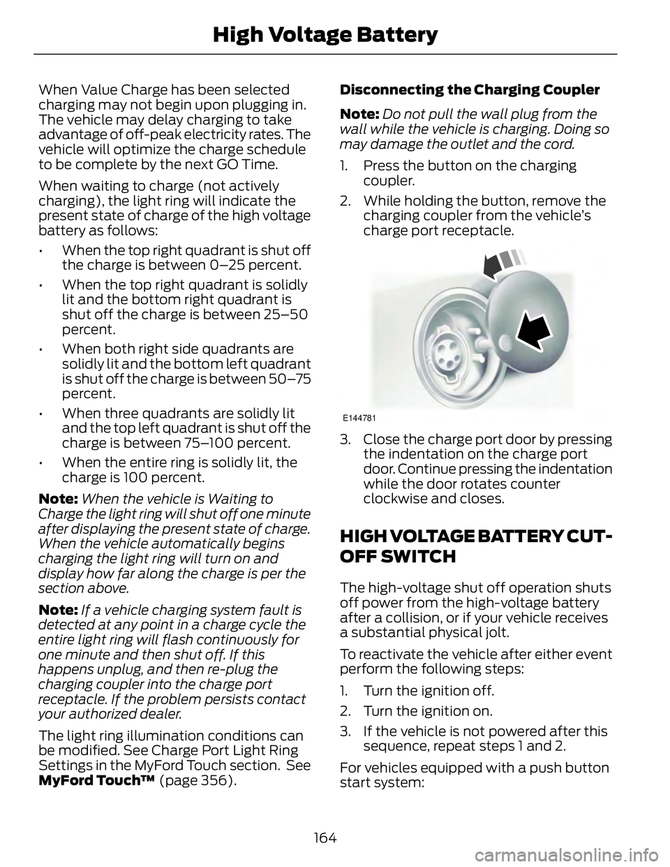
1. Press the button on the charging
coupler.
2. While holding the button, remove the
charging coupler from the vehicle’s
charge port receptacle. E144781
3. Close the charge port door by pressing
the indentation on the charge port
door. Continue pressing the indentation
while the door rotates counter
clockwise and closes.
HIGH VOLTAGE BATTERY CUT-
OFF SWITCH The high-voltage shut off operation shuts
off power from the high-voltage battery
after a collision, or if your vehicle receives
a substantial physical jolt.
To reactivate the vehicle after either event
perform the following steps:
1. Turn the ignition off.
2. Turn the ignition on.
3. If the vehicle is not powered after this
sequence, repeat steps 1 and 2.
For vehicles equipped with a push button
start system:
164High Voltage Battery
Page 254 of 473
Because your vehicle’s engine is
electronically-controlled by a computer,
some engine control settings are
maintained by power from the low-voltage
battery. Some engine computer settings,
like the idle trim and fuel trim strategy,
optimize the driveability and performance
of the engine. The clock and radio station
presets are also maintained in memory by
power from the low-voltage battery. These
settings are erased when a technician
disconnects and connects the low-voltage
battery.
Complete the following procedure in order
to restore the settings:
1. With the vehicle at a complete stop,
set the parking brake.
2. Shift the transmission into P (Park)
3. Turn off all accessories.
4. Step on the brake pedal and start the
vehicle.
5. Run the engine until it reaches normal
operating temperature. While the
engine is warming up, complete the
following: Reset the clock. See Audio
System (page 299). Reset the power
windows bounce-back feature. See
Windows and Mirrors (page 74).
Reset the radio station presets. See
Audio System (page 299).
6. Allow the engine to idle for at least one
minute. If the engine turns off, step on
the accelerator to start the engine.
7. While the engine is running, step on the
brake pedal and shift the transmission
to N.
8. Allow the engine to run for at least one
minute by pressing on the accelerator
pedal.
9. Drive the vehicle at least 10 miles (16
kilometers) to completely relearn the
idle and fuel trim strategy. Note: If you do not allow the engine to
relearn the idle and fuel trim strategy, the
idle quality of your vehicle may be adversely
affected until the engine computer
eventually relearns the idle trim and fuel
trim strategy.
Note: Always dispose of automotive
batteries in a responsible manner. Follow
your local authorized standards for disposal.
Call your local authorized recycling center
to find out more about recycling automotive
batteries.
Note: It is recommended that the negative
battery cable terminal be disconnected from
the battery if you plan to store your vehicle
for an extended period of time.
CHECKING THE WIPER
BLADES E142463
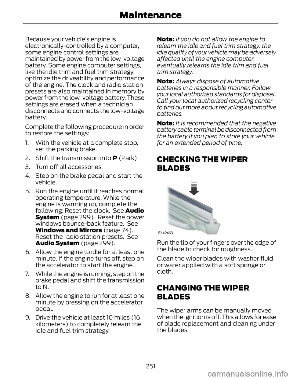
Run the tip of your fingers over the edge of
the blade to check for roughness.
Clean the wiper blades with washer fluid
or water applied with a soft sponge or
cloth.
CHANGING THE WIPER
BLADES The wiper arms can be manually moved
when the ignition is off. This allows for ease
of blade replacement and cleaning under
the blades.
251Maintenance
Page 256 of 473

ADJUSTING THE HEADLAMPS Vertical Aim Adjustment The headlamps on your vehicle are
properly aimed at the assembly plant. If
your vehicle has been in an accident, the
alignment of your headlamps should be
checked by your authorized dealer.
Headlamp Aiming Target E142592
8 feet (2.4 meters)A
Center height of lamp to groundB
25 feet (7.6 meters)C
Horizontal reference lineD
Vertical Aim Adjustment Procedure
1. Park the vehicle directly in front of a
wall or screen on a level surface,
approximately 25 feet (7.6 meters)
away.
2. Measure the height of the headlamp
bulb center from the ground and mark
an 8 foot (2.4 meter) horizontal
reference line on the vertical wall or
screen at this height.
Note: To see a clearer light pattern for
adjusting, you may want to block the light
from one headlamp while adjusting the
other. 3. Turn on the low beam headlamps to
illuminate the wall or screen and open
the hood. E142465
4. On the wall or screen you will observe
a flat zone of high intensity light
located at the top of the right hand
portion of the beam pattern. If the top
edge of the high intensity light zone is
not at the horizontal reference line, the
headlamp will need to be adjusted.
E145594
5. Locate the vertical adjuster on each
headlamp. Using a Phillips #2
screwdriver, turn the adjuster either
clockwise or counterclockwise in order
to adjust the vertical aim of the
headlamp. The horizontal edge of the
brighter light should touch the
horizontal reference line.
6. Close the hood and turn off the lamps.
253Maintenance
Page 259 of 473
Examples of unacceptable moisture
(usually caused by a lamp water leak) are:
• Water puddle inside the lamp.
• Large water droplets, drip marks or
streaks present on the interior of the
lens.
Take your vehicle to an authorized dealer
for service if any of the above conditions
of unacceptable moisture are present.
Replacing the Headlamp Bulbs WARNING
Handle a halogen headlamp bulb
carefully and keep out of children’s
reach. Grasp the bulb by only its
plastic base and do not touch the glass.
The oil from your hand could cause the
bulb to break the next time the headlamps
are operated.
Note: If the bulb is accidentally touched, it
should be cleaned with rubbing alcohol
before being used.
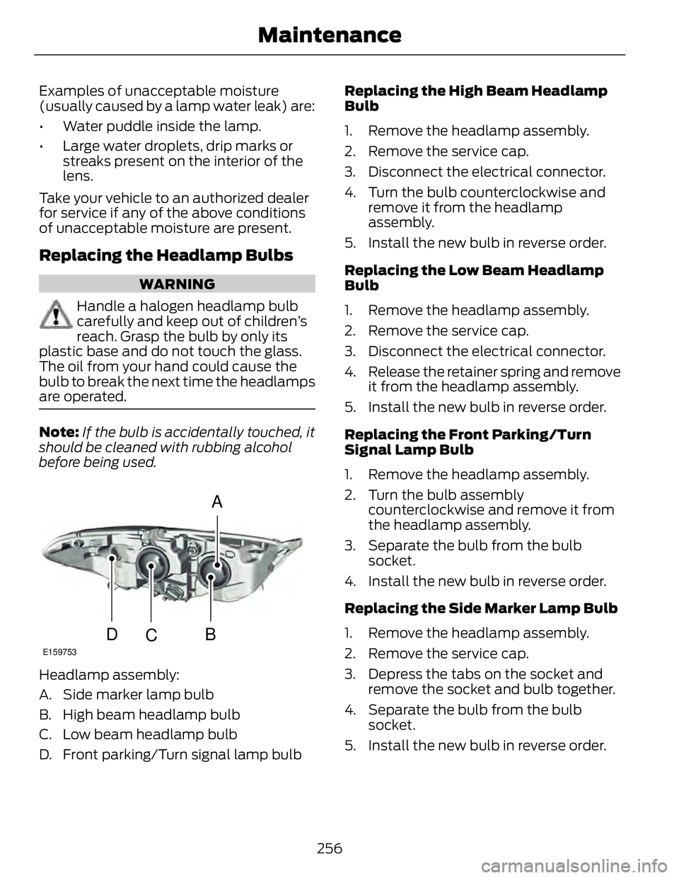
A
B
CDE159753
Headlamp assembly:
A. Side marker lamp bulb
B. High beam headlamp bulb
C. Low beam headlamp bulb
D. Front parking/Turn signal lamp bulb Replacing the High Beam Headlamp
Bulb
1. Remove the headlamp assembly.
2. Remove the service cap.
3. Disconnect the electrical connector.
4. Turn the bulb counterclockwise and
remove it from the headlamp
assembly.
5. Install the new bulb in reverse order.
Replacing the Low Beam Headlamp
Bulb
1. Remove the headlamp assembly.
2. Remove the service cap.
3. Disconnect the electrical connector.
4. Release the retainer spring and remove
it from the headlamp assembly.
5. Install the new bulb in reverse order.
Replacing the Front Parking/Turn
Signal Lamp Bulb
1. Remove the headlamp assembly.
2. Turn the bulb assembly
counterclockwise and remove it from
the headlamp assembly.
3. Separate the bulb from the bulb
socket.
4. Install the new bulb in reverse order.
Replacing the Side Marker Lamp Bulb
1. Remove the headlamp assembly.
2. Remove the service cap.
3. Depress the tabs on the socket and
remove the socket and bulb together.
4. Separate the bulb from the bulb
socket.
5. Install the new bulb in reverse order.
256Maintenance
Page 260 of 473
Replacing the Tail, Brake, High-
Mount Brake Lamp, and Turn
Signal Lamp Bulbs These lamps are designed with LED light
sources. For replacement, see your
authorized dealer.
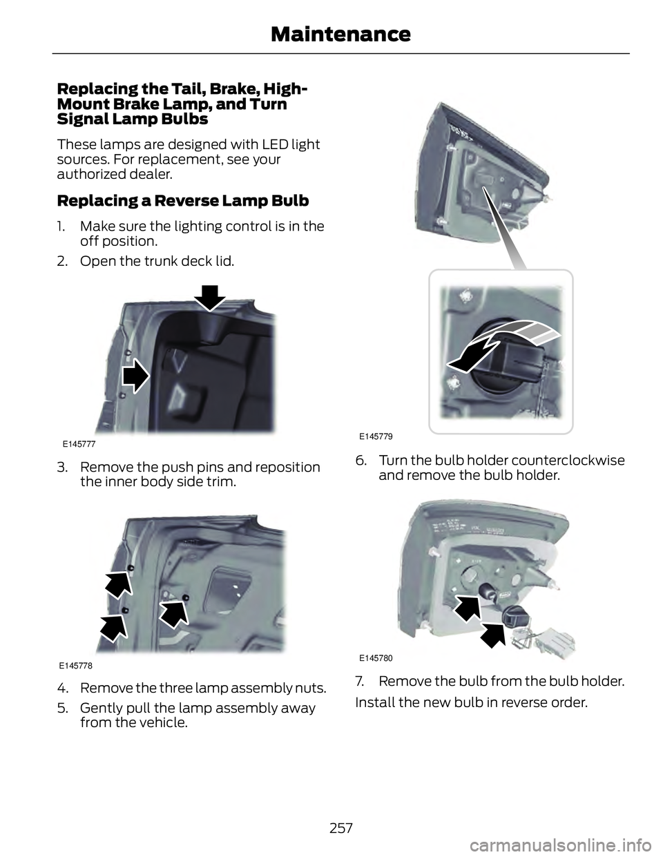
Replacing a Reverse Lamp Bulb 1. Make sure the lighting control is in the
off position.
2. Open the trunk deck lid. E145777
3. Remove the push pins and reposition
the inner body side trim.
E145778
4. Remove the three lamp assembly nuts.
5. Gently pull the lamp assembly away
from the vehicle. E145779
6. Turn the bulb holder counterclockwise
and remove the bulb holder.
E145780
7. Remove the bulb from the bulb holder.
Install the new bulb in reverse order.
257Maintenance
Page 272 of 473
First Stage: Reinflating the Tire
with Sealing Compound and Air WARNINGS
Do not stand directly over the kit
while inflating the tire. If you notice
any unusual bulges or deformations
in the tire's sidewall during inflation, stop
and call roadside assistance.
If the tire doesn't inflate to the
recommended tire pressure within
15 minutes, stop and call roadside
assistance.
Preparation: Park the vehicle in a safe, level
and secure area, away from moving traffic.
Turn the hazard lights on. Apply the parking
brake and turn the engine off. Inspect the
flat tire for visible damage.
Sealant compound contains latex. To
avoid any allergic reactions, use the
non-latex gloves located in the accessory
box on the underside of the kit housing.
Do not remove any foreign object that has
pierced the tire. If a puncture is located in
the tire sidewall, stop and call roadside
assistance.
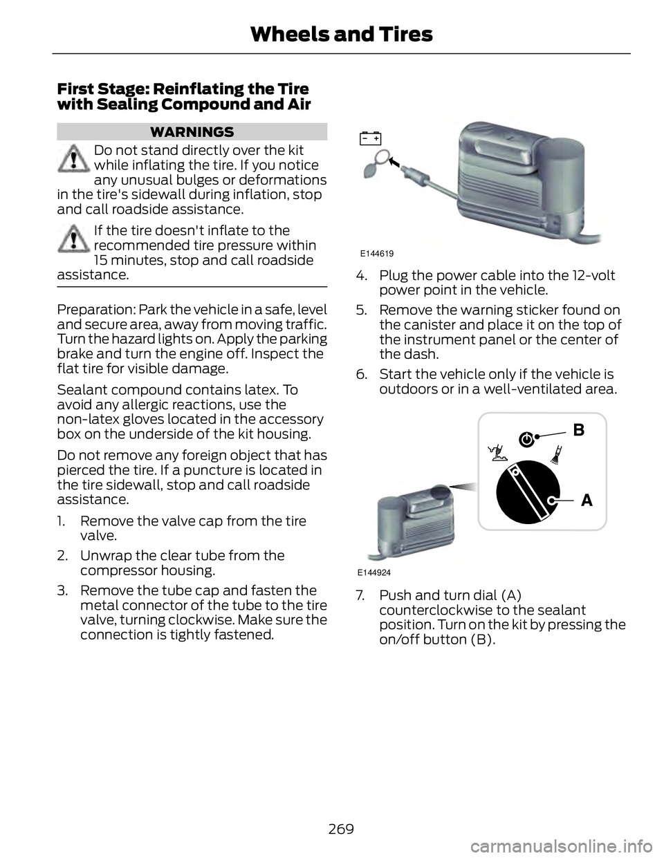
1. Remove the valve cap from the tire
valve.
2. Unwrap the clear tube from the
compressor housing.
3. Remove the tube cap and fasten the
metal connector of the tube to the tire
valve, turning clockwise. Make sure the
connection is tightly fastened. E144619
4. Plug the power cable into the 12-volt
power point in the vehicle.
5. Remove the warning sticker found on
the canister and place it on the top of
the instrument panel or the center of
the dash.
6. Start the vehicle only if the vehicle is
outdoors or in a well-ventilated area.
E144924
7. Push and turn dial (A)
counterclockwise to the sealant
position. Turn on the kit by pressing the
on/off button (B).
269Wheels and Tires
Page 273 of 473
E144621
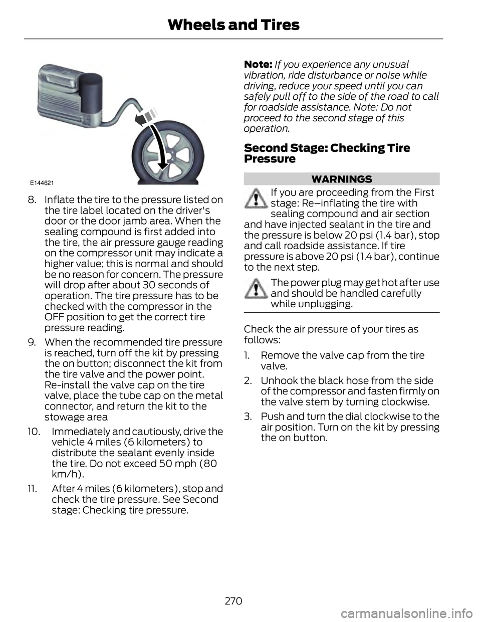
8. Inflate the tire to the pressure listed on
the tire label located on the driver's
door or the door jamb area. When the
sealing compound is first added into
the tire, the air pressure gauge reading
on the compressor unit may indicate a
higher value; this is normal and should
be no reason for concern. The pressure
will drop after about 30 seconds of
operation. The tire pressure has to be
checked with the compressor in the
OFF position to get the correct tire
pressure reading.
9. When the recommended tire pressure
is reached, turn off the kit by pressing
the on button; disconnect the kit from
the tire valve and the power point.
Re-install the valve cap on the tire
valve, place the tube cap on the metal
connector, and return the kit to the
stowage area
10. Immediately and cautiously, drive the
vehicle 4 miles (6 kilometers) to
distribute the sealant evenly inside
the tire. Do not exceed 50 mph (80
km/h).
11. After 4 miles (6 kilometers), stop and
check the tire pressure. See Second
stage: Checking tire pressure. Note: If you experience any unusual
vibration, ride disturbance or noise while
driving, reduce your speed until you can
safely pull off to the side of the road to call
for roadside assistance. Note: Do not
proceed to the second stage of this
operation.
Second Stage: Checking Tire
Pressure WARNINGS
If you are proceeding from the First
stage: Re–inflating the tire with
sealing compound and air section
and have injected sealant in the tire and
the pressure is below 20 psi (1.4 bar), stop
and call roadside assistance. If tire
pressure is above 20 psi (1.4 bar), continue
to the next step.
The power plug may get hot after use
and should be handled carefully
while unplugging.
Check the air pressure of your tires as
follows:
1. Remove the valve cap from the tire
valve.
2. Unhook the black hose from the side
of the compressor and fasten firmly on
the valve stem by turning clockwise.
3. Push and turn the dial clockwise to the
air position. Turn on the kit by pressing
the on button.
270Wheels and Tires
Page 305 of 473
MEDIA: Press this button to access your auxiliary input jack or switch between
devices you plug into the input jack or USB port.R
Clock: Press this button to access the clock setting. Use the center arrow
controls to change the hours and minutes. You can also set the clock by pressing
the MENU button and scrolling to Clock Settings.S
RADIO: Press this button to listen to the radio or change radio frequencies
bands. Press the function buttons below the radio screen to select different
radio functions.T
SIRIUS: Press this button to listen to SIRIUS satellite radio.U
AUDIO UNIT - VEHICLES WITH:
PREMIUM AM/FM/CD WARNING
Driving while distracted can result in
loss of vehicle control, crash and
injury. We strongly recommend that
you use extreme caution when using any
device that may take your focus off the
road. Your primary responsibility is the safe
operation of your vehicle. We recommend
against the use of any hand-held device
while driving and encourage the use of
voice-operated systems when possible.
Make sure you are aware of all applicable
local laws that may affect the use of
electronic devices while driving. Note: The MyFord Touch system controls
most of the audio features. See MyFord
Touch™ (page 356).
302Audio System