FORD GRANADA 1985 Service Repair Manual
Manufacturer: FORD, Model Year: 1985, Model line: GRANADA, Model: FORD GRANADA 1985Pages: 255, PDF Size: 14.98 MB
Page 171 of 255
12•14Bodywork and fittings
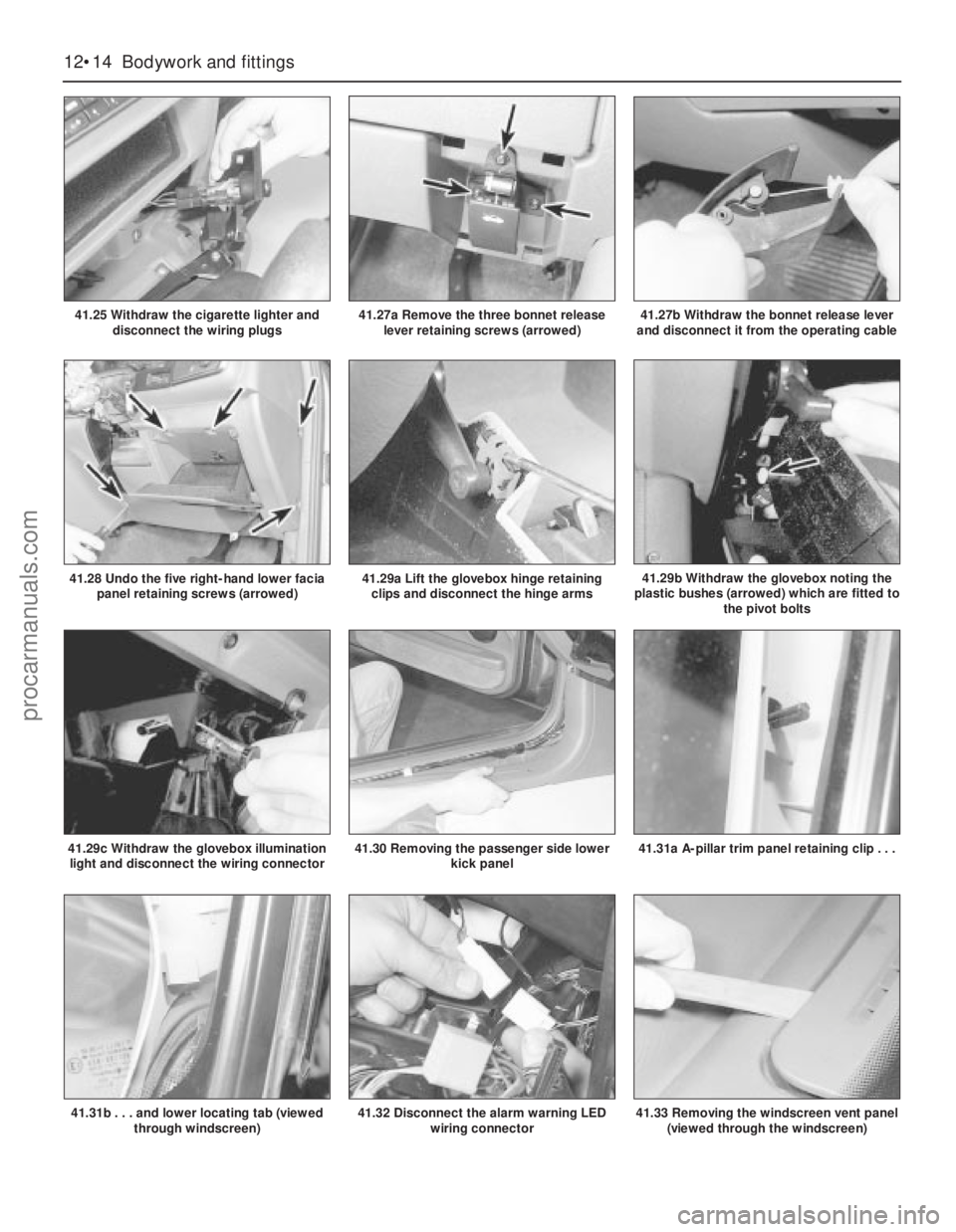
41.25 Withdraw the cigarette lighter and
disconnect the wiring plugs
41.30 Removing the passenger side lower
kick panel
41.29a Lift the glovebox hinge retaining
clips and disconnect the hinge arms41.29b Withdraw the glovebox noting the
plastic bushes (arrowed) which are fitted to
the pivot bolts
41.29c Withdraw the glovebox illumination
light and disconnect the wiring connector
41.28 Undo the five right-hand lower facia
panel retaining screws (arrowed)
41.31a A-pillar trim panel retaining clip . . .
41.31b . . . and lower locating tab (viewed
through windscreen)
41.27a Remove the three bonnet release
lever retaining screws (arrowed)41.27b Withdraw the bonnet release lever
and disconnect it from the operating cable
41.32 Disconnect the alarm warning LED
wiring connector41.33 Removing the windscreen vent panel
(viewed through the windscreen)
procarmanuals.com
Page 172 of 255
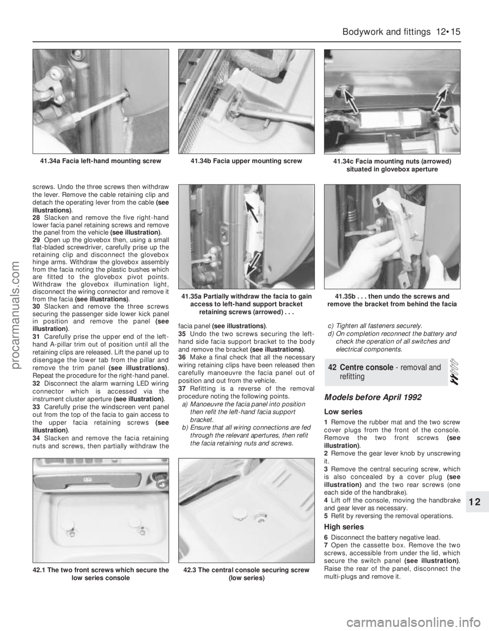
screws. Undo the three screws then withdraw
the lever. Remove the cable retaining clip and
detach the operating lever from the cable (see
illustrations).
28Slacken and remove the five right-hand
lower facia panel retaining screws and remove
the panel from the vehicle (see illustration).
29Open up the glovebox then, using a small
flat-bladed screwdriver, carefully prise up the
retaining clip and disconnect the glovebox
hinge arms. Withdraw the glovebox assembly
from the facia noting the plastic bushes which
are fitted to the glovebox pivot points.
Withdraw the glovebox illumination light,
disconnect the wiring connector and remove it
from the facia (see illustrations).
30Slacken and remove the three screws
securing the passenger side lower kick panel
in position and remove the panel (see
illustration).
31Carefully prise the upper end of the left-
hand A-pillar trim out of position until all the
retaining clips are released. Lift the panel up to
disengage the lower tab from the pillar and
remove the trim panel (see illustrations).
Repeat the procedure for the right-hand panel.
32Disconnect the alarm warning LED wiring
connector which is accessed via the
instrument cluster aperture (see illustration).
33Carefully prise the windscreen vent panel
out from the top of the facia to gain access to
the upper facia retaining screws (see
illustration).
34Slacken and remove the facia retaining
nuts and screws, then partially withdraw thefacia panel (see illustrations).
35Undo the two screws securing the left-
hand side facia support bracket to the body
and remove the bracket (see illustrations).
36Make a final check that all the necessary
wiring retaining clips have been released then
carefully manoeuvre the facia panel out of
position and out from the vehicle.
37Refitting is a reverse of the removal
procedure noting the following points.
a)Manoeuvre the facia panel into position
then refit the left-hand facia support
bracket.
b)Ensure that all wiring connections are fed
through the relevant apertures, then refit
the facia retaining nuts and screws.c)Tighten all fasteners securely.
d)On completion reconnect the battery and
check the operation of all switches and
electrical components.
Models before April 1992
Low series
1Remove the rubber mat and the two screw
cover plugs from the front of the console.
Remove the two front screws (see
illustration).
2Remove the gear lever knob by unscrewing
it.
3Remove the central securing screw, which
is also concealed by a cover plug (see
illustration)and the two rear screws (one
each side of the handbrake).
4Lift off the console, moving the handbrake
and gear lever as necessary.
5Refit by reversing the removal operations.
High series
6Disconnect the battery negative lead.
7Open the cassette box. Remove the two
screws, accessible from under the lid, which
secure the switch panel (see illustration).
Raise the rear of the panel, disconnect the
multi-plugs and remove it.
42Centre console - removal and
refitting
Bodywork and fittings 12•15
12
41.34c Facia mounting nuts (arrowed)
situated in glovebox aperture41.34b Facia upper mounting screw41.34a Facia left-hand mounting screw
41.35a Partially withdraw the facia to gain
access to left-hand support bracket
retaining screws (arrowed) . . .41.35b . . . then undo the screws and
remove the bracket from behind the facia
42.1 The two front screws which secure the
low series console42.3 The central console securing screw
(low series)
procarmanuals.com
Page 173 of 255
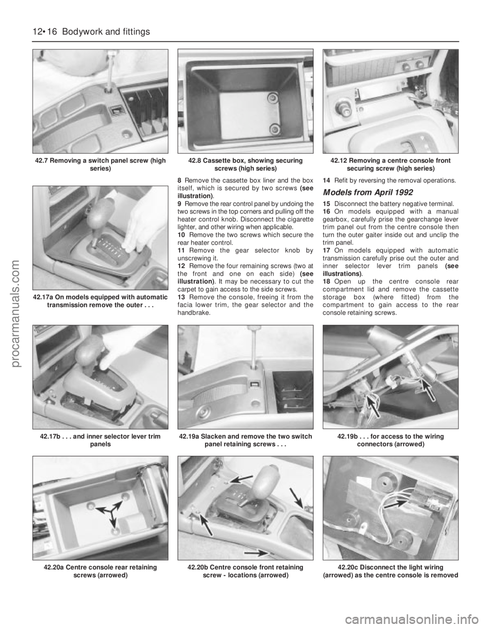
8Remove the cassette box liner and the box
itself, which is secured by two screws (see
illustration).
9Remove the rear control panel by undoing the
two screws in the top corners and pulling off the
heater control knob. Disconnect the cigarette
lighter, and other wiring when applicable.
10Remove the two screws which secure the
rear heater control.
11Remove the gear selector knob by
unscrewing it.
12Remove the four remaining screws (two at
the front and one on each side) (see
illustration). It may be necessary to cut the
carpet to gain access to the side screws.
13Remove the console, freeing it from the
facia lower trim, the gear selector and the
handbrake.14Refit by reversing the removal operations.
Models from April 1992
15Disconnect the battery negative terminal.
16On models equipped with a manual
gearbox, carefully prise the gearchange lever
trim panel out from the centre console then
turn the outer gaiter inside out and unclip the
trim panel.
17On models equipped with automatic
transmission carefully prise out the outer and
inner selector lever trim panels (see
illustrations).
18Open up the centre console rear
compartment lid and remove the cassette
storage box (where fitted) from the
compartment to gain access to the rear
console retaining screws.
12•16Bodywork and fittings
42.7 Removing a switch panel screw (high
series)
42.20a Centre console rear retaining
screws (arrowed)
42.17b . . . and inner selector lever trim
panels
42.17a On models equipped with automatic
transmission remove the outer . . .
42.19a Slacken and remove the two switch
panel retaining screws . . .42.19b . . . for access to the wiring
connectors (arrowed)
42.20b Centre console front retaining
screw - locations (arrowed)42.20c Disconnect the light wiring
(arrowed) as the centre console is removed
42.8 Cassette box, showing securing
screws (high series)42.12 Removing a centre console front
securing screw (high series)
procarmanuals.com
Page 174 of 255
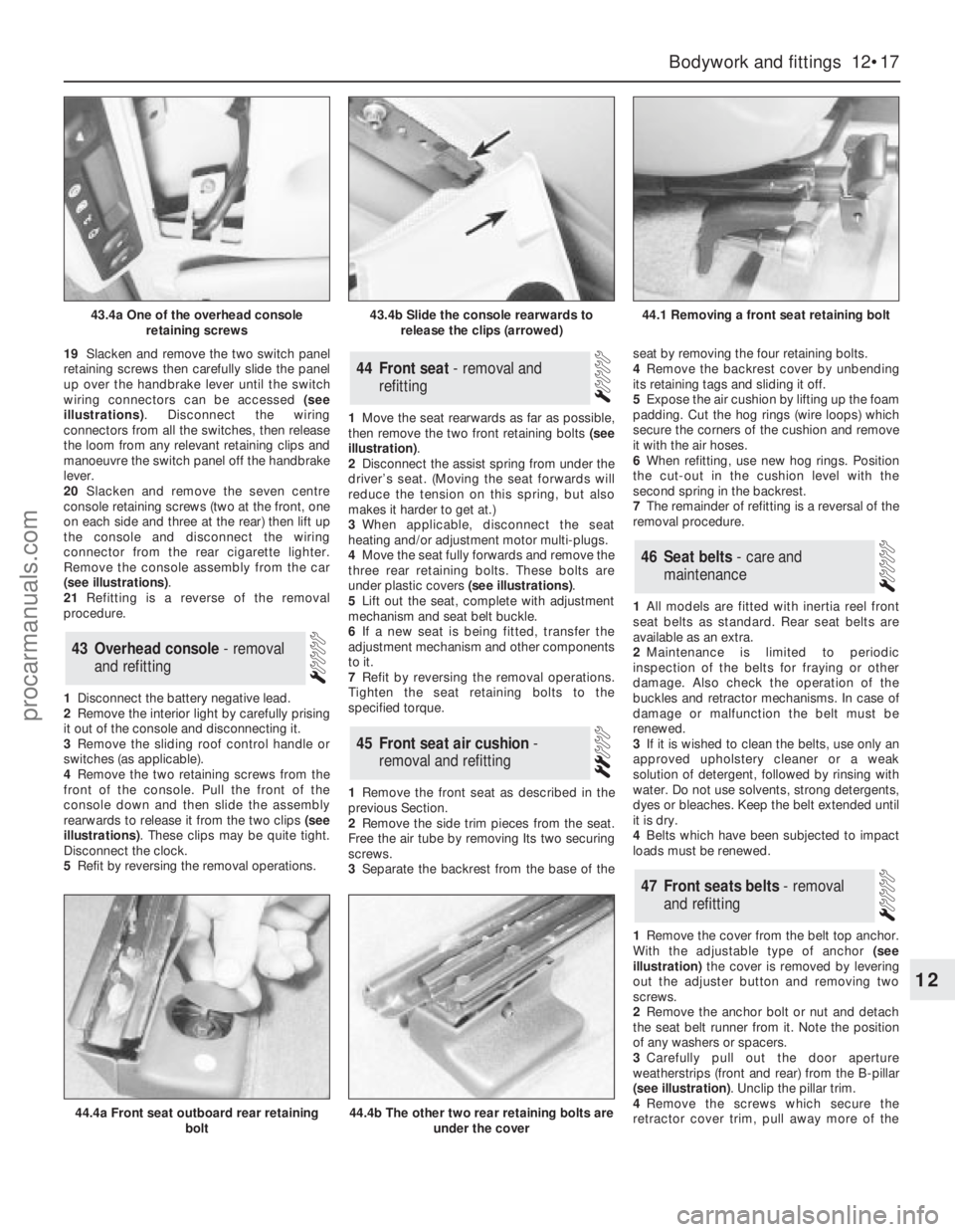
19Slacken and remove the two switch panel
retaining screws then carefully slide the panel
up over the handbrake lever until the switch
wiring connectors can be accessed (see
illustrations). Disconnect the wiring
connectors from all the switches, then release
the loom from any relevant retaining clips and
manoeuvre the switch panel off the handbrake
lever.
20Slacken and remove the seven centre
console retaining screws (two at the front, one
on each side and three at the rear) then lift up
the console and disconnect the wiring
connector from the rear cigarette lighter.
Remove the console assembly from the car
(see illustrations).
21Refitting is a reverse of the removal
procedure.
1Disconnect the battery negative lead.
2Remove the interior light by carefully prising
it out of the console and disconnecting it.
3Remove the sliding roof control handle or
switches (as applicable).
4Remove the two retaining screws from the
front of the console. Pull the front of the
console down and then slide the assembly
rearwards to release it from the two clips (see
illustrations). These clips may be quite tight.
Disconnect the clock.
5Refit by reversing the removal operations.1Move the seat rearwards as far as possible,
then remove the two front retaining bolts (see
illustration).
2Disconnect the assist spring from under the
driver’s seat. (Moving the seat forwards will
reduce the tension on this spring, but also
makes it harder to get at.)
3When applicable, disconnect the seat
heating and/or adjustment motor multi-plugs.
4Move the seat fully forwards and remove the
three rear retaining bolts. These bolts are
under plastic covers (see illustrations).
5Lift out the seat, complete with adjustment
mechanism and seat belt buckle.
6If a new seat is being fitted, transfer the
adjustment mechanism and other components
to it.
7Refit by reversing the removal operations.
Tighten the seat retaining bolts to the
specified torque.
1Remove the front seat as described in the
previous Section.
2Remove the side trim pieces from the seat.
Free the air tube by removing Its two securing
screws.
3Separate the backrest from the base of theseat by removing the four retaining bolts.
4Remove the backrest cover by unbending
its retaining tags and sliding it off.
5Expose the air cushion by lifting up the foam
padding. Cut the hog rings (wire loops) which
secure the corners of the cushion and remove
it with the air hoses.
6When refitting, use new hog rings. Position
the cut-out in the cushion level with the
second spring in the backrest.
7The remainder of refitting is a reversal of the
removal procedure.
1All models are fitted with inertia reel front
seat belts as standard. Rear seat belts are
available as an extra.
2Maintenance is limited to periodic
inspection of the belts for fraying or other
damage. Also check the operation of the
buckles and retractor mechanisms. In case of
damage or malfunction the belt must be
renewed.
3If it is wished to clean the belts, use only an
approved upholstery cleaner or a weak
solution of detergent, followed by rinsing with
water. Do not use solvents, strong detergents,
dyes or bleaches. Keep the belt extended until
it is dry.
4Belts which have been subjected to impact
loads must be renewed.
1Remove the cover from the belt top anchor.
With the adjustable type of anchor(see
illustration)the cover is removed by levering
out the adjuster button and removing two
screws.
2Remove the anchor bolt or nut and detach
the seat belt runner from it. Note the position
of any washers or spacers.
3Carefully pull out the door aperture
weatherstrips (front and rear) from the B-pillar
(see illustration). Unclip the pillar trim.
4Remove the screws which secure the
retractor cover trim, pull away more of the
47Front seats belts - removal
and refitting
46Seat belts - care and
maintenance
45Front seat air cushion -
removal and refitting
44Front seat - removal and
refitting
43Overhead console - removal
and refitting
Bodywork and fittings 12•17
12
43.4a One of the overhead console
retaining screws43.4b Slide the console rearwards to
release the clips (arrowed)44.1 Removing a front seat retaining bolt
44.4a Front seat outboard rear retaining
bolt44.4b The other two rear retaining bolts are
under the cover
procarmanuals.com
Page 175 of 255
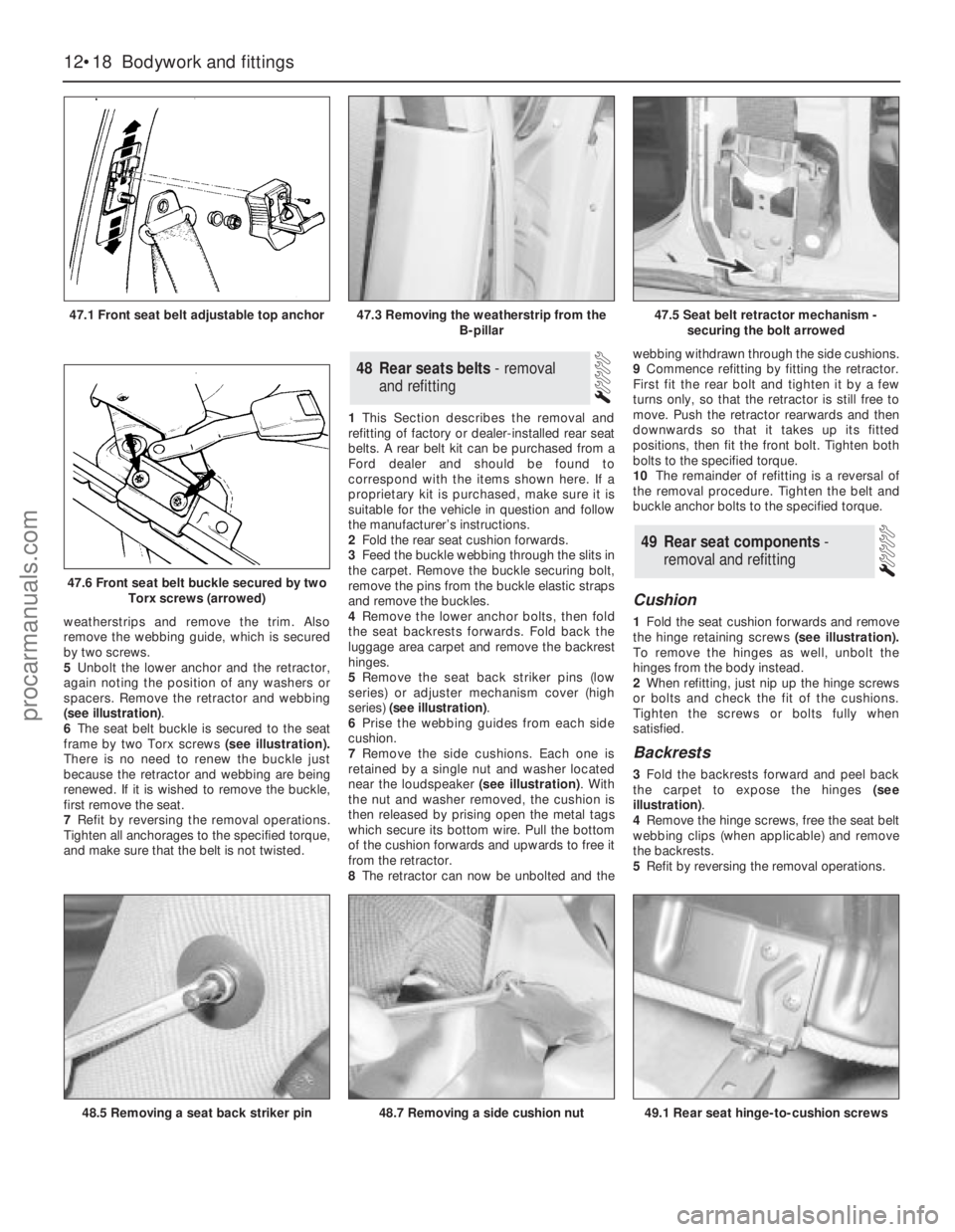
weatherstrips and remove the trim. Also
remove the webbing guide, which is secured
by two screws.
5Unbolt the lower anchor and the retractor,
again noting the position of any washers or
spacers. Remove the retractor and webbing
(see illustration).
6The seat belt buckle is secured to the seat
frame by two Torx screws(see illustration).
There is no need to renew the buckle just
because the retractor and webbing are being
renewed. If it is wished to remove the buckle,
first remove the seat.
7Refit by reversing the removal operations.
Tighten all anchorages to the specified torque,
and make sure that the belt is not twisted.1This Section describes the removal and
refitting of factory or dealer-installed rear seat
belts. A rear belt kit can be purchased from a
Ford dealer and should be found to
correspond with the items shown here. If a
proprietary kit is purchased, make sure it is
suitable for the vehicle in question and follow
the manufacturer’s instructions.
2Fold the rear seat cushion forwards.
3Feed the buckle webbing through the slits in
the carpet. Remove the buckle securing bolt,
remove the pins from the buckle elastic straps
and remove the buckles.
4Remove the lower anchor bolts, then fold
the seat backrests forwards. Fold back the
luggage area carpet and remove the backrest
hinges.
5Remove the seat back striker pins (low
series) or adjuster mechanism cover (high
series) (see illustration).
6Prise the webbing guides from each side
cushion.
7Remove the side cushions. Each one is
retained by a single nut and washer located
near the loudspeaker (see illustration). With
the nut and washer removed, the cushion is
then released by prising open the metal tags
which secure its bottom wire. Pull the bottom
of the cushion forwards and upwards to free it
from the retractor.
8The retractor can now be unbolted and thewebbing withdrawn through the side cushions.
9Commence refitting by fitting the retractor.
First fit the rear bolt and tighten it by a few
turns only, so that the retractor is still free to
move. Push the retractor rearwards and then
downwards so that it takes up its fitted
positions, then fit the front bolt. Tighten both
bolts to the specified torque.
10The remainder of refitting is a reversal of
the removal procedure. Tighten the belt and
buckle anchor bolts to the specified torque.
Cushion
1Fold the seat cushion forwards and remove
the hinge retaining screws (see illustration).
To remove the hinges as well, unbolt the
hinges from the body instead.
2When refitting, just nip up the hinge screws
or bolts and check the fit of the cushions.
Tighten the screws or bolts fully when
satisfied.
Backrests
3Fold the backrests forward and peel back
the carpet to expose the hinges (see
illustration).
4Remove the hinge screws, free the seat belt
webbing clips (when applicable) and remove
the backrests.
5Refit by reversing the removal operations.
49Rear seat components -
removal and refitting
48Rear seats belts - removal
and refitting
12•18Bodywork and fittings
47.1 Front seat belt adjustable top anchor
47.6 Front seat belt buckle secured by two
Torx screws (arrowed)
48.5 Removing a seat back striker pin49.1 Rear seat hinge-to-cushion screws48.7 Removing a side cushion nut
47.3 Removing the weatherstrip from the
B-pillar47.5 Seat belt retractor mechanism -
securing the bolt arrowed
procarmanuals.com
Page 176 of 255
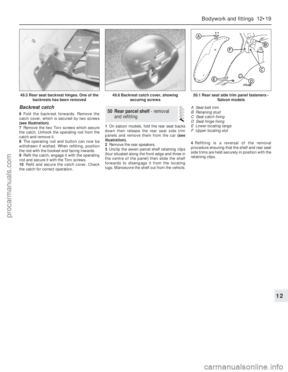
Backrest catch
6Fold the backrest forwards. Remove the
catch cover, which is secured by two screws
(see illustration).
7Remove the two Torx screws which secure
the catch. Unhook the operating rod from the
catch and remove it.
8The operating rod and button can now be
withdrawn if wished. When refitting, position
the rod with the hooked end facing inwards.
9Refit the catch, engage it with the operating
rod and secure it with the Torx screws.
10Refit and secure the catch cover. Check
the catch for correct operation.1On saloon models, fold the rear seat backs
down then release the rear seat side trim
panels and remove them from the car (see
illustration).
2Remove the rear speakers.
3Unclip the seven parcel shelf retaining clips
(four situated along the front edge and three in
the centre of the panel) then slide the shelf
forwards to disengage it from the locating
lugs. Manoeuvre the shelf out from the vehicle.4Refitting is a reversal of the removal
procedure ensuring that the shelf and rear seat
side trims are held securely in position with the
retaining clips.50Rear parcel shelf - removal
and refitting
Bodywork and fittings 12•19
12
49.3 Rear seat backrest hinges. One of the
backrests has been removed49.6 Backrest catch cover, showing
securing screws50.1 Rear seat side trim panel fasteners -
Saloon models
A Seat belt trim
B Retaining stud
C Seat catch fixing
D Seat hinge fixing
E Lower locating tangs
F Upper locating slot
procarmanuals.com
Page 177 of 255
12•20Notes
procarmanuals.com
Page 178 of 255
Chapter 13
Body electrical system
Anti-theft alarm system components - removal and refitting . . . . . .36
Auxiliary warning system components - testing, removal and
refitting . . . . . . . . . . . . . . . . . . . . . . . . . . . . . . . . . . . . . . . . . . . . .27
Central locking motor - removal and refitting . . . . . . . . . . . . . . . . . .17
Cigarette lighter - removal and refitting . . . . . . . . . . . . . . . . . . . . . .10
Clock - removal and refitting . . . . . . . . . . . . . . . . . . . . . . . . . . . . . . .9
Electrical fault-finding - general information . . . . . . . . . . . . . . . . . . .2
Exterior lights - bulb renewal . . . . . . . . . . . . . . . . . . . . . . . . . . . . . . .3
Exterior light units - removal and refitting . . . . . . . . . . . . . . . . . . . . .4
Fuel computer components - removal and refitting . . . . . . . . . . . . .26
Fuses, relays and control units - removal and refitting . . . . . . . . . .16
General information . . . . . . . . . . . . . . . . . . . . . . . . . . . . . . . . . . . . . .1
Headlight beam alignment . . . . . . . . . . . . . . . . . . . . . . . . . . . . . . . . .5
Heater blower motor - removal and refitting . . . . . . . . . . . . . . . . . .29
Horn - removal and refitting . . . . . . . . . . . . . . . . . . . . . . . . . . . . . . .11
Horn switch plate, slip rings and brushes - removal and refitting . .12
Ignition/starter switch - removal and refitting . . . . . . . . . . . . . . . . . .14
Instrument cluster - dismantling and reassembly . . . . . . . . . . . . . . .8
Instrument cluster - removal and refitting . . . . . . . . . . . . . . . . . . . . .7
Interior lights - bulb renewal . . . . . . . . . . . . . . . . . . . . . . . . . . . . . . . .6Joystick fader control - removal and refitting . . . . . . . . . . . . . . . . . .33
Loudspeakers (original equipment) - removal and refitting . . . . . . .31
Radio aerial pre-amplifier (original equipment) - removal and
refitting . . . . . . . . . . . . . . . . . . . . . . . . . . . . . . . . . . . . . . . . . . . . .32
Radio or radio/cassette player (original equipment) - removal and
refitting . . . . . . . . . . . . . . . . . . . . . . . . . . . . . . . . . . . . . . . . . . . . .30
Rear entertainment console - removal and refitting . . . . . . . . . . . . .34
Rear headphone relay - removal and refitting . . . . . . . . . . . . . . . . .35
Rear window wiper motor - removal and refitting . . . . . . . . . . . . . .24
Seat adjusting motors - removal and refitting . . . . . . . . . . . . . . . . .19
Seat heating elements - removal and refitting . . . . . . . . . . . . . . . . .13
Sliding roof motor - removal and refitting . . . . . . . . . . . . . . . . . . . .20
Speed control system components - removal and refitting . . . . . . .28
Speedometer sender unit - removal and refitting . . . . . . . . . . . . . . .21
Switches - removal and refitting . . . . . . . . . . . . . . . . . . . . . . . . . . . .15
Window operating motor - removal and refitting . . . . . . . . . . . . . . .18
Windscreen, rear window and headlight washer components -
removal and refitting . . . . . . . . . . . . . . . . . . . . . . . . . . . . . . . . . . .25
Windscreen wiper motor and linkage - removal and refitting . . . . .23
Wiper arms and blades - removal and refitting . . . . . . . . . . . . . . . .22
General
System type . . . . . . . . . . . . . . . . . . . . . . . . . . . . . . . . . . . . . . . . . . . . . . 12 volt, negative earth
Light bulbs (typical)Fitting Wattage
Headlights . . . . . . . . . . . . . . . . . . . . . . . . . . . . . . . . . . . . . . . . . . . . . . . . H4 60/55
Auxiliary driving lights and front foglights . . . . . . . . . . . . . . . . . . . . . . . . H3 55
Side/parking lights . . . . . . . . . . . . . . . . . . . . . . . . . . . . . . . . . . . . . . . . . Glass base 5
Direction indicators, reversing light and rear foglight . . . . . . . . . . . . . . . Bayonet 21
Stop and tail lights . . . . . . . . . . . . . . . . . . . . . . . . . . . . . . . . . . . . . . . . . Bayonet 21/5
Door open/kerb illumination lights, luggage area light . . . . . . . . . . . . . . Bayonet 5
Number plate lights, reading light and footwell lights . . . . . . . . . . . . . . Glass base 5
Engine bay light . . . . . . . . . . . . . . . . . . . . . . . . . . . . . . . . . . . . . . . . . . . Bayonet 10
Interior lights . . . . . . . . . . . . . . . . . . . . . . . . . . . . . . . . . . . . . . . . . . . . . . Festoon 10
Vanity mirror light . . . . . . . . . . . . . . . . . . . . . . . . . . . . . . . . . . . . . . . . . . Festoon 3
Glovebox light . . . . . . . . . . . . . . . . . . . . . . . . . . . . . . . . . . . . . . . . . . . . . Glass base 3
Ashtray light . . . . . . . . . . . . . . . . . . . . . . . . . . . . . . . . . . . . . . . . . . . . . . Glass base 1.2
Instrument illumination, pilot and warning lights . . . . . . . . . . . . . . . . . . Glass base 1.2/2.5
Heater control light . . . . . . . . . . . . . . . . . . . . . . . . . . . . . . . . . . . . . . . . . Glass base 1
Automatic transmission selector light and clock light . . . . . . . . . . . . . . Bayonet 1.4
Fuses and circuit breakers- main fuse box
Fuse No Rating (A) Circuit(s) protected
1 20 . . . . . . . . . . . . . . . . . . . . . . . . . . . . . . . . . . . . . . . . . . . . . . . LH main beam, LH auxiliary driving light
2 20 . . . . . . . . . . . . . . . . . . . . . . . . . . . . . . . . . . . . . . . . . . . . . . . RH main beam, LH auxiliary driving light
3 10 . . . . . . . . . . . . . . . . . . . . . . . . . . . . . . . . . . . . . . . . . . . . . . . LH dipped beam
4 10 . . . . . . . . . . . . . . . . . . . . . . . . . . . . . . . . . . . . . . . . . . . . . . . RH dipped beam
5 10 . . . . . . . . . . . . . . . . . . . . . . . . . . . . . . . . . . . . . . . . . . . . . . . LH side and tail lights
6 10 . . . . . . . . . . . . . . . . . . . . . . . . . . . . . . . . . . . . . . . . . . . . . . . RH side and tail lights
13•1
Easy,suitable for
novice with little
experienceFairly easy,suitable
for beginner with
some experienceFairly difficult,
suitable for competent
DIY mechanicDifficult,suitable for
experienced DIY
mechanicVery difficult,
suitable for expert
DIY or professional
Degrees of difficulty
Specifications Contents
13
procarmanuals.com
Page 179 of 255
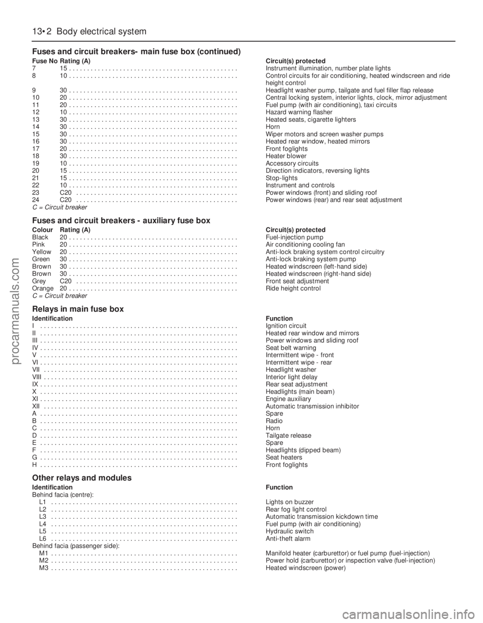
13•2Body electrical system
Fuses and circuit breakers- main fuse box (continued)
Fuse NoRating (A)Circuit(s) protected
715 . . . . . . . . . . . . . . . . . . . . . . . . . . . . . . . . . . . . . . . . . . . . . . .Instrument illumination, number plate lights
810 . . . . . . . . . . . . . . . . . . . . . . . . . . . . . . . . . . . . . . . . . . . . . . .Control circuits for air conditioning, heated windscreen and ride
height control
930 . . . . . . . . . . . . . . . . . . . . . . . . . . . . . . . . . . . . . . . . . . . . . . .Headlight washer pump, tailgate and fuel filler flap release
1020 . . . . . . . . . . . . . . . . . . . . . . . . . . . . . . . . . . . . . . . . . . . . . . .Central locking system, interior lights, clock, mirror adjustment
1120 . . . . . . . . . . . . . . . . . . . . . . . . . . . . . . . . . . . . . . . . . . . . . . .Fuel pump (with air conditioning), taxi circuits
1210 . . . . . . . . . . . . . . . . . . . . . . . . . . . . . . . . . . . . . . . . . . . . . . .Hazard warning flasher
1330 . . . . . . . . . . . . . . . . . . . . . . . . . . . . . . . . . . . . . . . . . . . . . . .Heated seats, cigarette lighters
1430 . . . . . . . . . . . . . . . . . . . . . . . . . . . . . . . . . . . . . . . . . . . . . . .Horn
1530 . . . . . . . . . . . . . . . . . . . . . . . . . . . . . . . . . . . . . . . . . . . . . . .Wiper motors and screen washer pumps
1630 . . . . . . . . . . . . . . . . . . . . . . . . . . . . . . . . . . . . . . . . . . . . . . .Heated rear window, heated mirrors
1720 . . . . . . . . . . . . . . . . . . . . . . . . . . . . . . . . . . . . . . . . . . . . . . .Front foglights
1830 . . . . . . . . . . . . . . . . . . . . . . . . . . . . . . . . . . . . . . . . . . . . . . .Heater blower
1910 . . . . . . . . . . . . . . . . . . . . . . . . . . . . . . . . . . . . . . . . . . . . . . .Accessory circuits
2015 . . . . . . . . . . . . . . . . . . . . . . . . . . . . . . . . . . . . . . . . . . . . . . .Direction indicators, reversing lights
2115 . . . . . . . . . . . . . . . . . . . . . . . . . . . . . . . . . . . . . . . . . . . . . . .Stop-lights
2210 . . . . . . . . . . . . . . . . . . . . . . . . . . . . . . . . . . . . . . . . . . . . . . .Instrument and controls
23C20 . . . . . . . . . . . . . . . . . . . . . . . . . . . . . . . . . . . . . . . . . . . . .Power windows (front) and sliding roof
24C20 . . . . . . . . . . . . . . . . . . . . . . . . . . . . . . . . . . . . . . . . . . . . .Power windows (rear) and rear seat adjustment
C = Circuit breaker
Fuses and circuit breakers - auxiliary fuse box
Colour Rating (A)Circuit(s) protected
Black20 . . . . . . . . . . . . . . . . . . . . . . . . . . . . . . . . . . . . . . . . . . . . . . .Fuel-injection pump
Pink20 . . . . . . . . . . . . . . . . . . . . . . . . . . . . . . . . . . . . . . . . . . . . . . .Air conditioning cooling fan
Yellow20 . . . . . . . . . . . . . . . . . . . . . . . . . . . . . . . . . . . . . . . . . . . . . . .Anti-lock braking system control circuitry
Green30 . . . . . . . . . . . . . . . . . . . . . . . . . . . . . . . . . . . . . . . . . . . . . . .Anti-lock braking system pump
Brown30 . . . . . . . . . . . . . . . . . . . . . . . . . . . . . . . . . . . . . . . . . . . . . . .Heated windscreen (left-hand side)
Brown30 . . . . . . . . . . . . . . . . . . . . . . . . . . . . . . . . . . . . . . . . . . . . . . .Heated windscreen (right-hand side)
GreyC20 . . . . . . . . . . . . . . . . . . . . . . . . . . . . . . . . . . . . . . . . . . . . .Front seat adjustment
Orange20 . . . . . . . . . . . . . . . . . . . . . . . . . . . . . . . . . . . . . . . . . . . . . . .Ride height control
C = Circuit breaker
Relays in main fuse box
IdentificationFunction
I . . . . . . . . . . . . . . . . . . . . . . . . . . . . . . . . . . . . . . . . . . . . . . . . . . . . . . .Ignition circuit
II . . . . . . . . . . . . . . . . . . . . . . . . . . . . . . . . . . . . . . . . . . . . . . . . . . . . . . .Heated rear window and mirrors
III . . . . . . . . . . . . . . . . . . . . . . . . . . . . . . . . . . . . . . . . . . . . . . . . . . . . . . .Power windows and sliding roof
IV . . . . . . . . . . . . . . . . . . . . . . . . . . . . . . . . . . . . . . . . . . . . . . . . . . . . . . .Seat belt warning
V . . . . . . . . . . . . . . . . . . . . . . . . . . . . . . . . . . . . . . . . . . . . . . . . . . . . . . .Intermittent wipe - front
VI . . . . . . . . . . . . . . . . . . . . . . . . . . . . . . . . . . . . . . . . . . . . . . . . . . . . . . .Intermittent wipe - rear
VII . . . . . . . . . . . . . . . . . . . . . . . . . . . . . . . . . . . . . . . . . . . . . . . . . . . . . .Headlight washer
VIII . . . . . . . . . . . . . . . . . . . . . . . . . . . . . . . . . . . . . . . . . . . . . . . . . . . . . .Interior light delay
IX . . . . . . . . . . . . . . . . . . . . . . . . . . . . . . . . . . . . . . . . . . . . . . . . . . . . . . .Rear seat adjustment
X . . . . . . . . . . . . . . . . . . . . . . . . . . . . . . . . . . . . . . . . . . . . . . . . . . . . . . .Headlights (main beam)
XI . . . . . . . . . . . . . . . . . . . . . . . . . . . . . . . . . . . . . . . . . . . . . . . . . . . . . . .Engine auxiliary
XII . . . . . . . . . . . . . . . . . . . . . . . . . . . . . . . . . . . . . . . . . . . . . . . . . . . . . .Automatic transmission inhibitor
A . . . . . . . . . . . . . . . . . . . . . . . . . . . . . . . . . . . . . . . . . . . . . . . . . . . . . . .Spare
B . . . . . . . . . . . . . . . . . . . . . . . . . . . . . . . . . . . . . . . . . . . . . . . . . . . . . . .Radio
C . . . . . . . . . . . . . . . . . . . . . . . . . . . . . . . . . . . . . . . . . . . . . . . . . . . . . . .Horn
D . . . . . . . . . . . . . . . . . . . . . . . . . . . . . . . . . . . . . . . . . . . . . . . . . . . . . . .Tailgate release
E . . . . . . . . . . . . . . . . . . . . . . . . . . . . . . . . . . . . . . . . . . . . . . . . . . . . . . .Spare
F . . . . . . . . . . . . . . . . . . . . . . . . . . . . . . . . . . . . . . . . . . . . . . . . . . . . . . .Headlights (dipped beam)
G . . . . . . . . . . . . . . . . . . . . . . . . . . . . . . . . . . . . . . . . . . . . . . . . . . . . . . .Seat heaters
H . . . . . . . . . . . . . . . . . . . . . . . . . . . . . . . . . . . . . . . . . . . . . . . . . . . . . . .Front foglights
Other relays and modules
IdentificationFunction
Behind facia (centre):
L1 . . . . . . . . . . . . . . . . . . . . . . . . . . . . . . . . . . . . . . . . . . . . . . . . . . . .Lights on buzzer
L2 . . . . . . . . . . . . . . . . . . . . . . . . . . . . . . . . . . . . . . . . . . . . . . . . . . . .Rear fog light control
L3 . . . . . . . . . . . . . . . . . . . . . . . . . . . . . . . . . . . . . . . . . . . . . . . . . . . .Automatic transmission kickdown time
L4 . . . . . . . . . . . . . . . . . . . . . . . . . . . . . . . . . . . . . . . . . . . . . . . . . . . .Fuel pump (with air conditioning)
L5 . . . . . . . . . . . . . . . . . . . . . . . . . . . . . . . . . . . . . . . . . . . . . . . . . . . .Hydraulic switch
L6 . . . . . . . . . . . . . . . . . . . . . . . . . . . . . . . . . . . . . . . . . . . . . . . . . . . .Anti-theft alarm
Behind facia (passenger side):
M1 . . . . . . . . . . . . . . . . . . . . . . . . . . . . . . . . . . . . . . . . . . . . . . . . . . . .Manifold heater (carburettor) or fuel pump (fuel-injection)
M2 . . . . . . . . . . . . . . . . . . . . . . . . . . . . . . . . . . . . . . . . . . . . . . . . . . . .Power hold (carburettor) or inspection valve (fuel-injection)
M3 . . . . . . . . . . . . . . . . . . . . . . . . . . . . . . . . . . . . . . . . . . . . . . . . . . . .Heated windscreen (power)
procarmanuals.com
Page 180 of 255
The electrical system is a 12 volt, negative
earth type. Electricity is generated by an
alternator, belt-driven from the crankshaft pulley.
A lead-acid battery provides a reserve of power
for starting and when the demands of the system
temporarily exceed the alternator output.
The battery negative terminal is connected
to “earth” - vehicle metal - and most electrical
system components are wired so that they
only receive a positive feed, the current
returning via vehicle metal. This means that
the component mounting forms part of the
circuit. Loose or corroded mountings can
therefore cause apparent electrical faults.
Many semiconductor devices are used in
the electrical system, both in the “black
boxes” which control vehicle functions and in
other components. Semiconductors are very
sensitive to excessive (or wrong polarity)
voltage, and to extremes of heat. Observe the
appropriate precautions to avoid damage.
Although some repair procedures are given
in this Chapter, sometimes renewal of a well-
used item will prove more satisfactory. The
reader whose interests extend beyond
component renewal should obtain a copy of
the “Automobile Electrical Manual”, available
from the publishers of this book.
Before starting work on the electrical
system, read the precautions listed in “Safety
first!” at the beginning of the manual.
Note:Refer to the precautions given in “Safety
first!” and in Section 1 of this Chapter before
starting work. The following tests relate to testing
of the main electrical circuits, and should not be
used to test delicate electronic circuits (such as
anti-lock braking systems), particularly where an
electronic control unit (ECU) is involved.
General
1A typical electrical circuit consists of an
electrical component, any switches, relays,
motors, fuses, fusible links or circuit breakers
related to that component, and the wiring and
connectors which link the component to both
the battery and the chassis. To help to
pinpoint a problem in an electrical circuit,
wiring diagrams are included at the end of this
Chapter.
2Before attempting to diagnose an electrical
fault, first study the appropriate wiring
diagram, to obtain a more complete
understanding of the components included in
the particular circuit concerned. The possible
sources of a fault can be narrowed down by
noting whether other components related to
the circuit are operating properly. If several
components or circuits fail at one time, the
problem is likely to be related to a shared fuse
or earth connection.
3Electrical problems usually stem from
simple causes, such as loose or corroded
connections, a faulty earth connection, a
blown fuse, a melted fusible link, or a faulty
relay. Visually inspect the condition of all
fuses, wires and connections in a problem
circuit before testing the components. Use the
wiring diagrams to determine which terminal
connections will need to be checked in order
to pinpoint the trouble-spot.
4The basic tools required for electrical fault-
finding include: a circuit tester or voltmeter (a
12-volt bulb with a set of test leads can also
be used for certain tests), a self-powered test
light (sometimes known as a continuity tester),
an ohmmeter (to measure resistance), a
battery and set of test leads, and a jumper
wire, preferably with a circuit breaker or fuse
incorporated, which can be used to bypass
suspect wires or electrical components.
Before attempting to locate a problem with
test instruments, use the wiring diagram to
determine where to make the connections.
5To find the source of an intermittent wiring
fault (usually due to a poor or dirty connection,
or damaged wiring insulation), an integrity testcan be performed on the wiring, which
involves moving the wiring by hand, to see if
the fault occurs as the wiring is moved. It
should be possible to narrow down the source
of the fault to a particular section of wiring.
This method of testing can be used in
conjunction with any of the tests described in
the following sub-Sections.
6Apart from problems due to poor
connections, two basic types of fault can
occur in an electrical circuit - open-circuit or
short-circuit.
7Open-circuit faults are caused by a break
somewhere in the circuit, which prevents
current from flowing. An open-circuit fault will
prevent a component from working, but will
not cause the relevant circuit fuse to blow.
8Short-circuit faults are caused by a “short”
somewhere in the circuit, which allows the
current flowing in the circuit to “escape” along
an alternative route, usually to earth. Short-
circuit faults are normally caused by a
breakdown in wiring insulation, which allows a
feed wire to touch either another wire, or an
earthed component such as the bodyshell. A
short-circuit fault will normally cause the
relevant circuit fuse to blow. Note: A short-
circuit that occurs in the wiring between a
circuit’s battery supply and its fuse will not
cause the fuse in that particular circuit to blow.
This part of the circuit is unprotected - bear
this in mind when fault-finding on the vehicle’s
electrical system.
Finding an open-circuit
9To check for an open-circuit, connect one
lead of a circuit tester or voltmeter to either the
negative battery terminal or a known good earth.
10Connect the other lead to a connector in
the circuit being tested, preferably nearest to
the battery or fuse.
11Switch on the circuit, bearing in mind that
some circuits are live only when the ignition
switch is moved to a particular position.
12If voltage is present (indicated either by
the tester bulb lighting or a voltmeter reading,
as applicable), this means that the section of
2Electrical fault-finding - general
information
1General information
Body electrical system 13•3
13
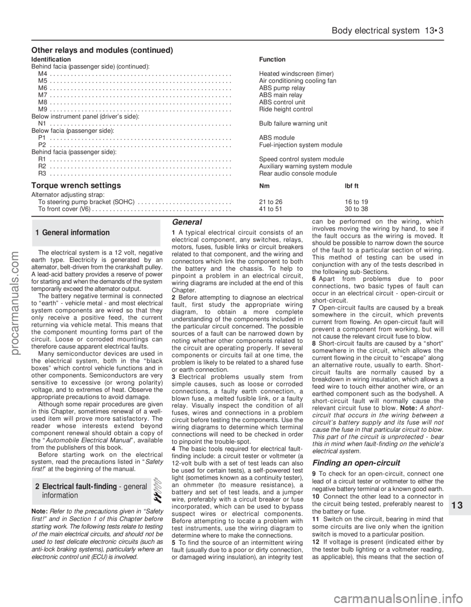
Other relays and modules (continued)
IdentificationFunction
Behind facia (passenger side) (continued):
M4 . . . . . . . . . . . . . . . . . . . . . . . . . . . . . . . . . . . . . . . . . . . . . . . . . . . .Heated windscreen (timer)
M5 . . . . . . . . . . . . . . . . . . . . . . . . . . . . . . . . . . . . . . . . . . . . . . . . . . . .Air conditioning cooling fan
M6 . . . . . . . . . . . . . . . . . . . . . . . . . . . . . . . . . . . . . . . . . . . . . . . . . . . .ABS pump relay
M7 . . . . . . . . . . . . . . . . . . . . . . . . . . . . . . . . . . . . . . . . . . . . . . . . . . . .ABS main relay
M8 . . . . . . . . . . . . . . . . . . . . . . . . . . . . . . . . . . . . . . . . . . . . . . . . . . . .ABS control unit
M9 . . . . . . . . . . . . . . . . . . . . . . . . . . . . . . . . . . . . . . . . . . . . . . . . . . . .Ride height control
Below instrument panel (driver’s side):
N1 . . . . . . . . . . . . . . . . . . . . . . . . . . . . . . . . . . . . . . . . . . . . . . . . . . . .Bulb failure warning unit
Below facia (passenger side):
P1 . . . . . . . . . . . . . . . . . . . . . . . . . . . . . . . . . . . . . . . . . . . . . . . . . . . .ABS module
P2 . . . . . . . . . . . . . . . . . . . . . . . . . . . . . . . . . . . . . . . . . . . . . . . . . . . .Fuel-injection system module
Behind facia (passenger side):
R1 . . . . . . . . . . . . . . . . . . . . . . . . . . . . . . . . . . . . . . . . . . . . . . . . . . . .Speed control system module
R2 . . . . . . . . . . . . . . . . . . . . . . . . . . . . . . . . . . . . . . . . . . . . . . . . . . . .Auxiliary warning system module
R3 . . . . . . . . . . . . . . . . . . . . . . . . . . . . . . . . . . . . . . . . . . . . . . . . . . . .Rear audio console module
Torque wrench settingsNmlbf ft
Alternator adjusting strap:
To steering pump bracket (SOHC) . . . . . . . . . . . . . . . . . . . . . . . . . . .21 to 2616 to 19
To front cover (V6) . . . . . . . . . . . . . . . . . . . . . . . . . . . . . . . . . . . . . . . .41 to 5130 to 38
procarmanuals.com