FORD KUGA 2011 1.G Workshop Manual
Manufacturer: FORD, Model Year: 2011, Model line: KUGA, Model: FORD KUGA 2011 1.GPages: 2057
Page 1501 of 2057
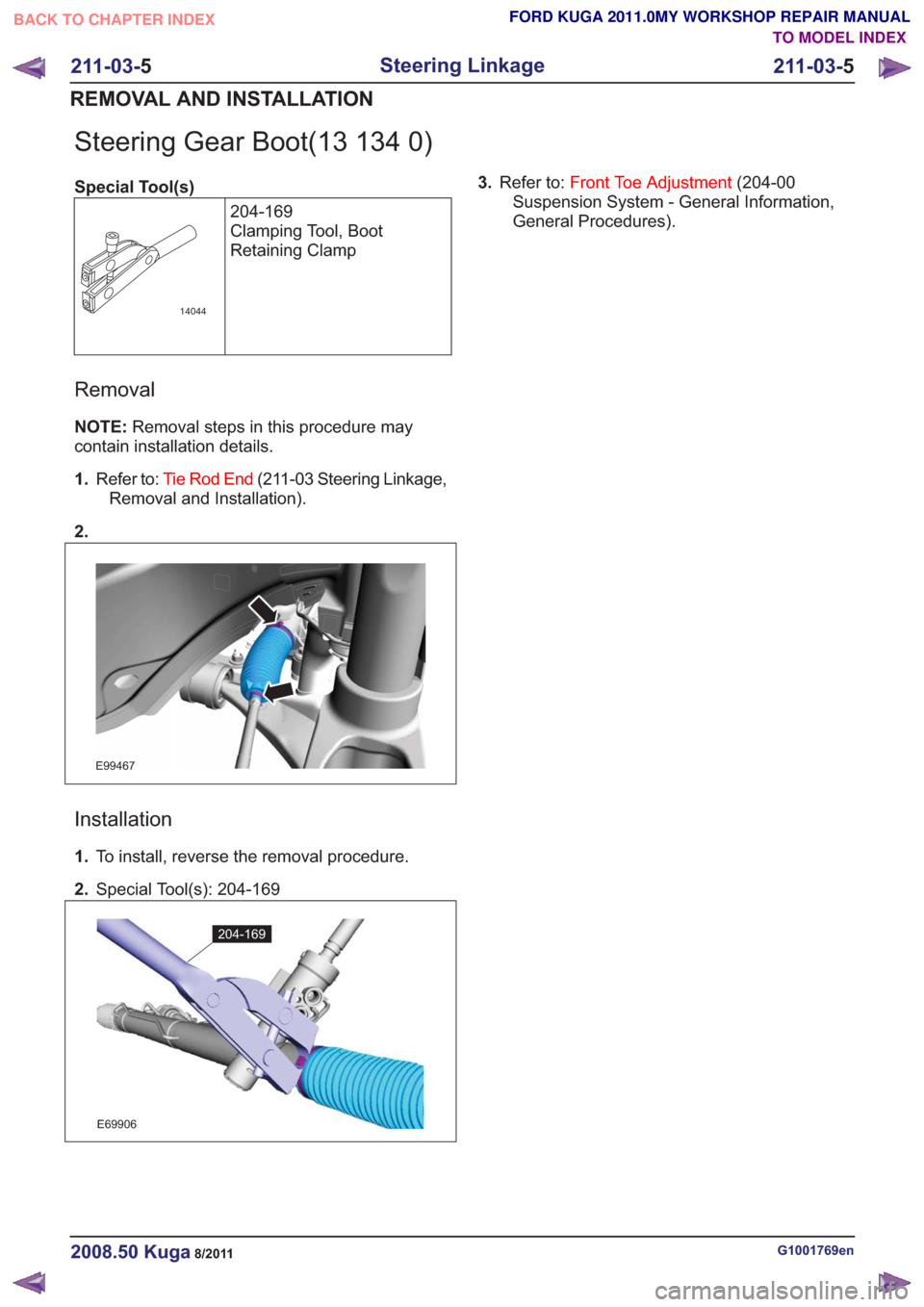
Steering Gear Boot(13 134 0)
Special Tool(s)204-169
Clamping Tool, Boot
Retaining Clamp
14044
Removal
NOTE:Removal steps in this procedure may
contain installation details.
1. Refer to: Tie Rod End (211-03 Steering Linkage,
Removal and Installation).
2.
E99467
Installation
1. To install, reverse the removal procedure.
2. Special Tool(s): 204-169
E69906
204-169
3.Refer to: Front Toe Adjustment (204-00
Suspension System - General Information,
General Procedures).
G1001769en2008.50 Kuga8/2011
211-03- 5
Steering Linkage
211-03- 5
REMOVAL AND INSTALLATION
TO MODEL INDEX
BACK TO CHAPTER INDEX
FORD KUGA 2011.0MY WORKSHOP REPAIR MANUAL
Page 1502 of 2057
SECTION 211-04 Steering Column
VEHICLE APPLICATION:2008.50 Kuga
PA G E
CONTENTS
DESCRIPTION AND OPERATION
211-04-2
Steering Column (Overview) ........................................................................\
......................
211-04-2
General overview ........................................................................\
........................................
211-04-3
Steering wheel ........................................................................\
............................................
211-04-3
Extension, steering shaft ........................................................................\
............................
211-04-3
Steering Column ........................................................................\
.........................................
REMOVAL AND INSTALLATION 211-04-4
(13 524 0)
Steering Wheel ........................................................................\
.......................
211-04-5
(13 542 0)
Steering Column ........................................................................\
.....................
211-04-7
Steering Column Shaft ........................................................................\
................................
211-04-1
Steering Column
211-04- 1
.
TO MODEL INDEX
BACK TO CHAPTER INDEX
FORD KUGA 2011.0MY WORKSHOP REPAIR MANUAL
Page 1503 of 2057
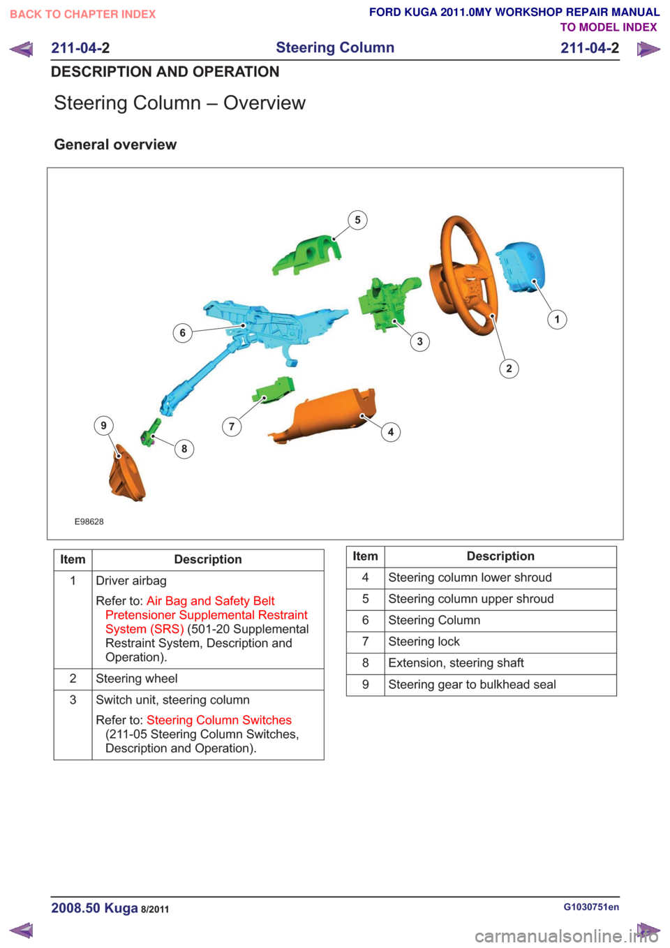
Steering Column – Overview
General overview
E98628
1
2
3
4
5
6
7
8
9
Description
Item
Driver airbag
Refer to: Air Bag and Safety Belt
Pretensioner Supplemental Restraint
System (SRS) (501-20 Supplemental
Restraint System, Description and
Operation).
1
Steering wheel
2
Switch unit, steering column
Refer to: Steering Column Switches
(211-05 Steering Column Switches,
Description and Operation).
3Description
Item
Steering column lower shroud
4
Steering column upper shroud
5
Steering Column
6
Steering lock
7
Extension, steering shaft
8
Steering gear to bulkhead seal
9
G1030751en2008.50 Kuga8/2011
211-04- 2
Steering Column
211-04- 2
DESCRIPTION AND OPERATION
TO MODEL INDEX
BACK TO CHAPTER INDEX
FORD KUGA 2011.0MY WORKSHOP REPAIR MANUAL
Page 1504 of 2057
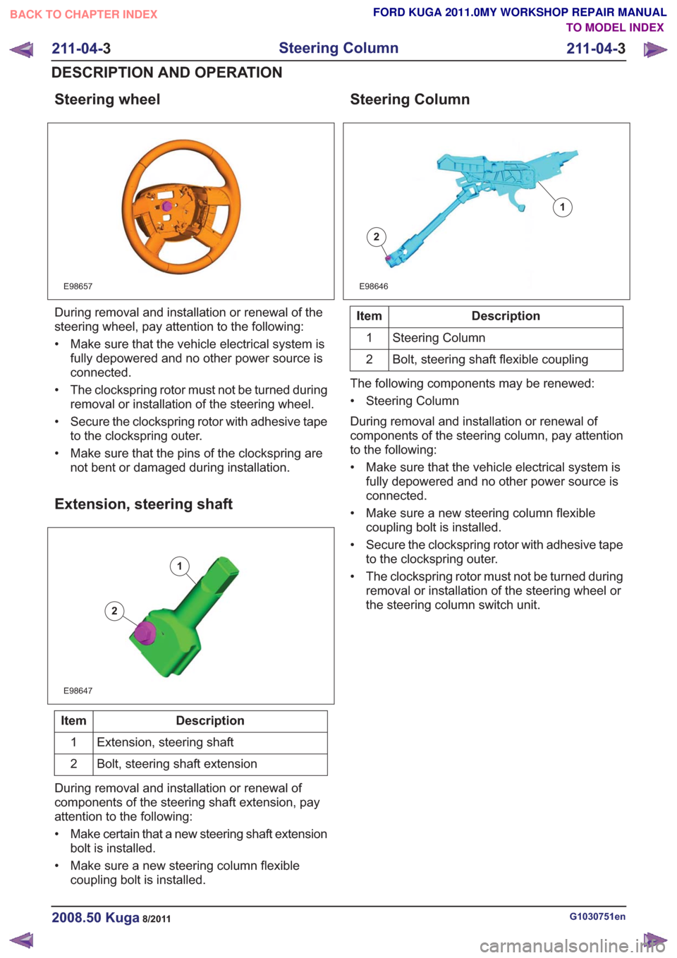
Steering wheel
E98657
During removal and installation or renewal of the
steering wheel, pay attention to the following:
• Make sure that the vehicle electrical system isfully depowered and no other power source is
connected.
• The clockspring rotor must not be turned during removal or installation of the steering wheel.
• Secure the clockspring rotor with adhesive tape to the clockspring outer.
• Make sure that the pins of the clockspring are not bent or damaged during installation.
Extension, steering shaft
E98647
1
2
Description
Item
Extension, steering shaft
1
Bolt, steering shaft extension
2
During removal and installation or renewal of
components of the steering shaft extension, pay
attention to the following:
• Make certain that a new steering shaft extension bolt is installed.
• Make sure a new steering column flexible coupling bolt is installed.
Steering Column
E98646
1
2
Description
Item
Steering Column
1
Bolt, steering shaft flexible coupling
2
The following components may be renewed:
• Steering Column
During removal and installation or renewal of
components of the steering column, pay attention
to the following:
• Make sure that the vehicle electrical system is fully depowered and no other power source is
connected.
• Make sure a new steering column flexible coupling bolt is installed.
• Secure the clockspring rotor with adhesive tape to the clockspring outer.
• The clockspring rotor must not be turned during removal or installation of the steering wheel or
the steering column switch unit.
G1030751en2008.50 Kuga8/2011
211-04- 3
Steering Column
211-04- 3
DESCRIPTION AND OPERATION
TO MODEL INDEX
BACK TO CHAPTER INDEX
FORD KUGA 2011.0MY WORKSHOP REPAIR MANUAL
Page 1505 of 2057
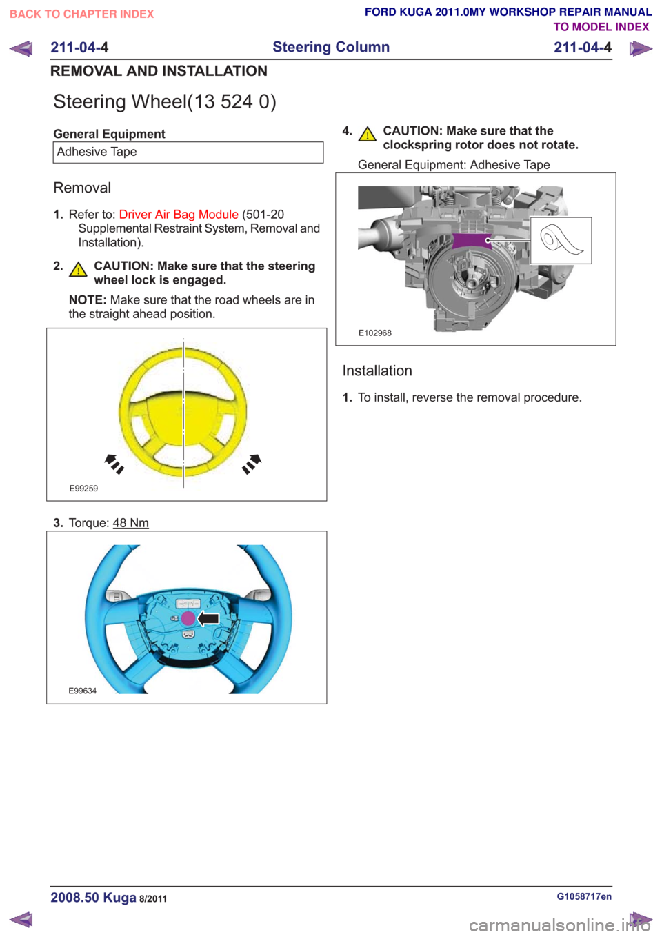
Steering Wheel(13 524 0)
General EquipmentAdhesive Tape
Removal
1. Refer to: Driver Air Bag Module (501-20
Supplemental Restraint System, Removal and
Installation).
2. CAUTION: Make sure that the steering wheel lock is engaged.
NOTE: Make sure that the road wheels are in
the straight ahead position.
E99259
3. Torque: 48Nm
E99634
4. CAUTION: Make sure that the
clockspring rotor does not rotate.
General Equipment: Adhesive Tape
E102968
Installation
1.To install, reverse the removal procedure.
G1058717en2008.50 Kuga8/2011
211-04- 4
Steering Column
211-04- 4
REMOVAL AND INSTALLATION
TO MODEL INDEX
BACK TO CHAPTER INDEX
FORD KUGA 2011.0MY WORKSHOP REPAIR MANUAL
Page 1506 of 2057
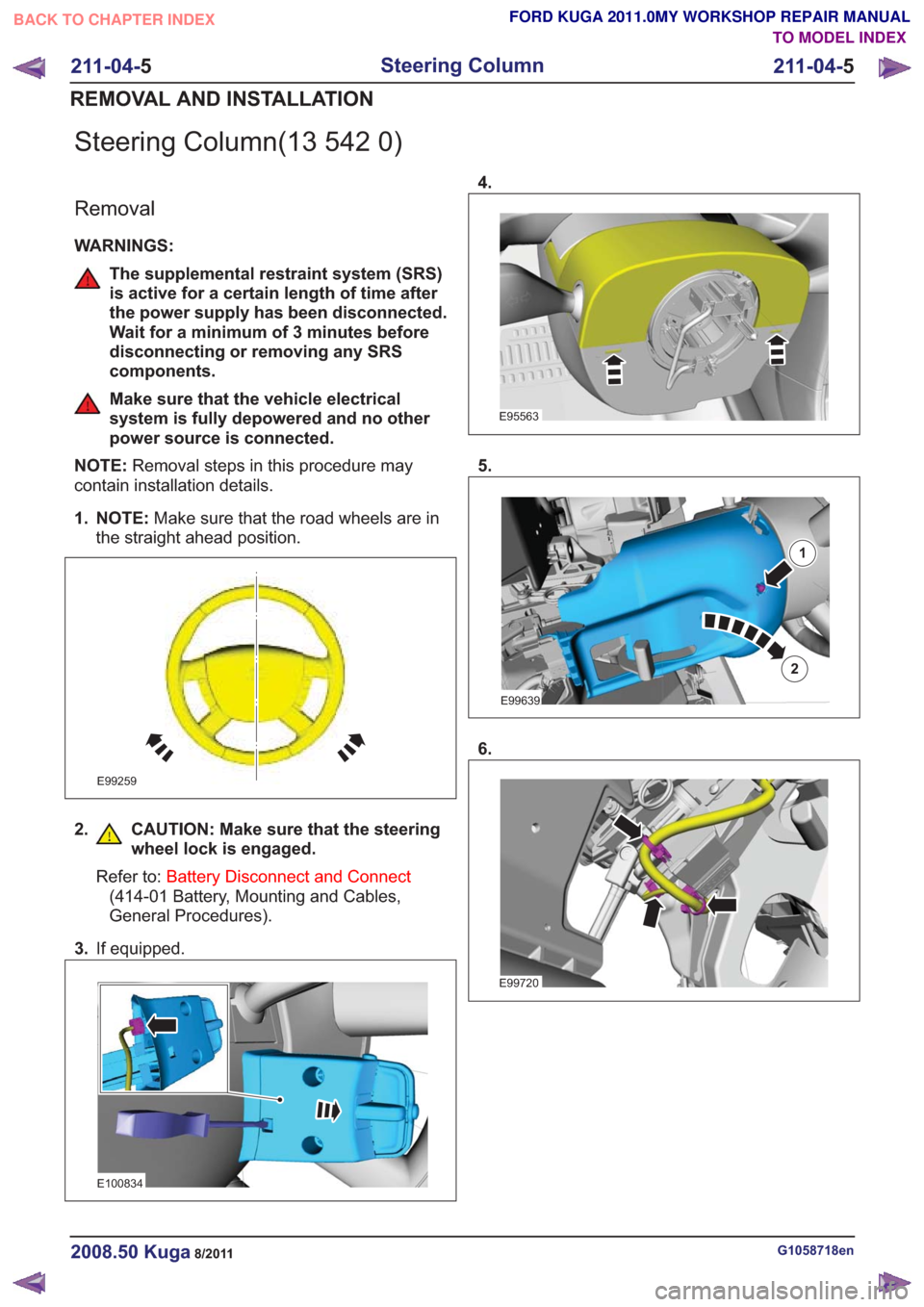
Steering Column(13 542 0)
Removal
WARNINGS:
The supplemental restraint system (SRS)
is active for a certain length of time after
the power supply has been disconnected.
Wait for a minimum of 3 minutes before
disconnecting or removing any SRS
components.
Make sure that the vehicle electrical
system is fully depowered and no other
power source is connected.
NOTE: Removal steps in this procedure may
contain installation details.
1. NOTE: Make sure that the road wheels are in
the straight ahead position.
E99259
2. CAUTION: Make sure that the steering wheel lock is engaged.
Refer to: Battery Disconnect and Connect
(414-01 Battery, Mounting and Cables,
General Procedures).
3. If equipped.
E100834
4.
E95563
5.
E99639
1
2
6.
E99720
G1058718en2008.50 Kuga8/2011
211-04- 5
Steering Column
211-04- 5
REMOVAL AND INSTALLATION
TO MODEL INDEX
BACK TO CHAPTER INDEX
FORD KUGA 2011.0MY WORKSHOP REPAIR MANUAL
Page 1507 of 2057
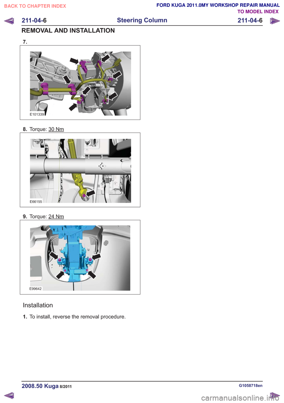
7.
E101339
8.Torque: 30Nm
E66155
9.Torque: 24Nm
E99642
Installation
1.To install, reverse the removal procedure.
G1058718en2008.50 Kuga8/2011
211-04- 6
Steering Column
211-04- 6
REMOVAL AND INSTALLATION
TO MODEL INDEX
BACK TO CHAPTER INDEX
FORD KUGA 2011.0MY WORKSHOP REPAIR MANUAL
Page 1508 of 2057
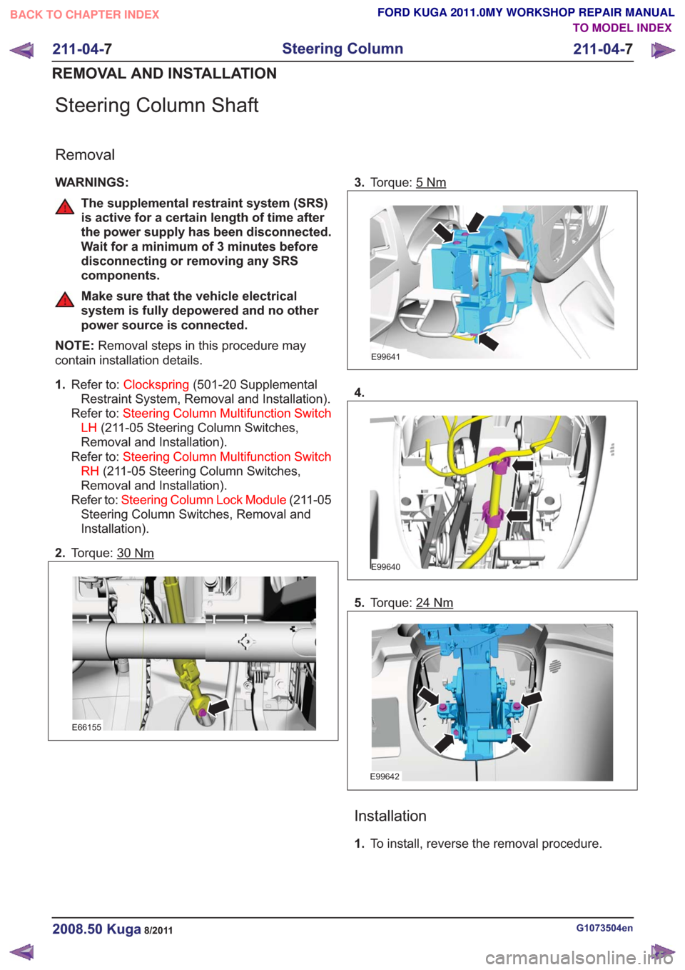
Steering Column Shaft
Removal
WARNINGS:
The supplemental restraint system (SRS)
is active for a certain length of time after
the power supply has been disconnected.
Wait for a minimum of 3 minutes before
disconnecting or removing any SRS
components.
Make sure that the vehicle electrical
system is fully depowered and no other
power source is connected.
NOTE: Removal steps in this procedure may
contain installation details.
1. Refer to: Clockspring (501-20 Supplemental
Restraint System, Removal and Installation).
Refer to: Steering Column Multifunction Switch
LH (211-05 Steering Column Switches,
Removal and Installation).
Refer to: Steering Column Multifunction Switch
RH (211-05 Steering Column Switches,
Removal and Installation).
Refer to: Steering Column Lock Module (211-05
Steering Column Switches, Removal and
Installation).
2. Torque: 30
Nm
E66155
3.Torque: 5Nm
E99641
4.
E99640
5.Torque: 24Nm
E99642
Installation
1.To install, reverse the removal procedure.
G1073504en2008.50 Kuga8/2011
211-04- 7
Steering Column
211-04- 7
REMOVAL AND INSTALLATION
TO MODEL INDEX
BACK TO CHAPTER INDEX
FORD KUGA 2011.0MY WORKSHOP REPAIR MANUAL
Page 1509 of 2057
SECTION 211-05 Steering Column Switches
VEHICLE APPLICATION:2008.50 Kuga
PA G E
CONTENTS
DESCRIPTION AND OPERATION
211-05-2
Steering Column Switches (Component Location) .............................................................
211-05-3
Steering Column Switches (Overview) ........................................................................\
.......
211-05-3
Switch unit, steering column ........................................................................\
.......................
211-05-3
Clockspring ........................................................................\
.................................................
REMOVAL AND INSTALLATION 211-05-4
Steering Column Lock Module ........................................................................\
...................
211-05-6
Steering Column Multifunction Switch LH ........................................................................\
..
211-05-7
Steering Column Multifunction Switch RH ........................................................................\
..
211-05-1
Steering Column Switches
211-05- 1
.
TO MODEL INDEX
BACK TO CHAPTER INDEX
FORD KUGA 2011.0MY WORKSHOP REPAIR MANUAL
Page 1510 of 2057
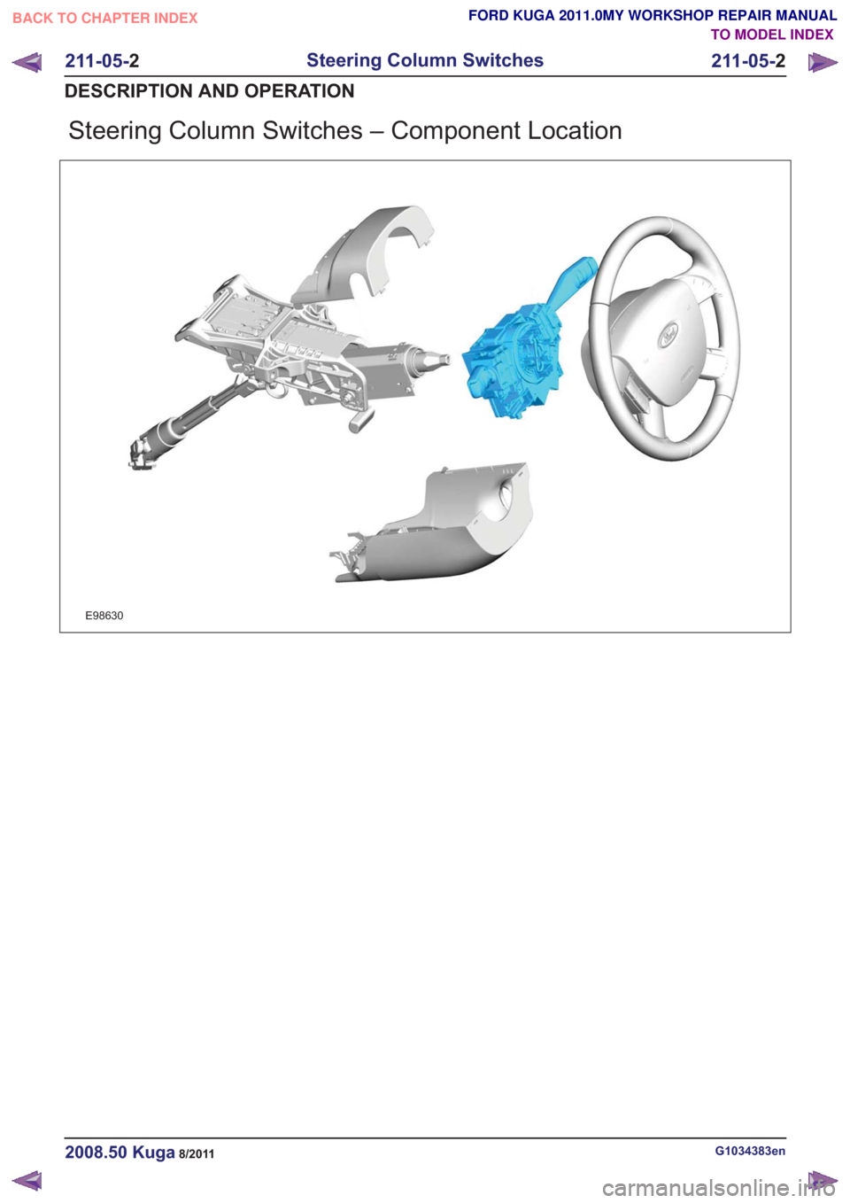
Steering Column Switches – Component Location
E98630
G1034383en2008.50 Kuga8/2011
211-05-2
Steering Column Switches
211-05- 2
DESCRIPTION AND OPERATION
TO MODEL INDEX
BACK TO CHAPTER INDEX
FORD KUGA 2011.0MY WORKSHOP REPAIR MANUAL