connector FORD KUGA 2011 1.G User Guide
[x] Cancel search | Manufacturer: FORD, Model Year: 2011, Model line: KUGA, Model: FORD KUGA 2011 1.GPages: 2057
Page 216 of 2057
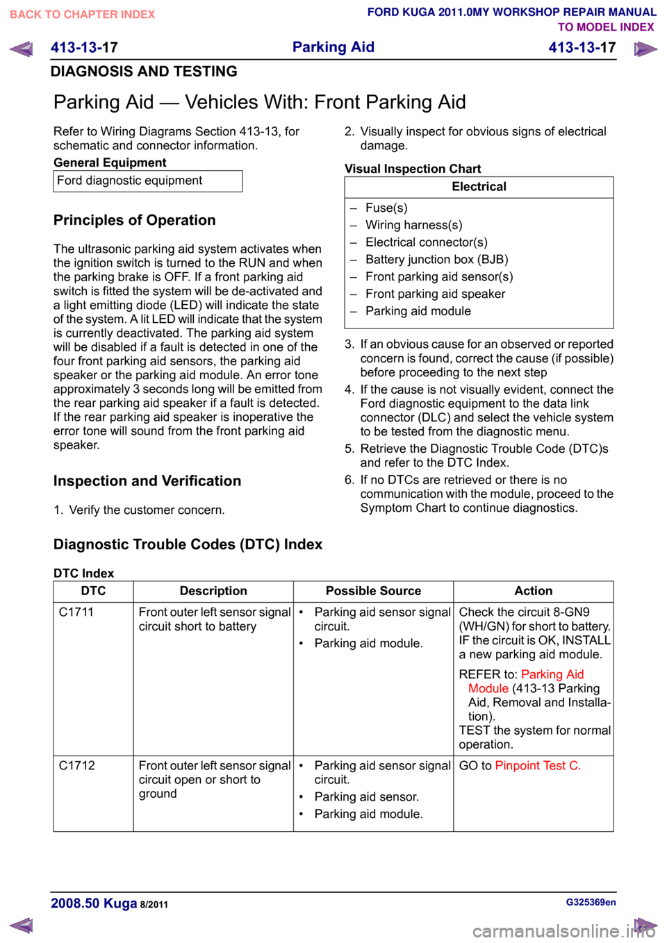
Parking Aid — Vehicles With: Front Parking Aid
Refer to Wiring Diagrams Section 413-13, for
schematic and connector information.
General Equipment
Ford diagnostic equipment
Principles of Operation
The ultrasonic parking aid system activates when
the ignition switch is turned to the RUN and when
the parking brake is OFF. If a front parking aid
switch is fitted the system will be de-activated and
a light emitting diode (LED) will indicate the state
of the system. A lit LED will indicate that the system
is currently deactivated. The parking aid system
will be disabled if a fault is detected in one of the
four front parking aid sensors, the parking aid
speaker or the parking aid module. An error tone
approximately 3 seconds long will be emitted from
the rear parking aid speaker if a fault is detected.
If the rear parking aid speaker is inoperative the
error tone will sound from the front parking aid
speaker.
Inspection and Verification
1. Verify the customer concern. 2. Visually inspect for obvious signs of electrical
damage.
Visual Inspection Chart Electrical
– Fuse(s)
– Wiring harness(s)
– Electrical connector(s)
– Battery junction box (BJB)
– Front parking aid sensor(s)
– Front parking aid speaker
– Parking aid module
3. If an obvious cause for an observed or reported concern is found, correct the cause (if possible)
before proceeding to the next step
4. If the cause is not visually evident, connect the Ford diagnostic equipment to the data link
connector (DLC) and select the vehicle system
to be tested from the diagnostic menu.
5. Retrieve the Diagnostic Trouble Code (DTC)s and refer to the DTC Index.
6. If no DTCs are retrieved or there is no communication with the module, proceed to the
Symptom Chart to continue diagnostics.
Diagnostic Trouble Codes (DTC) Index
DTC Index Action
Possible Source
Description
DTC
Check the circuit 8-GN9
(WH/GN) for short to battery.
IF the circuit is OK, INSTALL
a new parking aid module.
REFER to:Parking Aid
Module (413-13 Parking
Aid, Removal and Installa-
tion).
TEST the system for normal
operation.
• Parking aid sensor signal
circuit.
• Parking aid module.
Front outer left sensor signal
circuit short to battery
C1711
GO toPinpoint Test C.
• Parking aid sensor signal
circuit.
• Parking aid sensor.
• Parking aid module.
Front outer left sensor signal
circuit open or short to
ground
C1712 G325369en
2008.50 Kuga 8/2011 413-13-17
Parking Aid
413-13-17
DIAGNOSIS AND TESTINGTO MODEL INDEX
BACK TO CHAPTER INDEX
FORD KUGA 2011.0MY WORKSHOP REPAIR MANUAL
Page 228 of 2057
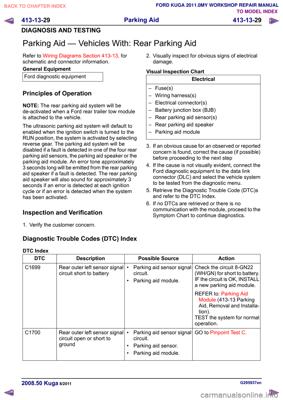
Parking Aid — Vehicles With: Rear Parking Aid
Refer to
Wiring Diagrams Section 413-13, for
schematic and connector information. General Equipment
Ford diagnostic equipment
Principles of Operation
NOTE: The rear parking aid system will be
de-activated when a Ford rear trailer tow module
is attached to the vehicle.
The ultrasonic parking aid system will default to
enabled when the ignition switch is turned to the
RUN position, the system is activated by selecting
reverse gear. The parking aid system will be
disabled if a fault is detected in one of the four rear
parking aid sensors, the parking aid speaker or the
parking aid module. An error tone approximately
3 seconds long will be emitted from the rear parking
aid speaker if a fault is detected. The rear parking
aid speaker will also sound for approximately 3
seconds if an error is detected at each ignition
cycle or if an error is detected when the system
has been activated.
Inspection and Verification
1. Verify the customer concern. 2. Visually inspect for obvious signs of electrical
damage.
Visual Inspection Chart Electrical
– Fuse(s)
– Wiring harness(s)
– Electrical connector(s)
– Battery junction box (BJB)
– Rear parking aid sensor(s)
– Rear parking aid speaker
– Parking aid module
3. If an obvious cause for an observed or reported concern is found, correct the cause (if possible)
before proceeding to the next step
4. If the cause is not visually evident, connect the Ford diagnostic equipment to the data link
connector (DLC) and select the vehicle system
to be tested from the diagnostic menu.
5. Retrieve the Diagnostic Trouble Code (DTC)s and refer to the DTC Index.
6. If no DTCs are retrieved or there is no communication with the module, proceed to the
Symptom Chart to continue diagnostics.
Diagnostic Trouble Codes (DTC) Index
DTC Index Action
Possible Source
Description
DTC
Check the circuit 8-GN22
(WH/GN) for short to battery.
IF the circuit is OK, INSTALL
a new parking aid module.
REFER to:Parking Aid
Module (413-13 Parking
Aid, Removal and Installa-
tion).
TEST the system for normal
operation.
• Parking aid sensor signal
circuit.
• Parking aid module.
Rear outer left sensor signal
circuit short to battery
C1699
GO toPinpoint Test C.
• Parking aid sensor signal
circuit.
• Parking aid sensor.
• Parking aid module.
Rear outer left sensor signal
circuit open or short to
ground
C1700 G295937en
2008.50 Kuga 8/2011 413-13-29
Parking Aid
413-13-29
DIAGNOSIS AND TESTINGTO MODEL INDEX
BACK TO CHAPTER INDEX
FORD KUGA 2011.0MY WORKSHOP REPAIR MANUAL
Page 263 of 2057
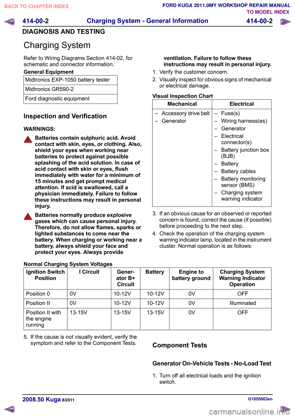
Charging System
Refer to Wiring Diagrams Section 414-02, for
schematic and connector information.
General Equipment
Midtronics EXP-1050 battery tester
Midtronics GR590-2
Ford diagnostic equipment
Inspection and Verification
WARNINGS: Batteries contain sulphuric acid. Avoid
contact with skin, eyes, or clothing. Also,
shield your eyes when working near
batteries to protect against possible
splashing of the acid solution. In case of
acid contact with skin or eyes, flush
immediately with water for a minimum of
15 minutes and get prompt medical
attention. If acid is swallowed, call a
physician immediately. Failure to follow
these instructions may result in personal
injury.
Batteries normally produce explosive
gases which can cause personal injury.
Therefore, do not allow flames, sparks or
lighted substances to come near the
battery. When charging or working near a
battery, always shield your face and
protect your eyes. Always provide
ventilation. Failure to follow these
instructions may result in personal injury.
1. Verify the customer concern.
2. Visually inspect for obvious signs of mechanical
or electrical damage.
Visual Inspection Chart Electrical
Mechanical
– Fuse(s)
– Wiring harness(es)
– Generator
– Electricalconnector(s)
– Battery junction box (BJB)
– Battery
– Battery cables
– Battery monitoring sensor (BMS)
– Charging system warning indicator
–
Accessory drive belt
– Generator
3. If an obvious cause for an observed or reported concern is found, correct the cause (if possible)
before proceeding to the next step.
4. Check the operation of the charging system warning indicator lamp, located in the instrument
cluster. Normal operation is as follows:
Normal Charging System Voltages Charging System
Warning Indicator Operation
Engine to
battery ground
Battery
Gener-
ator B+ Circuit
I Circuit
Ignition Switch
Position
OFF
0V
10-12V
10-12V
0V
Position 0
Illuminated
0V
10-12V
10-12V
0V
Position II
OFF
0V
13-15V
13-15V
13-15V
Position II with
the engine
running
5. If the cause is not visually evident, verify the symptom and refer to the Component Tests. Component Tests
Generator On-Vehicle Tests - No-Load Test
1. Turn off all electrical loads and the ignition
switch. G1055063en
2008.50 Kuga 8/2011 414-00-2
Charging System - General Information
414-00-2
DIAGNOSIS AND TESTINGTO MODEL INDEX
BACK TO CHAPTER INDEX
FORD KUGA 2011.0MY WORKSHOP REPAIR MANUAL
Page 281 of 2057
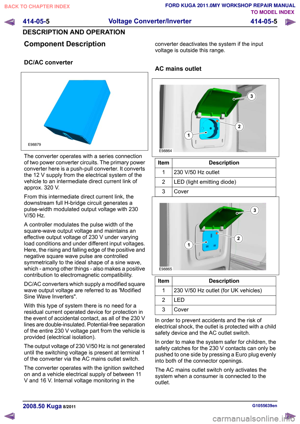
Component Description
DC/AC converter
The converter operates with a series connection
of two power converter circuits. The primary power
converter here is a push-pull converter. It converts
the 12 V supply from the electrical system of the
vehicle to an intermediate direct current link of
approx. 320 V.
From this intermediate direct current link, the
downstream full H-bridge circuit generates a
pulse-width modulated output voltage with 230
V/50 Hz.
A controller modulates the pulse width of the
square-wave output voltage and maintains an
effective output voltage of 230 V under varying
load conditions and under different input voltages.
Here, the rising and falling edge of the positive and
negative square wave pulse are controlled
symmetrically to the ideal shape of a sine wave,
which - among other things - also makes a positive
contribution to electromagnetic compatibility.
DC/AC converters which supply a modified square
wave output voltage are referred to as 'Modified
Sine Wave Inverters".
With this type of system there is no need for a
residual current operated device for protection in
the event of accidental contact, as all of the 230 V
lines are double-insulated. Potential-free separation
of the entire 230 V voltage part from the vehicle is
provided (electrical isolation).
The output voltage of 230 V/50 Hz is not generated
until the switching voltage is present at terminal 1
of the converter via the AC mains outlet switch.
The converter operates with the ignition switched
on and a vehicle electrical supply of between 11
V and 16 V. Internal voltage monitoring in the converter deactivates the system if the input
voltage is outside this range.
AC mains outlet
Description
Item
230 V/50 Hz outlet
1
LED (light emitting diode)
2
Cover3 Description
Item
230 V/50 Hz outlet (for UK vehicles)
1
LED2
Cover3
In order to prevent accidents and the risk of
electrical shock, the outlet is protected with a child
safety device and the AC outlet switch.
In order to make the system safer for children, the
safety catches for the 230 V contacts can only be
pushed to one side by pressing a Euro plug evenly
into both of the connector openings.
The AC mains outlet switch only activates the
system when a consumer is connected to the
outlet. G1055639en
2008.50 Kuga 8/2011 414-05-5
Voltage Converter/Inverter
414-05-5
DESCRIPTION AND OPERATIONTO MODEL INDEX
BACK TO CHAPTER INDEX
FORD KUGA 2011.0MY WORKSHOP REPAIR MANUALE98879 E98864312 E98865312
Page 288 of 2057
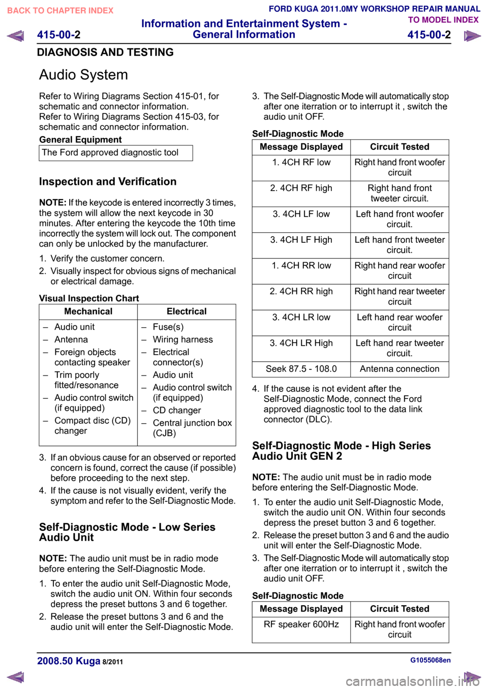
Audio System
Refer to Wiring Diagrams Section 415-01, for
schematic and connector information.
Refer to Wiring Diagrams Section 415-03, for
schematic and connector information.
General Equipment
The Ford approved diagnostic tool
Inspection and Verification
NOTE: If the keycode is entered incorrectly 3 times,
the system will allow the next keycode in 30
minutes. After entering the keycode the 10th time
incorrectly the system will lock out. The component
can only be unlocked by the manufacturer.
1. Verify the customer concern.
2. Visually inspect for obvious signs of mechanical
or electrical damage.
Visual Inspection Chart Electrical
Mechanical
– Fuse(s)
– Wiring harness
– Electricalconnector(s)
– Audio unit
– Audio control switch (if equipped)
– CD changer
– Central junction box (CJB)
– Audio unit
– Antenna
– Foreign objects
contacting speaker
– Trim poorly fitted/resonance
– Audio control switch (if equipped)
– Compact disc (CD) changer
3. If an obvious cause for an observed or reported concern is found, correct the cause (if possible)
before proceeding to the next step.
4. If the cause is not visually evident, verify the symptom and refer to the Self-Diagnostic Mode.
Self-Diagnostic Mode - Low Series
Audio Unit
NOTE: The audio unit must be in radio mode
before entering the Self-Diagnostic Mode.
1. To enter the audio unit Self-Diagnostic Mode, switch the audio unit ON. Within four seconds
depress the preset buttons 3 and 6 together.
2. Release the preset buttons 3 and 6 and the audio unit will enter the Self-Diagnostic Mode. 3.
The Self-Diagnostic Mode will automatically stop
after one iterration or to interrupt it , switch the
audio unit OFF.
Self-Diagnostic Mode Circuit Tested
Message Displayed
Right hand front woofercircuit
1. 4CH RF low
Right hand fronttweeter circuit.
2. 4CH RF high
Left hand front woofercircuit.
3. 4CH LF low
Left hand front tweetercircuit.
3. 4CH LF High
Right hand rear woofercircuit
1. 4CH RR low
Right hand rear tweetercircuit
2. 4CH RR high
Left hand rear woofercircuit
3. 4CH LR low
Left hand rear tweetercircuit.
3. 4CH LR High
Antenna connection
Seek 87.5 - 108.0
4. If the cause is not evident after the Self-Diagnostic Mode, connect the Ford
approved diagnostic tool to the data link
connector (DLC).
Self-Diagnostic Mode - High Series
Audio Unit GEN 2
NOTE: The audio unit must be in radio mode
before entering the Self-Diagnostic Mode.
1. To enter the audio unit Self-Diagnostic Mode, switch the audio unit ON. Within four seconds
depress the preset button 3 and 6 together.
2. Release the preset button 3 and 6 and the audio
unit will enter the Self-Diagnostic Mode.
3. The Self-Diagnostic Mode will automatically stop
after one iterration or to interrupt it , switch the
audio unit OFF.
Self-Diagnostic Mode Circuit Tested
Message Displayed
Right hand front woofercircuit
RF speaker 600Hz G1055068en
2008.50 Kuga 8/2011 415-00-2
Information and Entertainment System -
General Information
415-00-2
DIAGNOSIS AND TESTINGTO MODEL INDEX
BACK TO CHAPTER INDEX
FORD KUGA 2011.0MY WORKSHOP REPAIR MANUAL
Page 290 of 2057
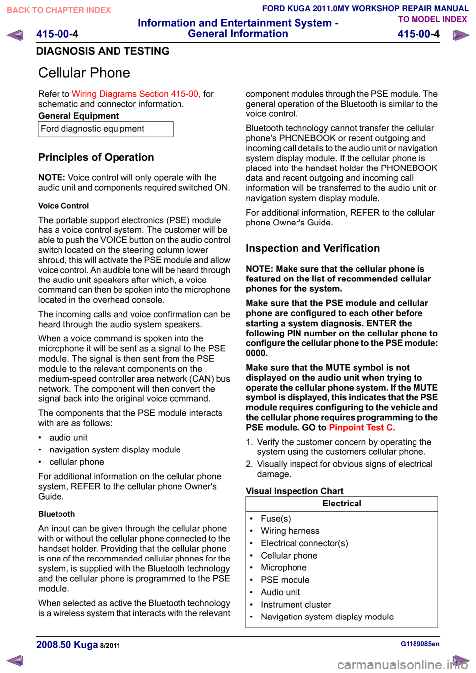
Cellular Phone
Refer to
Wiring Diagrams Section 415-00, for
schematic and connector information. General Equipment
Ford diagnostic equipment
Principles of Operation
NOTE: Voice control will only operate with the
audio unit and components required switched ON.
Voice Control
The portable support electronics (PSE) module
has a voice control system. The customer will be
able to push the VOICE button on the audio control
switch located on the steering column lower
shroud, this will activate the PSE module and allow
voice control. An audible tone will be heard through
the audio unit speakers after which, a voice
command can then be spoken into the microphone
located in the overhead console.
The incoming calls and voice confirmation can be
heard through the audio system speakers.
When a voice command is spoken into the
microphone it will be sent as a signal to the PSE
module. The signal is then sent from the PSE
module to the relevant components on the
medium-speed controller area network (CAN) bus
network. The component will then convert the
signal back into the original voice command.
The components that the PSE module interacts
with are as follows:
• audio unit
• navigation system display module
• cellular phone
For additional information on the cellular phone
system, REFER to the cellular phone Owner's
Guide.
Bluetooth
An input can be given through the cellular phone
with or without the cellular phone connected to the
handset holder. Providing that the cellular phone
is one of the recommended cellular phones for the
system, is supplied with the Bluetooth technology
and the cellular phone is programmed to the PSE
module.
When selected as active the Bluetooth technology
is a wireless system that interacts with the relevant component modules through the PSE module. The
general operation of the Bluetooth is similar to the
voice control.
Bluetooth technology cannot transfer the cellular
phone's PHONEBOOK or recent outgoing and
incoming call details to the audio unit or navigation
system display module. If the cellular phone is
placed into the handset holder the PHONEBOOK
data and recent outgoing and incoming call
information will be transferred to the audio unit or
navigation system display module.
For additional information, REFER to the cellular
phone Owner's Guide.
Inspection and Verification
NOTE: Make sure that the cellular phone is
featured on the list of recommended cellular
phones for the system.
Make sure that the PSE module and cellular
phone are configured to each other before
starting a system diagnosis. ENTER the
following PIN number on the cellular phone to
configure the cellular phone to the PSE module:
0000.
Make sure that the MUTE symbol is not
displayed on the audio unit when trying to
operate the cellular phone system. If the MUTE
symbol is displayed, this indicates that the PSE
module requires configuring to the vehicle and
the cellular phone requires programming to the
PSE module. GO to
Pinpoint Test C.
1. Verify the customer concern by operating the system using the customers cellular phone.
2. Visually inspect for obvious signs of electrical damage.
Visual Inspection Chart Electrical
• Fuse(s)
• Wiring harness
• Electrical connector(s)
• Cellular phone
• Microphone
• PSE module
• Audio unit
• Instrument cluster
• Navigation system display module G1189085en
2008.50 Kuga 8/2011 415-00-4
Information and Entertainment System -
General Information
415-00-4
DIAGNOSIS AND TESTINGTO MODEL INDEX
BACK TO CHAPTER INDEX
FORD KUGA 2011.0MY WORKSHOP REPAIR MANUAL
Page 291 of 2057
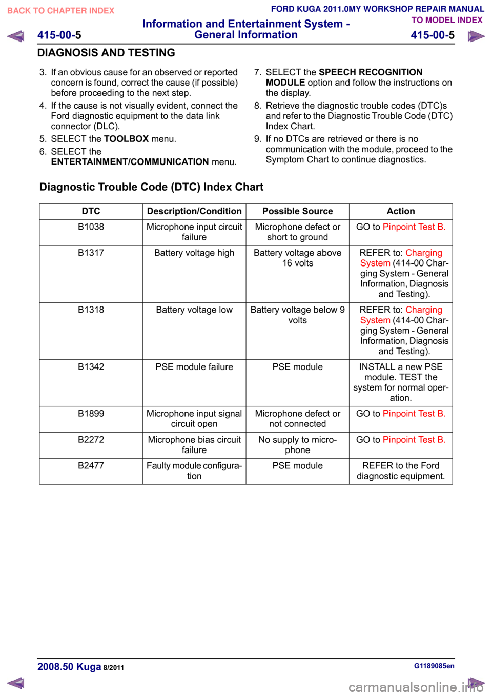
3. If an obvious cause for an observed or reported
concern is found, correct the cause (if possible)
before proceeding to the next step.
4. If the cause is not visually evident, connect the Ford diagnostic equipment to the data link
connector (DLC).
5. SELECT the TOOLBOXmenu.
6. SELECT the ENTERTAINMENT/COMMUNICATION menu.7. SELECT the
SPEECH RECOGNITION
MODULE option and follow the instructions on
the display.
8. Retrieve the diagnostic trouble codes (DTC)s and refer to the Diagnostic Trouble Code (DTC)
Index Chart.
9. If no DTCs are retrieved or there is no communication with the module, proceed to the
Symptom Chart to continue diagnostics.
Diagnostic Trouble Code (DTC) Index Chart Action
Possible Source
Description/Condition
DTC
GO toPinpoint Test B.
Microphone defect or
short to ground
Microphone input circuit
failure
B1038
REFER to:Charging
System (414-00 Char-
ging System - General
Information, Diagnosis and Testing).
Battery voltage above
16 volts
Battery voltage high
B1317
REFER to:Charging
System (414-00 Char-
ging System - General
Information, Diagnosis and Testing).
Battery voltage below 9
volts
Battery voltage low
B1318
INSTALL a new PSEmodule. TEST the
system for normal oper- ation.
PSE module
PSE module failure
B1342
GO toPinpoint Test B.
Microphone defect or
not connected
Microphone input signal
circuit open
B1899
GO toPinpoint Test B.
No supply to micro-
phone
Microphone bias circuit
failure
B2272
REFER to the Ford
diagnostic equipment.
PSE module
Faulty module configura-
tion
B2477 G1189085en
2008.50 Kuga 8/2011 415-00-5
Information and Entertainment System -
General Information
415-00-5
DIAGNOSIS AND TESTINGTO MODEL INDEX
BACK TO CHAPTER INDEX
FORD KUGA 2011.0MY WORKSHOP REPAIR MANUAL
Page 297 of 2057

SECTION 415-01 Information and Entertainment
System
VEHICLE APPLICATION:
2008.50 Kuga
PAGE
CONTENTS
DESCRIPTION AND OPERATION
415-01-2
Audio System (Component Location).................................................................................
415-01-3
Audio System (Overview)...................................................................................................
415-01-3
Keycode entry - vehicle with standard audio system.........................................................
415-01-3
Vehicle Identification Number (VID) - entry - vehicle with standard audio system.............
415-01-3
Self-check routine - vehicles with standard audio system..................................................
415-01-3
Keycode entry - vehicles with upgraded audio system......................................................
415-01-5
Audio System (System Operation and Component Description)........................................
415-01-5
System Diagram.................................................................................................................
415-01-8
System Operation...............................................................................................................
415-01-8
In-car entertainment........................................................................................................
415-01-8
Component Description......................................................................................................
415-01-8
Vehicles with standard audio system..............................................................................
415-01-9
Vehicles with upgraded audio system.............................................................................
415-01-9
DAB radio........................................................................................................................
415-01-9
AUX port.........................................................................................................................
415-01-9
Radio remote control......................................................................................................415-01-10Antenna systems............................................................................................................
415-01-11
Cellular Phone (Component Location)...............................................................................
415-01-12
Cellular Phone (Overview)..................................................................................................
415-01-12
Software update - control module for mobile electronic auxiliary equipment (variant 1)....
415-01-12
Software update - control module for mobile electronic auxiliary equipment (variants 2
and 3)................................................................................................................................ 415-01-13
Cellular Phone (System Operation and Component Description)......................................
415-01-13
System Diagram.................................................................................................................
415-01-17
System Operation...............................................................................................................
415-01-17
Overview .........................................................................................................................
415-01-17
Voice Control...................................................................................................................
415-01-18
Component Description......................................................................................................
415-01-18Control module for mobile electronic auxiliary equipment..............................................
415-01-19Radio remote control......................................................................................................
415-01-19USB port/AUX socket.....................................................................................................
REMOVAL AND INSTALLATION 415-01-20
Audio Unit...........................................................................................................................
415-01-21
Audio Unit Antenna — Vehicles With: Glass Roof Panel...................................................
415-01-22
Audio Unit Antenna — Vehicles Without: Glass Roof Panel..............................................
415-01-23
Audio Unit Antenna to Connector Cable — Vehicles With: Glass Roof Panel...................
415-01-30
Audio Unit Antenna to Connector Cable — Vehicles Without: Glass Roof Panel..............
415-01-32
Connector to Audio Unit Antenna Cable.............................................................................
415-01-35
Compact Disc (CD) Changer..............................................................................................
415-01-37
(33 635 0)
Portable Support Electronics (PSE) Module..................................................
415-01-38
Cellular Phone Microphone................................................................................................ 415-01-1
Information and Entertainment System
415-01-1
.
TO MODEL INDEX
BACK TO CHAPTER INDEX
FORD KUGA 2011.0MY WORKSHOP REPAIR MANUAL
Page 319 of 2057
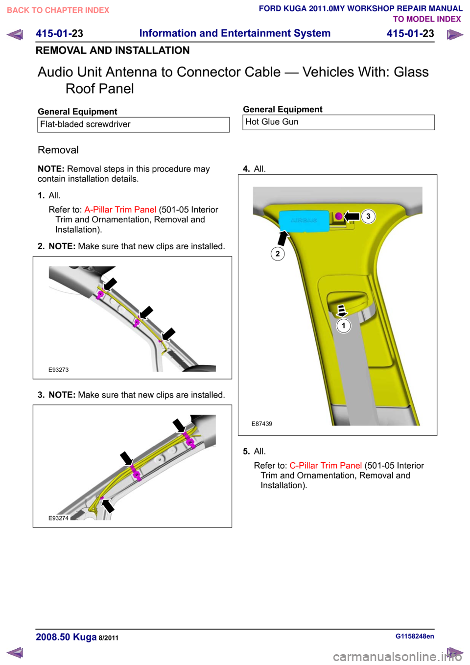
Audio Unit Antenna to Connector Cable — Vehicles With: Glass
Roof Panel General Equipment
Flat-bladed screwdriver General Equipment
Hot Glue Gun
Removal
NOTE: Removal steps in this procedure may
contain installation details.
1. All.
Refer to: A-Pillar Trim Panel (501-05 Interior
Trim and Ornamentation, Removal and
Installation).
2. NOTE: Make sure that new clips are installed.3. NOTE:
Make sure that new clips are installed. 4.
All. 5.
All.
Refer to: C-Pillar Trim Panel (501-05 Interior
Trim and Ornamentation, Removal and
Installation). G1158248en
2008.50 Kuga 8/2011 415-01-23
Information and Entertainment System
415-01-23
REMOVAL AND INSTALLATIONTO MODEL INDEX
BACK TO CHAPTER INDEX
FORD KUGA 2011.0MY WORKSHOP REPAIR MANUALE93273 E93274 123E87439
Page 326 of 2057
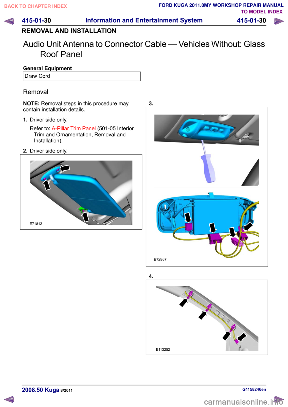
Audio Unit Antenna to Connector Cable — Vehicles Without: Glass
Roof Panel General Equipment
Draw Cord
Removal
NOTE: Removal steps in this procedure may
contain installation details.
1. Driver side only.
Refer to: A-Pillar Trim Panel (501-05 Interior
Trim and Ornamentation, Removal and
Installation).
2. Driver side only. 3.
4.
G1158246en
2008.50 Kuga 8/2011 415-01-30
Information and Entertainment System
415-01-30
REMOVAL AND INSTALLATIONTO MODEL INDEX
BACK TO CHAPTER INDEX
FORD KUGA 2011.0MY WORKSHOP REPAIR MANUALE71812 E72967 E113252