fluid FORD KUGA 2011 1.G User Guide
[x] Cancel search | Manufacturer: FORD, Model Year: 2011, Model line: KUGA, Model: FORD KUGA 2011 1.GPages: 2057
Page 67 of 2057
Brake System Health and Safety Precautions
WARNINGS:
EYE CONTACT: Brake fluid contains
polyglycol ethers and polyglycols. Avoid
contact with the eyes. Wash hands
thoroughly after handling. If brake fluid
comes into contact with the eyes, flush the
eyes with plenty of cold running water for
15 minutes. Seek medical attention for any
persistent eye irritation or abnormality.
SWALLOWED: Brake fluid contains
polyglycol ethers and polyglycols. If
swallowed, drink plenty of water. Seek
immediate medical attention.
INHALED: Dust from friction materials can
be harmful if inhaled.
Only use new specified brake fluid from
airtight containers.
CAUTION: If brake fluid is spilled on the
paintwork, the affected area must be
immediately washed down with cold water.
G565862en2008.50 Kuga8/2011
100-00-62
General Information
100-00- 62
DESCRIPTION AND OPERATION
TO MODEL INDEX
BACK TO CHAPTER INDEX
FORD KUGA 2011.0MY WORKSHOP REPAIR MANUAL
Page 68 of 2057
Engine Cooling System Health and Safety Precautions
WARNINGS:
Extreme care must be exercised when
handling hot fluids. Always wash off spilled
fluids from affected areas of skin
immediately.
Vapors may be given off from antifreeze
when heated. Avoid breathing these
vapors.
SKIN CONTACT: Antifreeze may be
absorbed through the skin in toxic or
harmful quantities.
SWALLOWED: If antifreeze is swallowed,
drink plenty of water, induce vomiting.
Seek immediate medical attention.
Antifreeze must not be used in any cooling
or industrial water system that is
connected or linked to general water
supplies.
G548995en2008.50 Kuga8/2011
100-00-63
General Information
100-00- 63
DESCRIPTION AND OPERATION
TO MODEL INDEX
BACK TO CHAPTER INDEX
FORD KUGA 2011.0MY WORKSHOP REPAIR MANUAL
Page 70 of 2057
Petrol and Petrol-Ethanol Fuel Systems Health and SafetyPrecautions
WARNINGS:
Fuel may not give adequate warning before
toxic or harmful effects arise.
Exposure to fuel can be harmful and can
cause severe health damage or death.
Extreme care must be exercised when
handling hot fluids. Always wash off spilled
fluids from affected areas of skin
immediately.
Highly flammable mixtures are always
present and may ignite when working on
fuel systems. Do not allow naked flames,
sparks or lighted substances to come near
fuel related components.
Fuel must not be used as a cleaning agent.
Keep fuel containers tightly closed, out of
direct sunlight and in a cool area. Keep
away from heat sources, ignition sources
and oxidizing agents.
SKIN CONTACT: Excessive or prolonged
skin contact with diesel fuel may cause
serious skin disorders including skin
cancer.
SKIN CONTACT: Fuel is mildly irritating to
the skin and may cause dermatitis due to
defatting effect. Remove contaminated
clothing. Wash affected areas of skin with
soap and water. Seek medical attention for
any persistent skin irritation or
abnormality. Wash contaminated clothing
before reuse.
EYE CONTACT: Fuel is mildly irritating to
the eyes. Flush with plenty of running
water, blinking as often as possible. Do not
force the eyelid open. Seek medical
attention for any persistent eye irritation
or abnormality.
SWALLOWED: Fuel is moderately toxic
and tends to foam on vomiting. If drawn
into the lungs, inflammation may develop.
Do not induce vomiting. If spontaneous
vomiting occurs place the victim in a
forward position to reduce the risk of fuel
being drawn into the lungs. Give nothing
by mouth. If breathing but unconscious,
place in the recovery position. If breathing has stopped, apply artificial respiration.
Seek immediate medical attention.
INHALED: Fuel is toxic to the respiratory
and other body systems. Exposure may
result in various symptoms including
drowsiness, unconsciousness or severe
health damage. Move a victim to fresh air.
Keep a victim warm and at rest. If
unconscious, place in the recovery
position. If not breathing, apply artificial
respiration. Give cardiac massage if
necessary. Seek immediate medical
attention.
CAUTIONS:
Fuel injection equipment is manufactured
to very precise tolerances and fine
clearances. It is essential that absolute
cleanliness is observed when working with
these components.
Make sure that the workshop area in which
the vehicle is being worked on is as clean
and as dust free as possible.
G548996en2008.50 Kuga8/2011
100-00- 64
General Information
100-00- 64
DESCRIPTION AND OPERATION
TO MODEL INDEX
BACK TO CHAPTER INDEX
FORD KUGA 2011.0MY WORKSHOP REPAIR MANUAL
Page 80 of 2057
Noise Conditions
• Gear noise is typically a howling or whining dueto gear damage or incorrect bearing preload. It
can occur at various speeds and driving
conditions, or it can be continuous.
• Chuckle is a particular rattling noise that sounds like a stick against the spokes of a spinning
bicycle wheel. It occurs while decelerating from
64 km/h (40 mph) and can usually be heard all
the way to a stop. The frequency varies with
vehicle speed.
• Knock is very similar to chuckle, though it may be louder and occurs on acceleration or
deceleration. The teardown will disclose what
has to be corrected.
Clicking, popping or grinding noises may be caused
by the following:
• worn, damaged or incorrectly installed wheel bearing, suspension or brake component.
Check and rule out tires, exhaust and trim items
before disassembling the transmission to diagnose
and correct gear noise.
The noises described under Road Test usually
have specific causes that can be diagnosed by
observation as the unit is disassembled. The initial
clues are the type of noise heard on the road test
and driving conditions.
Vibration Conditions
Vibration at highway speeds may be caused by
the following:
• out-of-balance front or rear wheels.
• out-of-round tires.
Shudder or vibration during acceleration may be
caused by the following:
• damaged powertrain/drivetrain mounts.
• excessively high constant velocity (CV) joint operating angles caused by incorrect ride height.
Check ride height, verify correct spring rate and
check items under inoperative conditions.
Road Test
A gear-driven unit will produce a certain amount
of noise. Some noise is acceptable and may be
audible at certain speeds or under various driving
conditions, as on a newly paved asphalt road. The slight noise is in no way detrimental and must be
considered normal.
The road test and customer interview (if available)
provide information needed to identify the condition
and give direction to the correct starting point for
diagnosis.
1. Make notes throughout the diagnosis routine.
Make sure to write down even the smallest bit
of information, because it may turn out to be the
most important.
2. Do not touch anything until a road test and a thorough visual inspection of the vehicle have
been carried out. Leave the tire pressures and
vehicle load just where they were when the
condition was first observed. Adjusting tire
pressures, vehicle load or making other
adjustments may reduce the condition(s)
intensity to a point where it cannot be identified
clearly. It may also inject something new into
the system, preventing correct diagnosis.
3. Make a visual inspection as part of the preliminary diagnosis routine, writing down
anything that does not look right. Note tire
pressures, but do not adjust them yet. Note
leaking fluids, loose nuts and bolts, or bright
spots where components may be rubbing
against each other. Check the load space for
unusual loads.
4. Road test the vehicle and define the condition by reproducing it several times during the road
test.
5. Carry out the Road Test Quick Checks as soon as the condition is reproduced. This will identify
the correct diagnostic procedure. Carry out the
Road Test Quick Checks more than once to
verify they are providing a valid result.
Remember, the Road Test Quick Checks may
not tell where the concern is, but they will tell
where it is not.
Road Test Quick Checks
1. 24-80 km/h (15-50 mph): with light acceleration,a moaning noise is heard and possibly a
vibration felt in the front floor panel. It is usually
worse at a particular engine speed and at a
particular throttle setting during acceleration at
that speed. It may also produce a moaning
sound, depending on what component is
causing it. REFER to Tip-in Moan in the
Driveline Noise and Vibration Symptom Chart.
2. Acceleration/Deceleration: With slow acceleration and deceleration, a shake is
G37349en2008.50 Kuga8/2011
100-04- 3
Noise, Vibration and Harshness
100-04- 3
DIAGNOSIS AND TESTING
TO MODEL INDEX
BACK TO CHAPTER INDEX
FORD KUGA 2011.0MY WORKSHOP REPAIR MANUAL
Page 85 of 2057
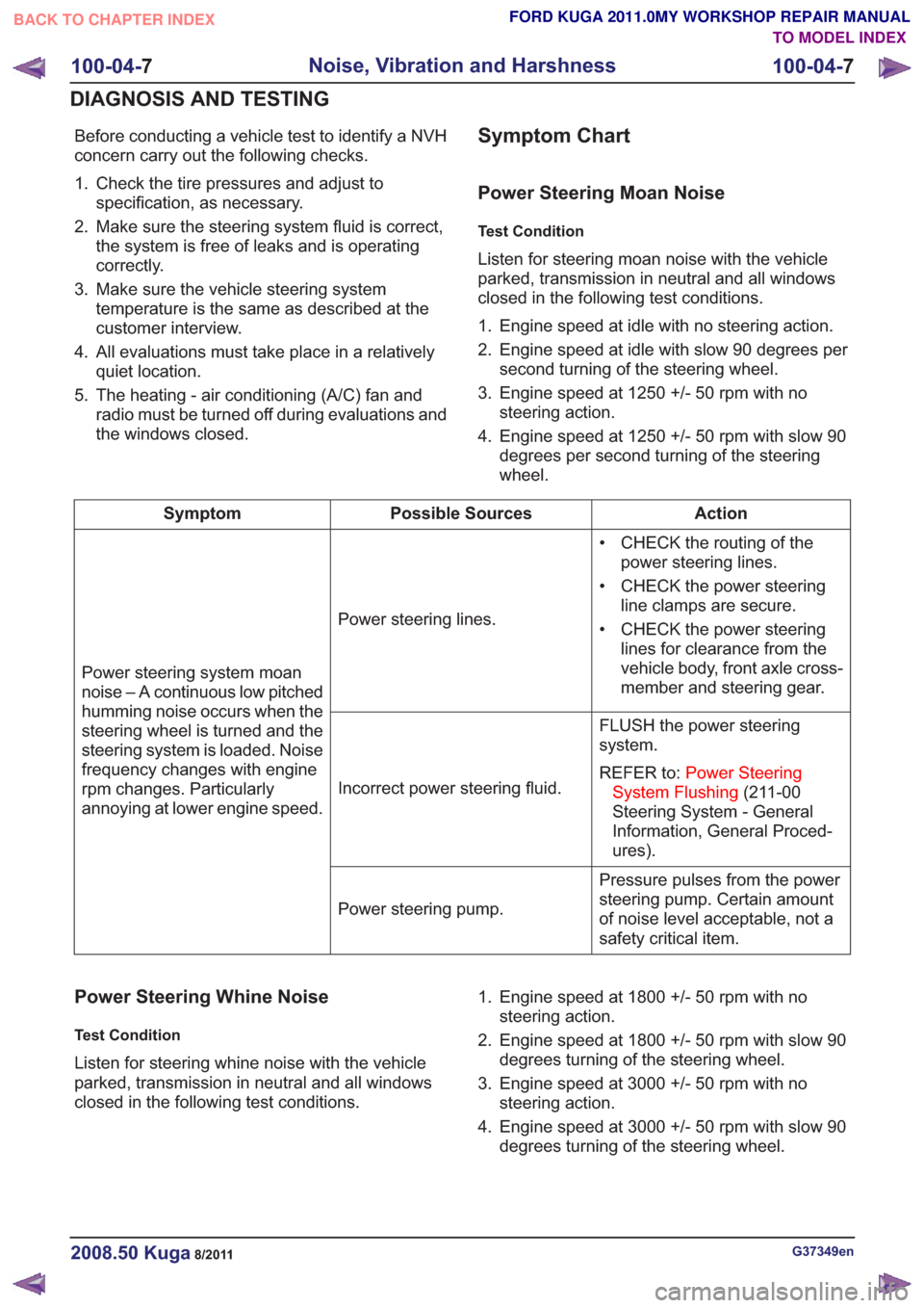
Before conducting a vehicle test to identify a NVH
concern carry out the following checks.
1. Check the tire pressures and adjust tospecification, as necessary.
2. Make sure the steering system fluid is correct, the system is free of leaks and is operating
correctly.
3. Make sure the vehicle steering system temperature is the same as described at the
customer interview.
4. All evaluations must take place in a relatively quiet location.
5. The heating - air conditioning (A/C) fan and radio must be turned off during evaluations and
the windows closed.Symptom Chart
Power Steering Moan Noise
Test Condition
Listen for steering moan noise with the vehicle
parked, transmission in neutral and all windows
closed in the following test conditions.
1. Engine speed at idle with no steering action.
2. Engine speed at idle with slow 90 degrees persecond turning of the steering wheel.
3. Engine speed at 1250 +/- 50 rpm with no steering action.
4. Engine speed at 1250 +/- 50 rpm with slow 90 degrees per second turning of the steering
wheel.
Action
Possible Sources
Symptom
• CHECK the routing of thepower steering lines.
• CHECK the power steering line clamps are secure.
• CHECK the power steering lines for clearance from the
vehicle body, front axle cross-
member and steering gear.
Power steering lines.
Power steering system moan
noise – A continuous low pitched
humming noise occurs when the
steering wheel is turned and the
steering system is loaded. Noise
frequency changes with engine
rpm changes. Particularly
annoying at lower engine speed. FLUSH the power steering
system.
REFER to:
Power Steering
System Flushing (211-00
Steering System - General
Information, General Proced-
ures).
Incorrect power steering fluid.
Pressure pulses from the power
steering pump. Certain amount
of noise level acceptable, not a
safety critical item.
Power steering pump.
Power Steering Whine Noise
Test Condition
Listen for steering whine noise with the vehicle
parked, transmission in neutral and all windows
closed in the following test conditions. 1. Engine speed at 1800 +/- 50 rpm with no
steering action.
2. Engine speed at 1800 +/- 50 rpm with slow 90 degrees turning of the steering wheel.
3. Engine speed at 3000 +/- 50 rpm with no steering action.
4. Engine speed at 3000 +/- 50 rpm with slow 90 degrees turning of the steering wheel.
G37349en2008.50 Kuga8/2011
100-04- 7
Noise, Vibration and Harshness
100-04- 7
DIAGNOSIS AND TESTING
TO MODEL INDEX
BACK TO CHAPTER INDEX
FORD KUGA 2011.0MY WORKSHOP REPAIR MANUAL
Page 86 of 2057
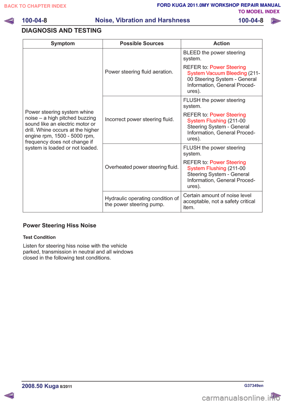
Action
Possible Sources
Symptom
BLEED the power steering
system.
REFER to:Power Steering
System Vacuum Bleeding (211-
00 Steering System - General
Information, General Proced-
ures).
Power steering fluid aeration.
Power steering system whine
noise – a high pitched buzzing
sound like an electric motor or
drill. Whine occurs at the higher
engine rpm, 1500 - 5000 rpm,
frequency does not change if
system is loaded or not loaded. FLUSH the power steering
system.
REFER to:
Power Steering
System Flushing (211-00
Steering System - General
Information, General Proced-
ures).
Incorrect power steering fluid.
FLUSH the power steering
system.
REFER to:Power Steering
System Flushing (211-00
Steering System - General
Information, General Proced-
ures).
Overheated power steering fluid.
Certain amount of noise level
acceptable, not a safety critical
item.
Hydraulic operating condition of
the power steering pump.
Power Steering Hiss Noise
Test Condition
Listen for steering hiss noise with the vehicle
parked, transmission in neutral and all windows
closed in the following test conditions.
G37349en2008.50 Kuga8/2011
100-04-
8
Noise, Vibration and Harshness
100-04- 8
DIAGNOSIS AND TESTING
TO MODEL INDEX
BACK TO CHAPTER INDEX
FORD KUGA 2011.0MY WORKSHOP REPAIR MANUAL
Page 91 of 2057
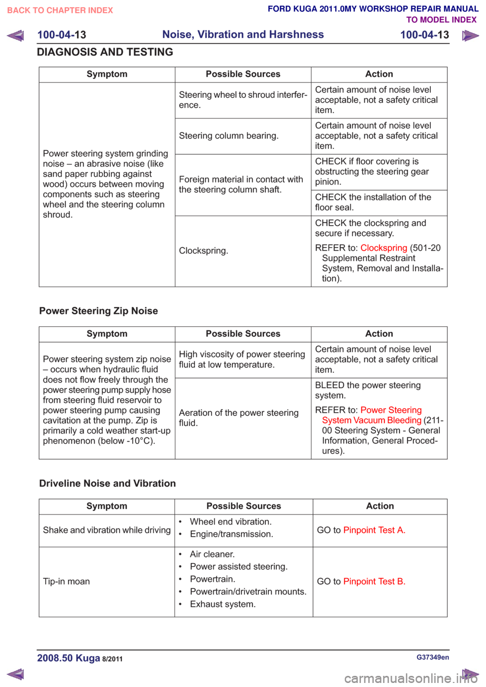
Action
Possible Sources
Symptom
Certain amount of noise level
acceptable, not a safety critical
item.
Steering wheel to shroud interfer-
ence.
Power steering system grinding
noise – an abrasive noise (like
sand paper rubbing against
wood) occurs between moving
components such as steering
wheel and the steering column
shroud. Certain amount of noise level
acceptable, not a safety critical
item.
Steering column bearing.
CHECK if floor covering is
obstructing the steering gear
pinion.
Foreign material in contact with
the steering column shaft.
CHECK the installation of the
floor seal.
CHECK the clockspring and
secure if necessary.
REFER to:Clockspring (501-20
Supplemental Restraint
System, Removal and Installa-
tion).
Clockspring.
Power Steering Zip Noise
Action
Possible Sources
Symptom
Certain amount of noise level
acceptable, not a safety critical
item.
High viscosity of power steering
fluid at low temperature.
Power steering system zip noise
– occurs when hydraulic fluid
does not flow freely through the
power steering pump supply hose
from steering fluid reservoir to
power steering pump causing
cavitation at the pump. Zip is
primarily a cold weather start-up
phenomenon (below -10°C). BLEED the power steering
system.
REFER to:
Power Steering
System Vacuum Bleeding (211-
00 Steering System - General
Information, General Proced-
ures).
Aeration of the power steering
fluid.
Driveline Noise and Vibration
Action
Possible Sources
Symptom
GO toPinpoint Test A.
• Wheel end vibration.
• Engine/transmission.
Shake and vibration while driving
GO toPinpoint Test B.
• Air cleaner.
• Power assisted steering.
• Powertrain.
• Powertrain/drivetrain mounts.
• Exhaust system.
Tip-in moan
G37349en2008.50 Kuga8/2011
100-04-
13
Noise, Vibration and Harshness
100-04- 13
DIAGNOSIS AND TESTING
TO MODEL INDEX
BACK TO CHAPTER INDEX
FORD KUGA 2011.0MY WORKSHOP REPAIR MANUAL
Page 120 of 2057
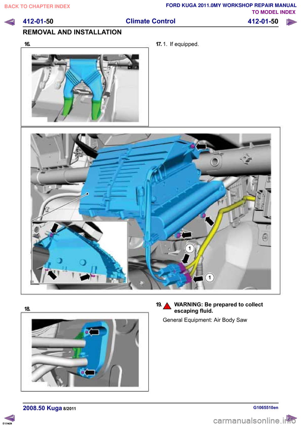
16.TO MODEL INDEX
BACK TO CHAPTER INDEX
FORD KUGA 2011.0MY WORKSHOP REPAIR MANUAL 17.
If equipped.
1.
E101425 18. 19.
WARNING: Be prepared to collect
escaping fluid. General Equipment: Air Body Saw
G1065510en
2008.50 Kuga 8/2011 412-01-50
Climate Control
412-01-50
REMOVAL AND INSTALLATIONE101621E101424
Page 183 of 2057
Instrument Cluster and Panel Illumination
Refer to
Wiring Diagrams Section 413-00, for
schematic and connector information.
Principles of Operation
NOTE: A new instrument cluster must be
configured.
The instrument cluster and panel illumination
consists of dimmable and non-dimmable
illumination. The dimmable panel illumination is
controlled by the panel illumination switch (part of
the headlamp switch), which allows the brightness
level of the backlights to be adjusted dependent
on the customer preference. When the headlamp
switch is in the parking lamps ON or headlamps
ON position, the intensity of the backlighting can
be adjusted using the panel dimmer switch. The
non dimmable illumination allows for full intensity
dependant on the ignition switch position.
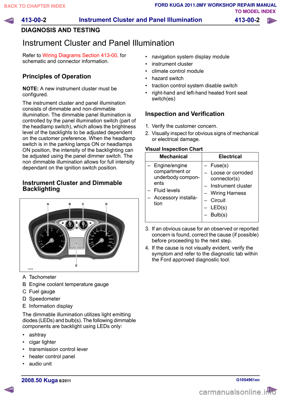
Instrument Cluster and Dimmable
Backlighting A.
Tachometer
B. Engine coolant temperature gauge
C. Fuel gauge
D. Speedometer
E. Information display
The dimmable illumination utilizes light emitting
diodes (LEDs) and bulb(s). The following dimmable
components are backlight using LEDs only:
• ashtray
• cigar lighter
• transmission control lever
• heater control panel
• audio unit • navigation system display module
• instrument cluster
• climate control module
• hazard switch
• traction control system disable switch
• right-hand and left-hand heated front seat
switch(es)
Inspection and Verification
1. Verify the customer concern.
2. Visually inspect for obvious signs of mechanical
or electrical damage.
Visual Inspection Chart Electrical
Mechanical
– Fuse(s)
– Loose or corrodedconnector(s)
– Instrument cluster
– Wiring Harness
– Circuit
– LED(s)
– Bulb(s)
– Engine/engine
compartment or
underbody compon-
ents
– Fluid levels
– Accessory installa- tion
3. If an obvious cause for an observed or reported concern is found, correct the cause (if possible)
before proceeding to the next step.
4. If the cause is not visually evident, verify the symptom and refer to the diagnostic tab within
the Ford approved diagnostic tool. G1054961en
2008.50 Kuga 8/2011 413-00-2
Instrument Cluster and Panel Illumination
413-00-2
DIAGNOSIS AND TESTINGTO MODEL INDEX
BACK TO CHAPTER INDEX
FORD KUGA 2011.0MY WORKSHOP REPAIR MANUALE98738ABCED
Page 187 of 2057
Description
Item
Instrument Cluster
1
PCM (powertrain control module)
2
EHPS (electro-hydraulic power steering)
control module
3
Audio unit
4
GEM (generic electronic module)
5
RCM (restraints control module)
6
PATS transceiver
7 Description
Item
Steering wheel lock module
8
Left-hand steering column switch
9
Fuel level sensor
10
Washer water level warning lamp switch
11
Accelerator pedal position sensor
12
CPP (clutch pedal position) sensor/BPP
(brake pedal position) sensor
13
Lighting control switch
14
System Operation
Instrument Cluster
The instrument cluster contains analog displays
as well as warning and control lamps for displaying
the system status; in addiiton, there is an LCD
indicator field for driver information.
The instrument cluster receives the following
signals from the PCM via the high speed CAN
(controller area network) Bus (HS-CAN):
• Vehicle speed – The PCM receives the necessary signalsfrom the ABS (anti-lock brake system) wheel
sensors from the ABS control unit on the
HS-CAN.
• Engine Coolant Temperature
• Engine oil pressure.
• Engine speed
The instrument cluster receives the following
signals from the GEM via the medium speed CAN
Bus (MS-CAN):
• Ambient temperature
• Brake fluid level
• Handbrake control
• Door latch control
• Liftgate latch control
• High beam control
• Headlamp flasher control
• Direction indicator control
The fuel level signal is sent by the two fuel level
sensors in the fuel pumps in the semitrailer tank,
which is wired to the instrument cluster. The
sensors are connected in series, and the total
resistance is determined from the two individual resistors. The instrument cluster converts the raw
fuel level signal into a damped fuel level value.
The odometer shows the total distance travelled
by the vehicle and is based on the same signal as
is processed for the daily mileage counter. The
value is recorded by the instrument cluster and
stored in a protected EEPROM (Electronically
Erasable Programmable Read Only Memory) area.
This area is a memory protected against
manipulation. If the instrument cluster detects an
error in this memory area, e.g. through damage,
the driver is notified with the "Odometer error"
message.
Message center
The message center is operated using the left-hand
switch on the steering column.
The SET/RESET button is activated to select a
submenu and change the settings. If signal tones
have been activated, a short acoustic signal will
sound each time a button is pressed.
By turning the rotary switch, the different menu
displays can be scrolled through or a setting
selected.
In this display, the navigation system can also
display direction and distance information.
In addition, safety and warning messages can be
displayed in this system, such as "Coolant
overheating", "Engine system error" or "Washer
fluid level too low". In addition to a safety message,
a general warning light (red/yellow) lights up.
G1030770en
2008.50 Kuga 8/2011 413-01-4
Instrument Cluster
413-01-4
DESCRIPTION AND OPERATIONTO MODEL INDEX
BACK TO CHAPTER INDEX
FORD KUGA 2011.0MY WORKSHOP REPAIR MANUAL