panel FORD KUGA 2011 1.G User Guide
[x] Cancel search | Manufacturer: FORD, Model Year: 2011, Model line: KUGA, Model: FORD KUGA 2011 1.GPages: 2057
Page 110 of 2057
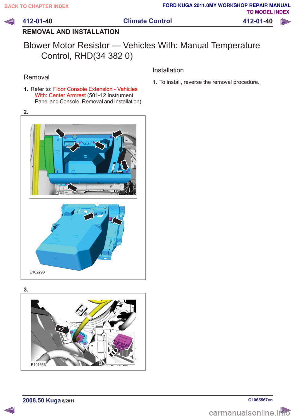
Blower Motor Resistor — Vehicles With: Manual TemperatureControl, RHD(34 382 0)
Removal
1.Refer to: Floor Console Extension - Vehicles
With: Center Armrest (501-12 Instrument
Panel and Console, Removal and Installation).
2.
E102293
3.
E101666
x2
Installation
1. To install, reverse the removal procedure.
G1065567en2008.50 Kuga8/2011
412-01- 40
Climate Control
412-01- 40
REMOVAL AND INSTALLATION
TO MODEL INDEX
BACK TO CHAPTER INDEX
FORD KUGA 2011.0MY WORKSHOP REPAIR MANUAL
Page 111 of 2057
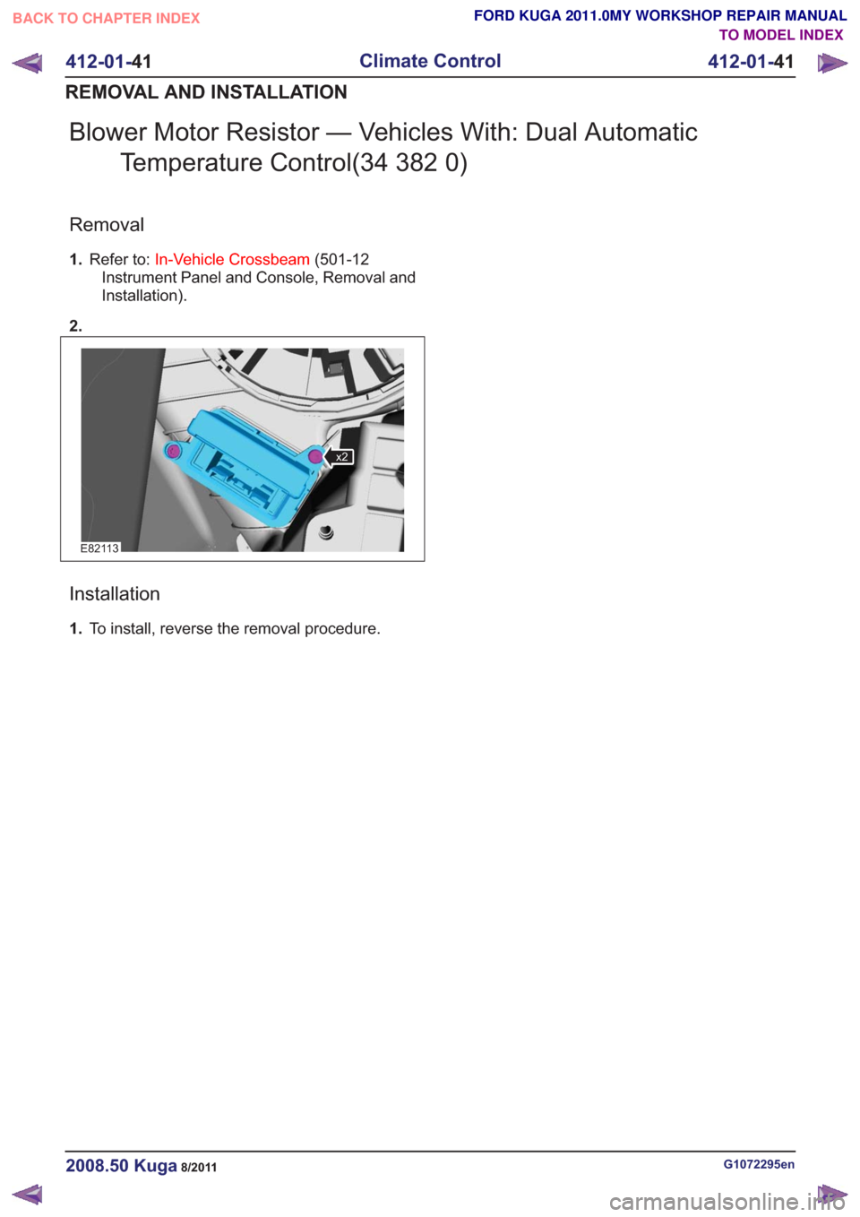
Blower Motor Resistor — Vehicles With: Dual AutomaticTemperature Control(34 382 0)
Removal
1.Refer to: In-Vehicle Crossbeam (501-12
Instrument Panel and Console, Removal and
Installation).
2.
E82113
x2
Installation
1. To install, reverse the removal procedure.
G1072295en2008.50 Kuga8/2011
412-01- 41
Climate Control
412-01- 41
REMOVAL AND INSTALLATION
TO MODEL INDEX
BACK TO CHAPTER INDEX
FORD KUGA 2011.0MY WORKSHOP REPAIR MANUAL
Page 135 of 2057
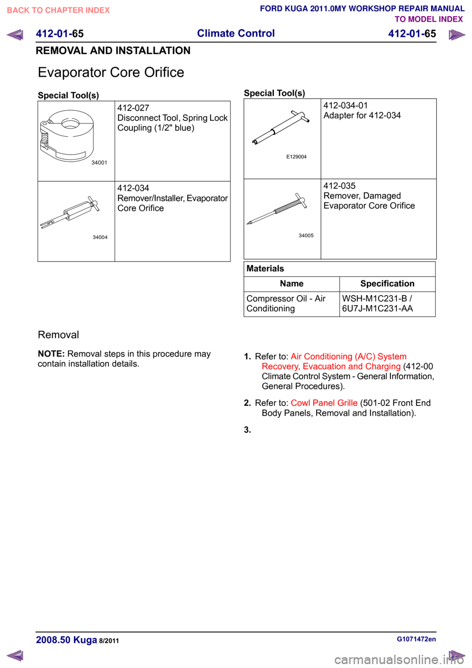
Evaporator Core Orifice
Special Tool(s)
412-027
Disconnect Tool, Spring Lock
Coupling (1/2" blue) 412-034
Remover/Installer, Evaporator
Core Orifice Special Tool(s)
412-034-01
Adapter for 412-034 412-035
Remover, Damaged
Evaporator Core Orifice
Materials
Specification
Name
WSH-M1C231-B /
6U7J-M1C231-AA
Compressor Oil - Air
Conditioning
Removal
NOTE: Removal steps in this procedure may
contain installation details. 1.
Refer to: Air Conditioning (A/C) System
Recovery, Evacuation and Charging (412-00
Climate Control System - General Information,
General Procedures).
2. Refer to: Cowl Panel Grille (501-02 Front End
Body Panels, Removal and Installation).
3. G1071472en
2008.50 Kuga 8/2011 412-01-65
Climate Control
412-01-65
REMOVAL AND INSTALLATIONTO MODEL INDEX
BACK TO CHAPTER INDEX
FORD KUGA 2011.0MY WORKSHOP REPAIR MANUAL34001 34004 E129004 34005
Page 148 of 2057
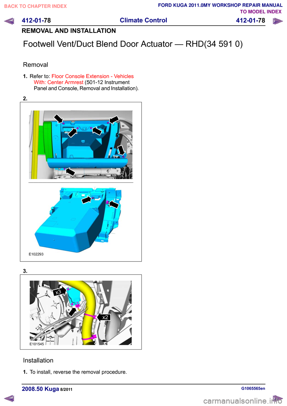
Footwell Vent/Duct Blend Door Actuator — RHD(34 591 0)
Removal
1.
Refer to: Floor Console Extension - Vehicles
With: Center Armrest (501-12 Instrument
Panel and Console, Removal and Installation).
2. 3.
Installation
1.
To install, reverse the removal procedure. G1065565en
2008.50 Kuga 8/2011 412-01-78
Climate Control
412-01-78
REMOVAL AND INSTALLATIONTO MODEL INDEX
BACK TO CHAPTER INDEX
FORD KUGA 2011.0MY WORKSHOP REPAIR MANUALE102293 E101545x2x3
Page 149 of 2057
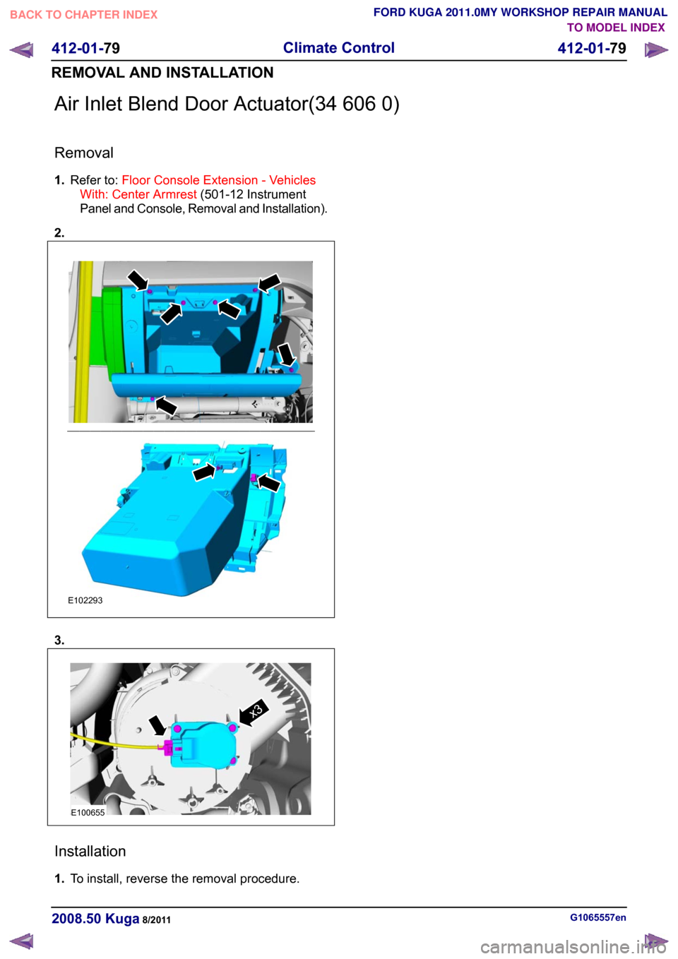
Air Inlet Blend Door Actuator(34 606 0)
Removal
1.
Refer to: Floor Console Extension - Vehicles
With: Center Armrest (501-12 Instrument
Panel and Console, Removal and Installation).
2. 3.
Installation
1.
To install, reverse the removal procedure. G1065557en
2008.50 Kuga 8/2011 412-01-79
Climate Control
412-01-79
REMOVAL AND INSTALLATIONTO MODEL INDEX
BACK TO CHAPTER INDEX
FORD KUGA 2011.0MY WORKSHOP REPAIR MANUALE102293 E100655x3
Page 171 of 2057
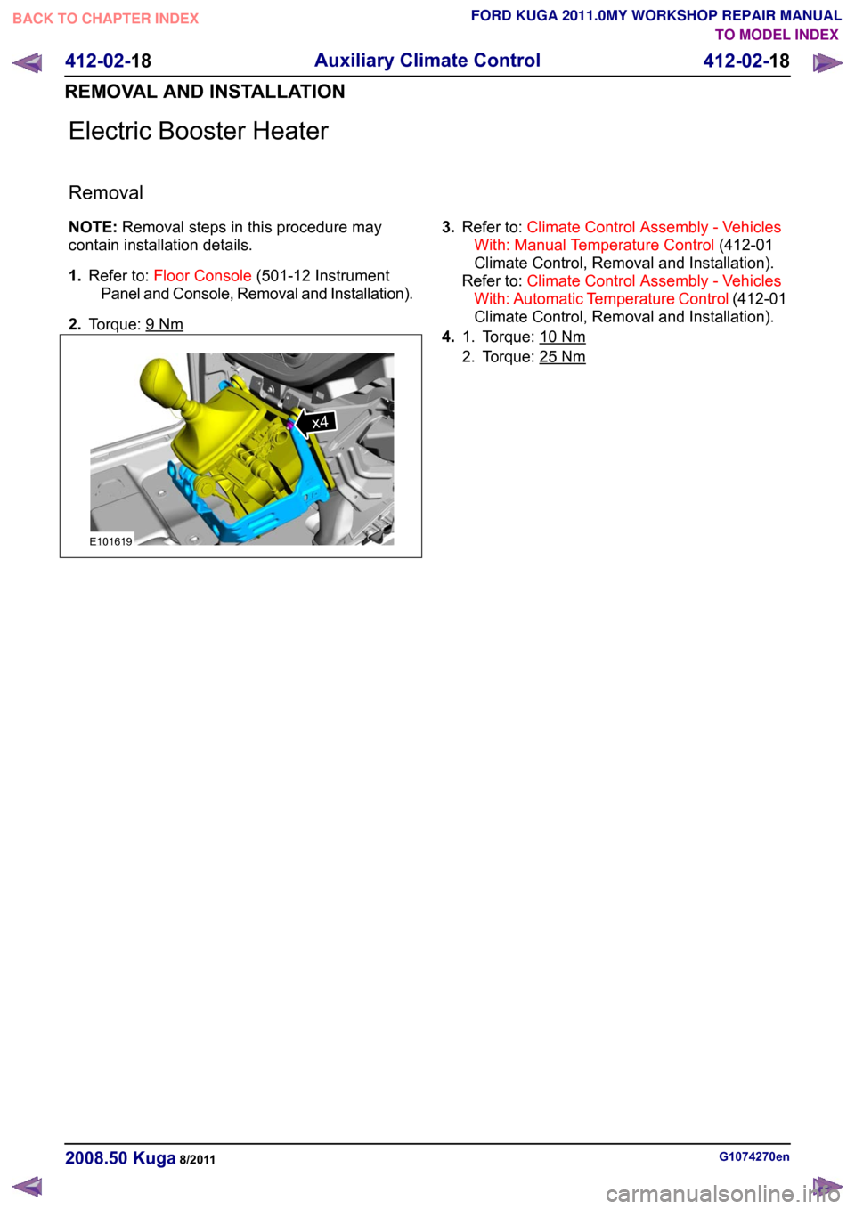
Electric Booster Heater
Removal
NOTE:
Removal steps in this procedure may
contain installation details.
1. Refer to: Floor Console (501-12 Instrument
Panel and Console, Removal and Installation).
2. Torque: 9 Nm 3.
Refer to: Climate Control Assembly - Vehicles
With: Manual Temperature Control (412-01
Climate Control, Removal and Installation).
Refer to: Climate Control Assembly - Vehicles
With: Automatic Temperature Control (412-01
Climate Control, Removal and Installation).
4. Torque: 10 Nm1.
2. Torque: 25
Nm
G1074270en
2008.50 Kuga 8/2011 412-02-18
Auxiliary Climate Control
412-02-18
REMOVAL AND INSTALLATIONTO MODEL INDEX
BACK TO CHAPTER INDEX
FORD KUGA 2011.0MY WORKSHOP REPAIR MANUALx4E101619
Page 182 of 2057
SECTION 413-00 Instrument Cluster and Panel
Illumination
VEHICLE APPLICATION:
2008.50 Kuga
PAGE
CONTENTS
DIAGNOSIS AND TESTING
413-00-2
Instrument Cluster and Panel Illumination..........................................................................
413-00-2
Principles of Operation.......................................................................................................
413-00-2
Instrument Cluster and Dimmable Backlighting ................................................................
413-00-2
Inspection and Verification.................................................................................................. 413-00-1
Instrument Cluster and Panel Illumination
413-00-1
.TO MODEL INDEX
BACK TO CHAPTER INDEX
FORD KUGA 2011.0MY WORKSHOP REPAIR MANUAL
Page 183 of 2057
Instrument Cluster and Panel Illumination
Refer to
Wiring Diagrams Section 413-00, for
schematic and connector information.
Principles of Operation
NOTE: A new instrument cluster must be
configured.
The instrument cluster and panel illumination
consists of dimmable and non-dimmable
illumination. The dimmable panel illumination is
controlled by the panel illumination switch (part of
the headlamp switch), which allows the brightness
level of the backlights to be adjusted dependent
on the customer preference. When the headlamp
switch is in the parking lamps ON or headlamps
ON position, the intensity of the backlighting can
be adjusted using the panel dimmer switch. The
non dimmable illumination allows for full intensity
dependant on the ignition switch position.
Instrument Cluster and Dimmable
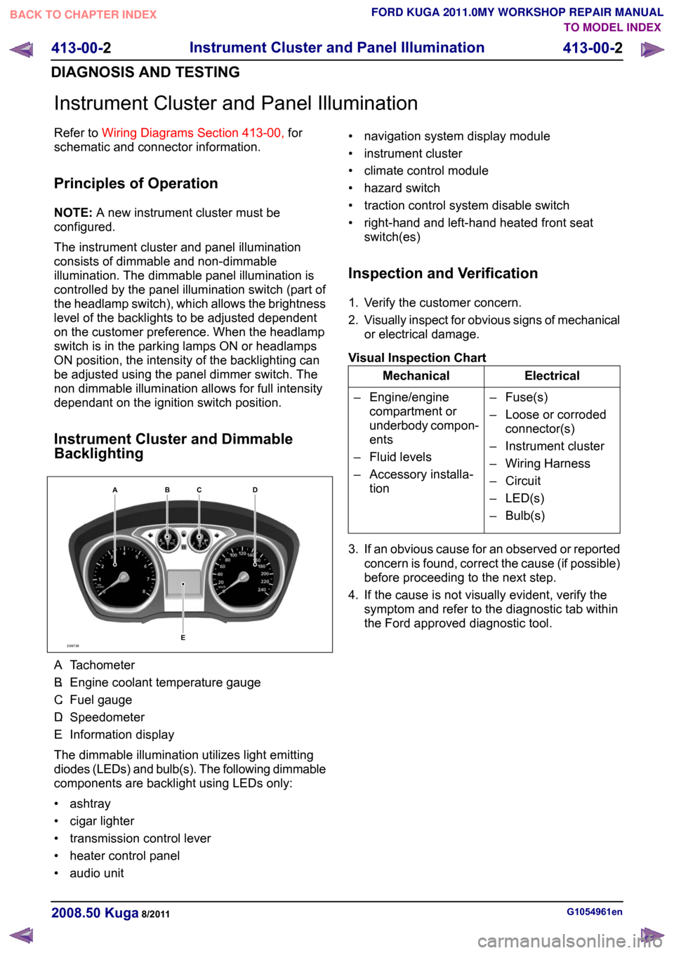
Backlighting A.
Tachometer
B. Engine coolant temperature gauge
C. Fuel gauge
D. Speedometer
E. Information display
The dimmable illumination utilizes light emitting
diodes (LEDs) and bulb(s). The following dimmable
components are backlight using LEDs only:
• ashtray
• cigar lighter
• transmission control lever
• heater control panel
• audio unit • navigation system display module
• instrument cluster
• climate control module
• hazard switch
• traction control system disable switch
• right-hand and left-hand heated front seat
switch(es)
Inspection and Verification
1. Verify the customer concern.
2. Visually inspect for obvious signs of mechanical
or electrical damage.
Visual Inspection Chart Electrical
Mechanical
– Fuse(s)
– Loose or corrodedconnector(s)
– Instrument cluster
– Wiring Harness
– Circuit
– LED(s)
– Bulb(s)
– Engine/engine
compartment or
underbody compon-
ents
– Fluid levels
– Accessory installa- tion
3. If an obvious cause for an observed or reported concern is found, correct the cause (if possible)
before proceeding to the next step.
4. If the cause is not visually evident, verify the symptom and refer to the diagnostic tab within
the Ford approved diagnostic tool. G1054961en
2008.50 Kuga 8/2011 413-00-2
Instrument Cluster and Panel Illumination
413-00-2
DIAGNOSIS AND TESTINGTO MODEL INDEX
BACK TO CHAPTER INDEX
FORD KUGA 2011.0MY WORKSHOP REPAIR MANUALE98738ABCED
Page 243 of 2057
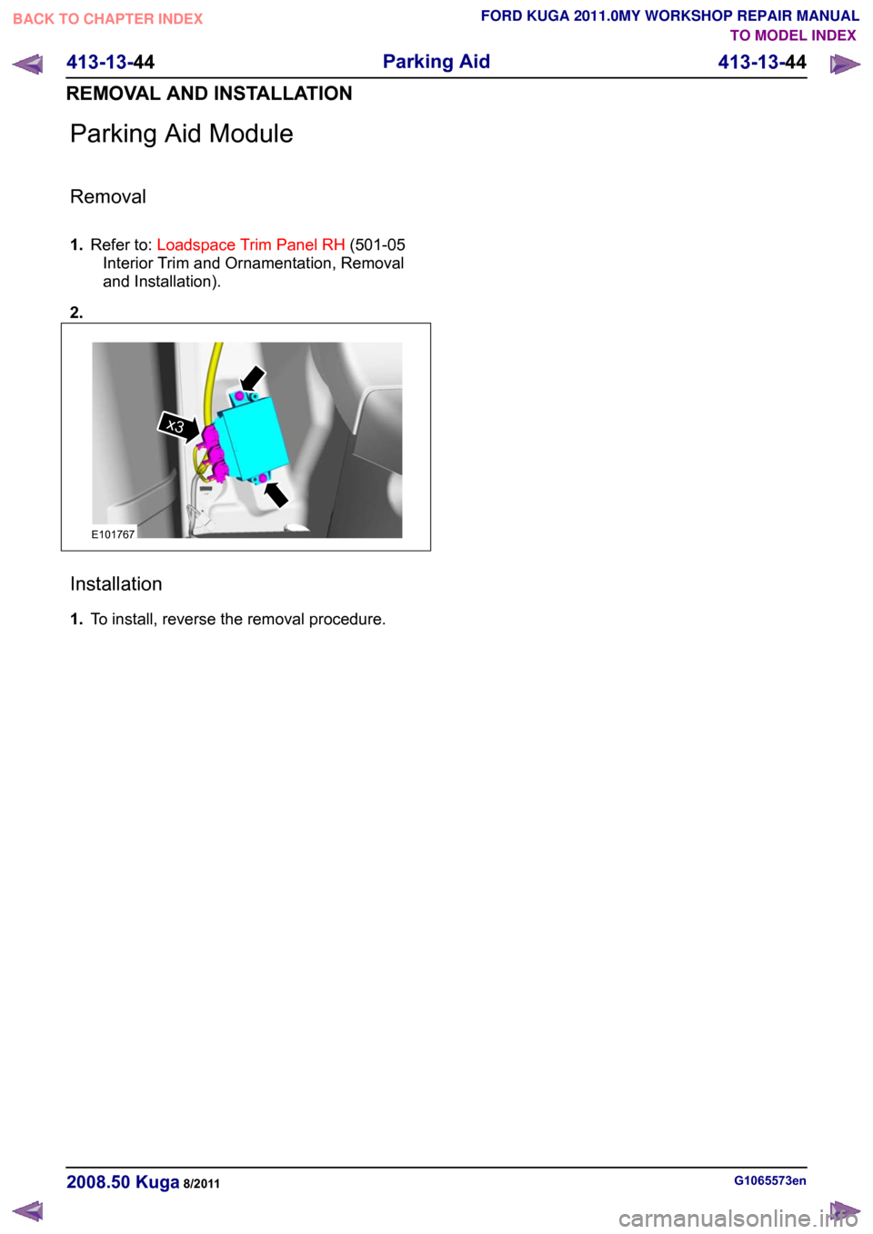
Parking Aid Module
Removal
1.
Refer to: Loadspace Trim Panel RH (501-05
Interior Trim and Ornamentation, Removal
and Installation).
2. Installation
1.
To install, reverse the removal procedure. G1065573en
2008.50 Kuga 8/2011 413-13-44
Parking Aid
413-13-44
REMOVAL AND INSTALLATIONTO MODEL INDEX
BACK TO CHAPTER INDEX
FORD KUGA 2011.0MY WORKSHOP REPAIR MANUALx3E101767
Page 244 of 2057
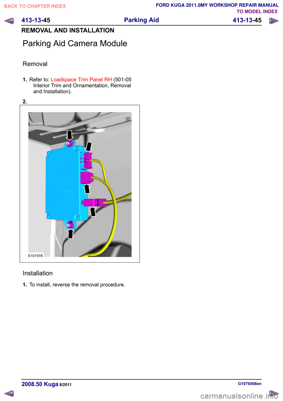
Parking Aid Camera Module
Removal
1.
Refer to: Loadspace Trim Panel RH (501-05
Interior Trim and Ornamentation, Removal
and Installation).
2. Installation
1.
To install, reverse the removal procedure. G1076568en
2008.50 Kuga 8/2011 413-13-45
Parking Aid
413-13-45
REMOVAL AND INSTALLATIONTO MODEL INDEX
BACK TO CHAPTER INDEX
FORD KUGA 2011.0MY WORKSHOP REPAIR MANUALE101978