panel FORD KUGA 2011 1.G Owner's Manual
[x] Cancel search | Manufacturer: FORD, Model Year: 2011, Model line: KUGA, Model: FORD KUGA 2011 1.GPages: 2057
Page 267 of 2057
Action
Battery Tester Reading WARNING: Do not recharge the battery.
Make sure that the surface charge was removed. A "REPLACE BATTERY" result could also mean
a poor connection between the battery cables and the battery. Check the connections are OK and
retest. If the result remains the same, INSTALL a NEW battery
REFER to: Battery(414-01 Battery, Mounting and
Cables, Removal and Installation).
REPLACE BATTERY or BAD CELL BATTERY
In addition it is advisable to check the vehicle electrical system. Check that the generator is functioning
correctly and the vehicle does not have an excessive key-off load (in general this should be under
20mA after 40 minutes of key off).
Midtronics EXP-1050 Battery Tester Test
Code
At the end of the test, use the arrow keys to scroll
down the screens to see additional information.
One of these is the TEST CODE.
The TEST CODE has 11 digits, for example:
0021U-B88WKX.
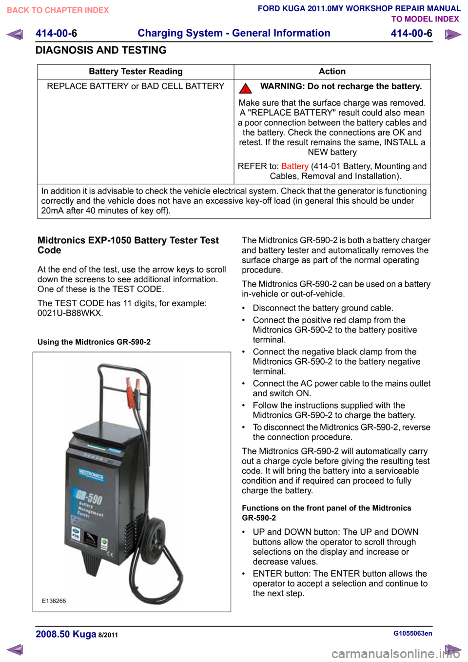
Using the Midtronics GR-590-2 The Midtronics GR-590-2 is both a battery charger
and battery tester and automatically removes the
surface charge as part of the normal operating
procedure.
The Midtronics GR-590-2 can be used on a battery
in-vehicle or out-of-vehicle.
• Disconnect the battery ground cable.
• Connect the positive red clamp from the
Midtronics GR-590-2 to the battery positive
terminal.
• Connect the negative black clamp from the Midtronics GR-590-2 to the battery negative
terminal.
• Connect the AC power cable to the mains outlet
and switch ON.
• Follow the instructions supplied with the Midtronics GR-590-2 to charge the battery.
• To disconnect the Midtronics GR-590-2, reverse
the connection procedure.
The Midtronics GR-590-2 will automatically carry
out a charge cycle before giving the resulting test
code. It will bring the battery into a serviceable
condition and if required can proceed to fully
charge the battery.
Functions on the front panel of the Midtronics
GR-590-2
• UP and DOWN button: The UP and DOWN buttons allow the operator to scroll through
selections on the display and increase or
decrease values.
• ENTER button: The ENTER button allows the operator to accept a selection and continue to
the next step. G1055063en
2008.50 Kuga 8/2011 414-00-6
Charging System - General Information
414-00-6
DIAGNOSIS AND TESTINGTO MODEL INDEX
BACK TO CHAPTER INDEX
FORD KUGA 2011.0MY WORKSHOP REPAIR MANUALE136266
Page 283 of 2057
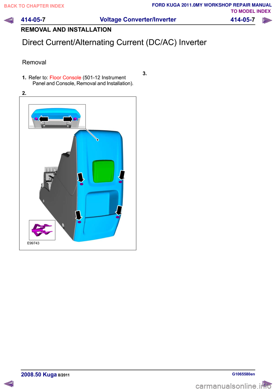
Direct Current/Alternating Current (DC/AC) Inverter
Removal
1.
Refer to: Floor Console (501-12 Instrument
Panel and Console, Removal and Installation).
2. 3.
G1065580en
2008.50 Kuga 8/2011 414-05-7
Voltage Converter/Inverter
414-05-7
REMOVAL AND INSTALLATIONTO MODEL INDEX
BACK TO CHAPTER INDEX
FORD KUGA 2011.0MY WORKSHOP REPAIR MANUALE99743
Page 297 of 2057

SECTION 415-01 Information and Entertainment
System
VEHICLE APPLICATION:
2008.50 Kuga
PAGE
CONTENTS
DESCRIPTION AND OPERATION
415-01-2
Audio System (Component Location).................................................................................
415-01-3
Audio System (Overview)...................................................................................................
415-01-3
Keycode entry - vehicle with standard audio system.........................................................
415-01-3
Vehicle Identification Number (VID) - entry - vehicle with standard audio system.............
415-01-3
Self-check routine - vehicles with standard audio system..................................................
415-01-3
Keycode entry - vehicles with upgraded audio system......................................................
415-01-5
Audio System (System Operation and Component Description)........................................
415-01-5
System Diagram.................................................................................................................
415-01-8
System Operation...............................................................................................................
415-01-8
In-car entertainment........................................................................................................
415-01-8
Component Description......................................................................................................
415-01-8
Vehicles with standard audio system..............................................................................
415-01-9
Vehicles with upgraded audio system.............................................................................
415-01-9
DAB radio........................................................................................................................
415-01-9
AUX port.........................................................................................................................
415-01-9
Radio remote control......................................................................................................415-01-10Antenna systems............................................................................................................
415-01-11
Cellular Phone (Component Location)...............................................................................
415-01-12
Cellular Phone (Overview)..................................................................................................
415-01-12
Software update - control module for mobile electronic auxiliary equipment (variant 1)....
415-01-12
Software update - control module for mobile electronic auxiliary equipment (variants 2
and 3)................................................................................................................................ 415-01-13
Cellular Phone (System Operation and Component Description)......................................
415-01-13
System Diagram.................................................................................................................
415-01-17
System Operation...............................................................................................................
415-01-17
Overview .........................................................................................................................
415-01-17
Voice Control...................................................................................................................
415-01-18
Component Description......................................................................................................
415-01-18Control module for mobile electronic auxiliary equipment..............................................
415-01-19Radio remote control......................................................................................................
415-01-19USB port/AUX socket.....................................................................................................
REMOVAL AND INSTALLATION 415-01-20
Audio Unit...........................................................................................................................
415-01-21
Audio Unit Antenna — Vehicles With: Glass Roof Panel...................................................
415-01-22
Audio Unit Antenna — Vehicles Without: Glass Roof Panel..............................................
415-01-23
Audio Unit Antenna to Connector Cable — Vehicles With: Glass Roof Panel...................
415-01-30
Audio Unit Antenna to Connector Cable — Vehicles Without: Glass Roof Panel..............
415-01-32
Connector to Audio Unit Antenna Cable.............................................................................
415-01-35
Compact Disc (CD) Changer..............................................................................................
415-01-37
(33 635 0)
Portable Support Electronics (PSE) Module..................................................
415-01-38
Cellular Phone Microphone................................................................................................ 415-01-1
Information and Entertainment System
415-01-1
.
TO MODEL INDEX
BACK TO CHAPTER INDEX
FORD KUGA 2011.0MY WORKSHOP REPAIR MANUAL
Page 317 of 2057
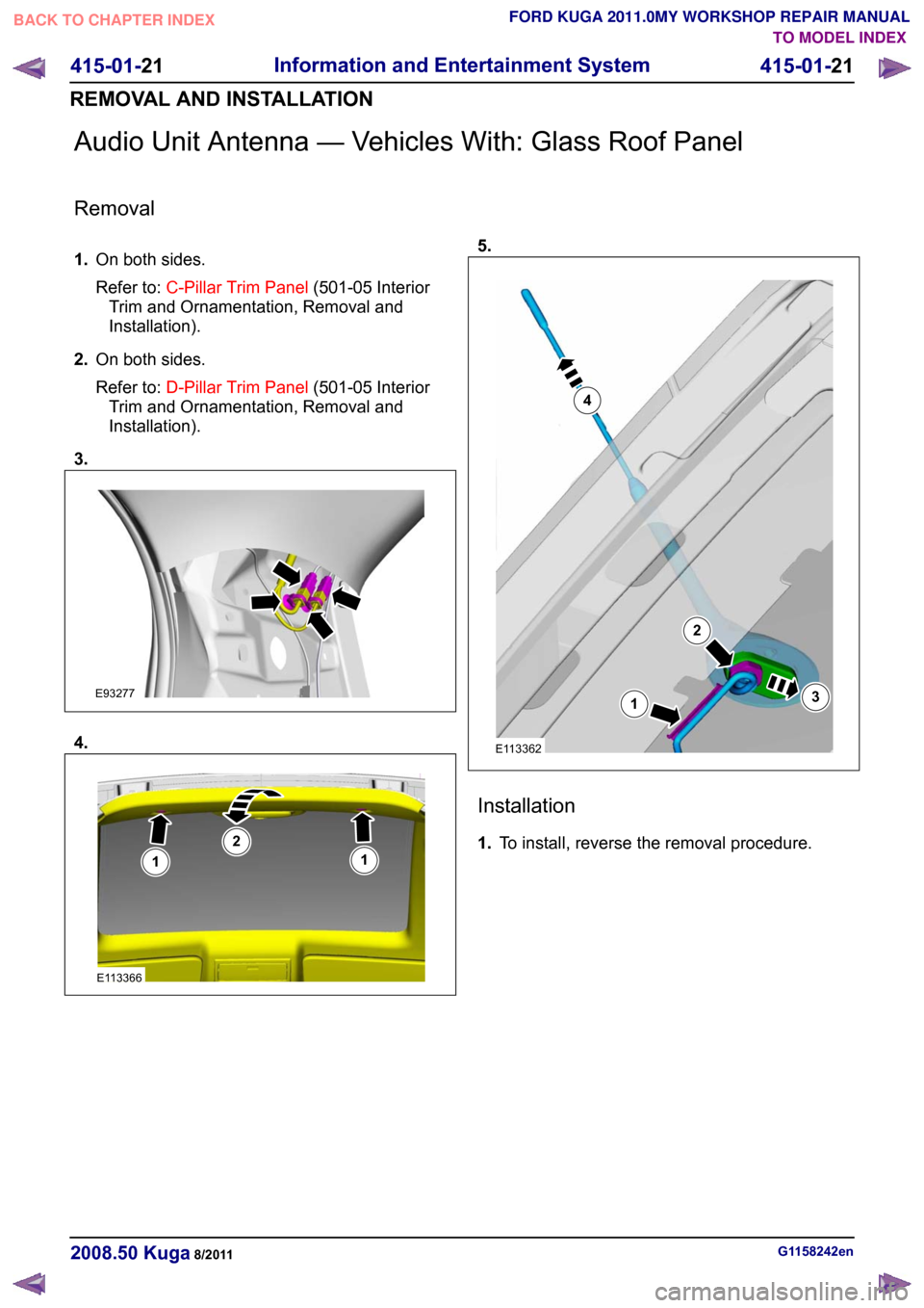
Audio Unit Antenna — Vehicles With: Glass Roof Panel
Removal
1.
On both sides.
Refer to: C-Pillar Trim Panel (501-05 Interior
Trim and Ornamentation, Removal and
Installation).
2. On both sides.
Refer to: D-Pillar Trim Panel (501-05 Interior
Trim and Ornamentation, Removal and
Installation).
3. 4. 5.
Installation
1.
To install, reverse the removal procedure. G1158242en
2008.50 Kuga 8/2011 415-01-21
Information and Entertainment System
415-01-21
REMOVAL AND INSTALLATIONTO MODEL INDEX
BACK TO CHAPTER INDEX
FORD KUGA 2011.0MY WORKSHOP REPAIR MANUALE93277 E113366112 E1133621234
Page 318 of 2057
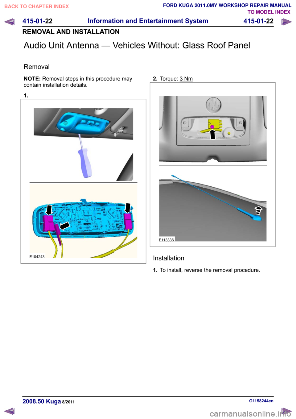
Audio Unit Antenna — Vehicles Without: Glass Roof Panel
Removal
NOTE:
Removal steps in this procedure may
contain installation details.
1. 2.
Torque: 3 Nm
Installation
1.
To install, reverse the removal procedure. G1158244en
2008.50 Kuga 8/2011 415-01-22
Information and Entertainment System
415-01-22
REMOVAL AND INSTALLATIONTO MODEL INDEX
BACK TO CHAPTER INDEX
FORD KUGA 2011.0MY WORKSHOP REPAIR MANUALE104243 E113336
Page 319 of 2057
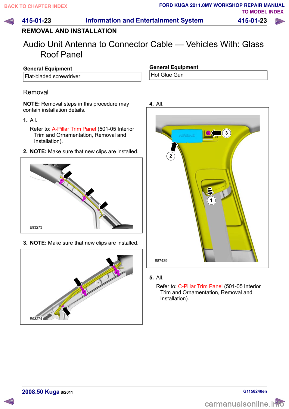
Audio Unit Antenna to Connector Cable — Vehicles With: Glass
Roof Panel General Equipment
Flat-bladed screwdriver General Equipment
Hot Glue Gun
Removal
NOTE: Removal steps in this procedure may
contain installation details.
1. All.
Refer to: A-Pillar Trim Panel (501-05 Interior
Trim and Ornamentation, Removal and
Installation).
2. NOTE: Make sure that new clips are installed.3. NOTE:
Make sure that new clips are installed. 4.
All. 5.
All.
Refer to: C-Pillar Trim Panel (501-05 Interior
Trim and Ornamentation, Removal and
Installation). G1158248en
2008.50 Kuga 8/2011 415-01-23
Information and Entertainment System
415-01-23
REMOVAL AND INSTALLATIONTO MODEL INDEX
BACK TO CHAPTER INDEX
FORD KUGA 2011.0MY WORKSHOP REPAIR MANUALE93273 E93274 123E87439
Page 326 of 2057
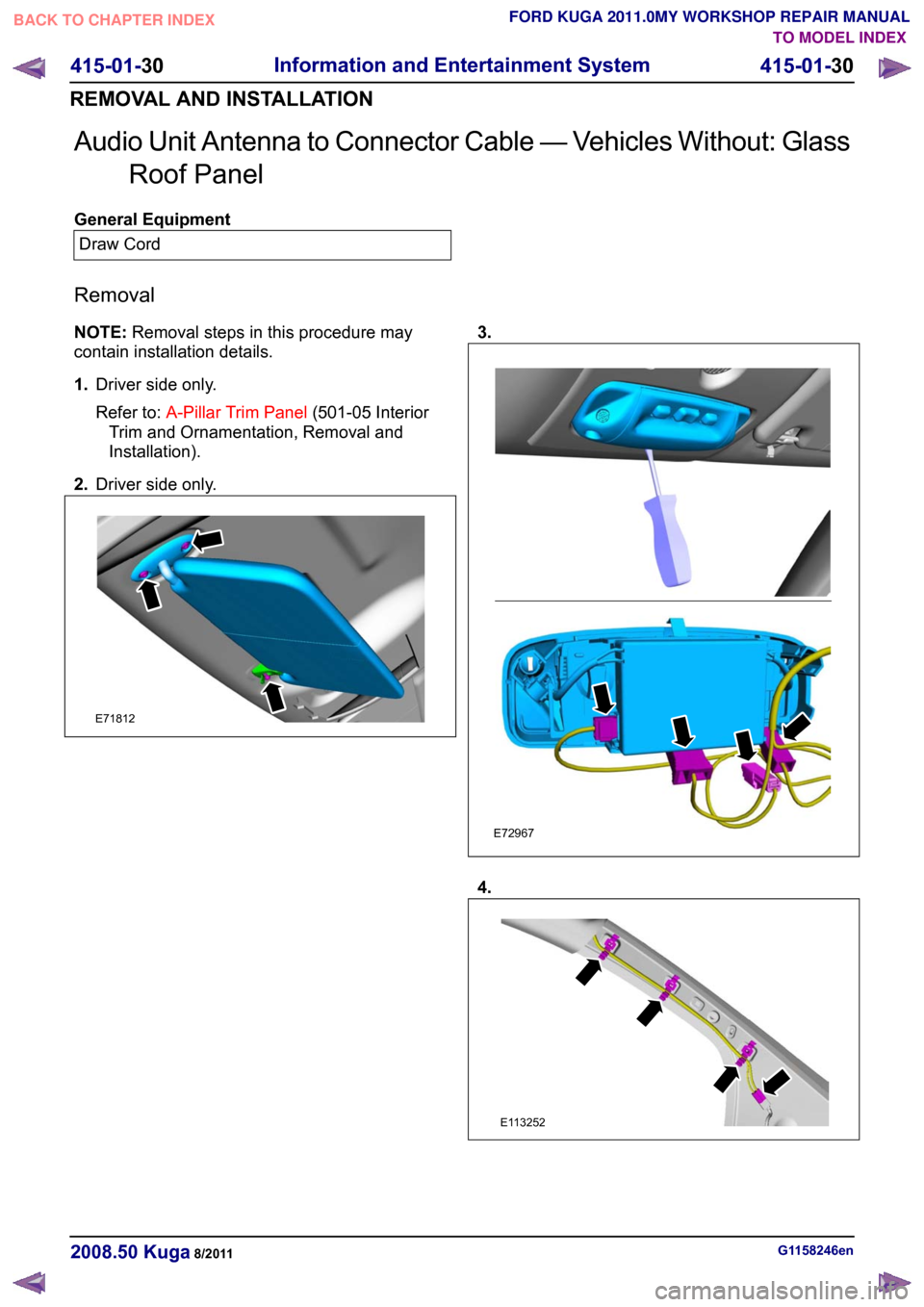
Audio Unit Antenna to Connector Cable — Vehicles Without: Glass
Roof Panel General Equipment
Draw Cord
Removal
NOTE: Removal steps in this procedure may
contain installation details.
1. Driver side only.
Refer to: A-Pillar Trim Panel (501-05 Interior
Trim and Ornamentation, Removal and
Installation).
2. Driver side only. 3.
4.
G1158246en
2008.50 Kuga 8/2011 415-01-30
Information and Entertainment System
415-01-30
REMOVAL AND INSTALLATIONTO MODEL INDEX
BACK TO CHAPTER INDEX
FORD KUGA 2011.0MY WORKSHOP REPAIR MANUALE71812 E72967 E113252
Page 333 of 2057
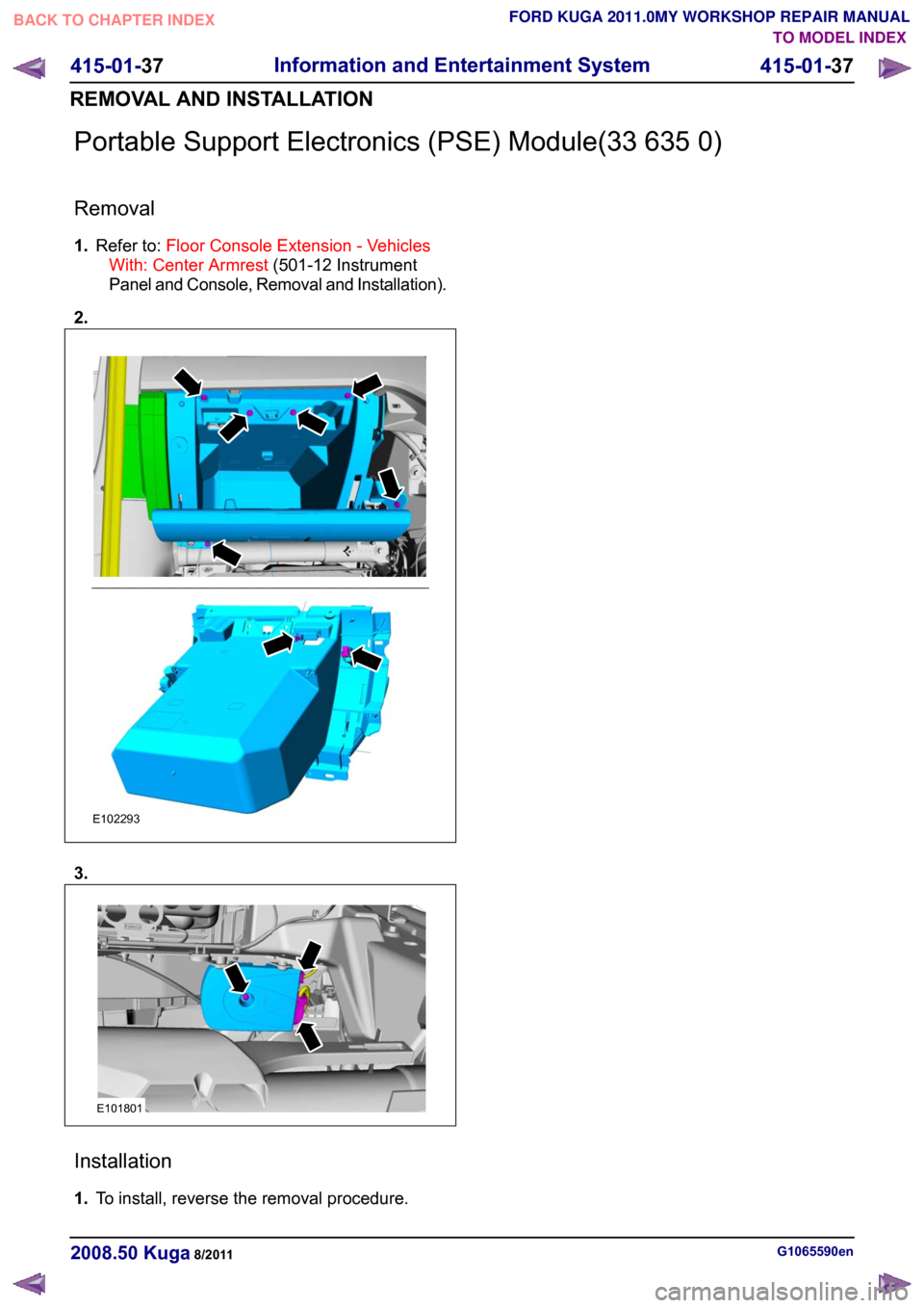
Portable Support Electronics (PSE) Module(33 635 0)
Removal
1.
Refer to: Floor Console Extension - Vehicles
With: Center Armrest (501-12 Instrument
Panel and Console, Removal and Installation).
2. 3.
Installation
1.
To install, reverse the removal procedure. G1065590en
2008.50 Kuga 8/2011 415-01-37
Information and Entertainment System
415-01-37
REMOVAL AND INSTALLATIONTO MODEL INDEX
BACK TO CHAPTER INDEX
FORD KUGA 2011.0MY WORKSHOP REPAIR MANUALE102293 E101801
Page 341 of 2057
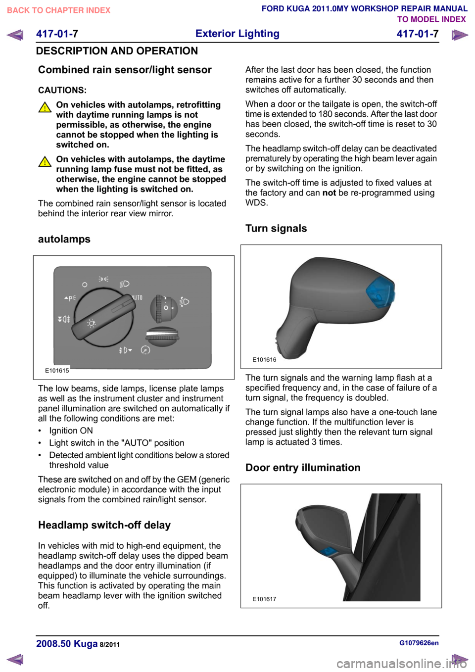
Combined rain sensor/light sensor
CAUTIONS:
On vehicles with autolamps, retrofitting
with daytime running lamps is not
permissible, as otherwise, the engine
cannot be stopped when the lighting is
switched on.
On vehicles with autolamps, the daytime
running lamp fuse must not be fitted, as
otherwise, the engine cannot be stopped
when the lighting is switched on.
The combined rain sensor/light sensor is located
behind the interior rear view mirror.
autolamps The low beams, side lamps, license plate lamps
as well as the instrument cluster and instrument
panel illumination are switched on automatically if
all the following conditions are met:
• Ignition ON
• Light switch in the "AUTO" position
•
Detected ambient light conditions below a stored
threshold value
These are switched on and off by the GEM (generic
electronic module) in accordance with the input
signals from the combined rain/light sensor.
Headlamp switch-off delay
In vehicles with mid to high-end equipment, the
headlamp switch-off delay uses the dipped beam
headlamps and the door entry illumination (if
equipped) to illuminate the vehicle surroundings.
This function is activated by operating the main
beam headlamp lever with the ignition switched
off. After the last door has been closed, the function
remains active for a further 30 seconds and then
switches off automatically.
When a door or the tailgate is open, the switch-off
time is extended to 180 seconds. After the last door
has been closed, the switch-off time is reset to 30
seconds.
The headlamp switch-off delay can be deactivated
prematurely by operating the high beam lever again
or by switching on the ignition.
The switch-off time is adjusted to fixed values at
the factory and can
notbe re-programmed using
WDS.
Turn signals The turn signals and the warning lamp flash at a
specified frequency and, in the case of failure of a
turn signal, the frequency is doubled.
The turn signal lamps also have a one-touch lane
change function. If the multifunction lever is
pressed just slightly then the relevant turn signal
lamp is actuated 3 times.
Door entry illumination
G1079626en
2008.50 Kuga 8/2011 417-01-7
Exterior Lighting
417-01-7
DESCRIPTION AND OPERATIONTO MODEL INDEX
BACK TO CHAPTER INDEX
FORD KUGA 2011.0MY WORKSHOP REPAIR MANUALE101615 E101616 E101617
Page 345 of 2057
The manual headlamp levelling system operates
with an electric motor which is controlled via a
rotary control in the instrument cluster.
Turn signals
The GEM switches the direction indicators and the
direction indicator side repeaters on.
The GEM sends a signal to the instrument cluster
via the CAN (controller area network) bus to switch
on the relevant turn indicator and the acoustic
signal.
The signals from the hazard flasher switch and
from the multifunction switch are transmitted to the
GEM via a wiring connection.
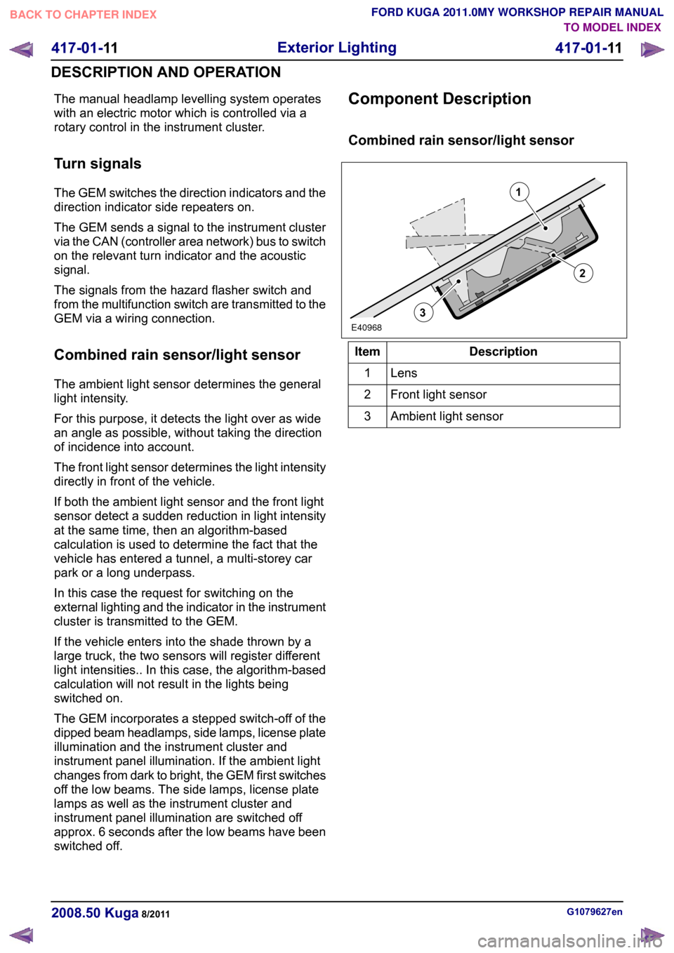
Combined rain sensor/light sensor
The ambient light sensor determines the general
light intensity.
For this purpose, it detects the light over as wide
an angle as possible, without taking the direction
of incidence into account.
The front light sensor determines the light intensity
directly in front of the vehicle.
If both the ambient light sensor and the front light
sensor detect a sudden reduction in light intensity
at the same time, then an algorithm-based
calculation is used to determine the fact that the
vehicle has entered a tunnel, a multi-storey car
park or a long underpass.
In this case the request for switching on the
external lighting and the indicator in the instrument
cluster is transmitted to the GEM.
If the vehicle enters into the shade thrown by a
large truck, the two sensors will register different
light intensities.. In this case, the algorithm-based
calculation will not result in the lights being
switched on.
The GEM incorporates a stepped switch-off of the
dipped beam headlamps, side lamps, license plate
illumination and the instrument cluster and
instrument panel illumination. If the ambient light
changes from dark to bright, the GEM first switches
off the low beams. The side lamps, license plate
lamps as well as the instrument cluster and
instrument panel illumination are switched off
approx. 6 seconds after the low beams have been
switched off.
Component Description
Combined rain sensor/light sensor
Description
Item
Lens1
Front light sensor
2
Ambient light sensor
3 G1079627en
2008.50 Kuga 8/2011 417-01-11
Exterior Lighting
417-01-11
DESCRIPTION AND OPERATIONTO MODEL INDEX
BACK TO CHAPTER INDEX
FORD KUGA 2011.0MY WORKSHOP REPAIR MANUAL213E40968