panel FORD KUGA 2011 1.G Service Manual
[x] Cancel search | Manufacturer: FORD, Model Year: 2011, Model line: KUGA, Model: FORD KUGA 2011 1.GPages: 2057
Page 1528 of 2057
TIE44583
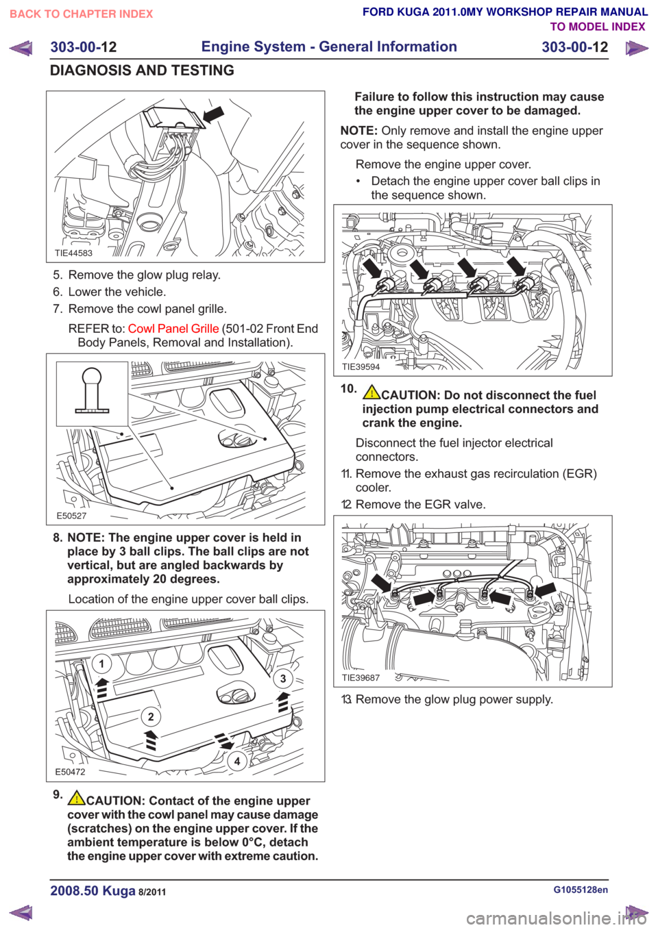
5. Remove the glow plug relay.
6. Lower the vehicle.
7. Remove the cowl panel grille.REFER to: Cowl Panel Grille (501-02 Front End
Body Panels, Removal and Installation).
E50527
8. NOTE: The engine upper cover is held in place by 3 ball clips. The ball clips are not
vertical, but are angled backwards by
approximately 20 degrees.
Location of the engine upper cover ball clips.
E50472
2
1
3
4
9.CAUTION: Contact of the engine upper
cover with the cowl panel may cause damage
(scratches) on the engine upper cover. If the
ambient temperature is below 0°C, detach
the engine upper cover with extreme caution. Failure to follow this instruction may cause
the engine upper cover to be damaged.
NOTE: Only remove and install the engine upper
cover in the sequence shown.
Remove the engine upper cover.• Detach the engine upper cover ball clips in the sequence shown.
TIE39594
10.CAUTION: Do not disconnect the fuel
injection pump electrical connectors and
crank the engine.
Disconnect the fuel injector electrical
connectors.
11. Remove the exhaust gas recirculation (EGR) cooler.
12. Remove the EGR valve.
TIE39687
13. Remove the glow plug power supply.
G1055128en2008.50 Kuga8/2011
303-00- 12
Engine System - General Information
303-00- 12
DIAGNOSIS AND TESTING
TO MODEL INDEX
BACK TO CHAPTER INDEX
FORD KUGA 2011.0MY WORKSHOP REPAIR MANUAL
Page 1529 of 2057
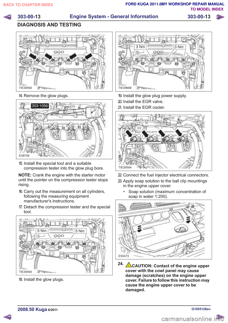
18. Install the glow plugs.
CAUTION: Contact of the engine upper
cover with the cowl panel may cause
damage (scratches) on the engine upper
cover. Failure to follow this instruction may
cause the engine upper cover to be
damaged.
G1055128en2008.50 Kuga8/2011
303-00- 13
Engine System - General Information
303-00- 13
DIAGNOSIS AND TESTING
FORD KUGA 2011.0MY WORKSHOP REPAIR MANUAL
TO MODEL INDEX
BACK TO CHAPTER INDEX
TIE39592TIE39688
E39706
303-1056
TIE39593
3Nm
TIE39594
E50473
3Nm
5Nm 5Nm
14. Remove the glow plugs.
15. Install the special tool and a suitable
compression tester into the glow plug bore.
NOTE: Crank the engine with the starter motor
until the pointer on the compression tester stops
rising.
16. Carry out the measurement on all cylinders, following the measuring equipment
manufacturer's instructions.
17. Detach the compression tester and the special tool.
19. Install the glow plug power supply.
20. Install the EGR valve.
21. Install the EGR cooler.
22. Connect the fuel injector electrical connectors.
23. Apply soap solution to the ball clip mountingsin the engine upper cover.
• Soap solution (maximum concentration of soap in water 1:200).
24.
Page 1530 of 2057
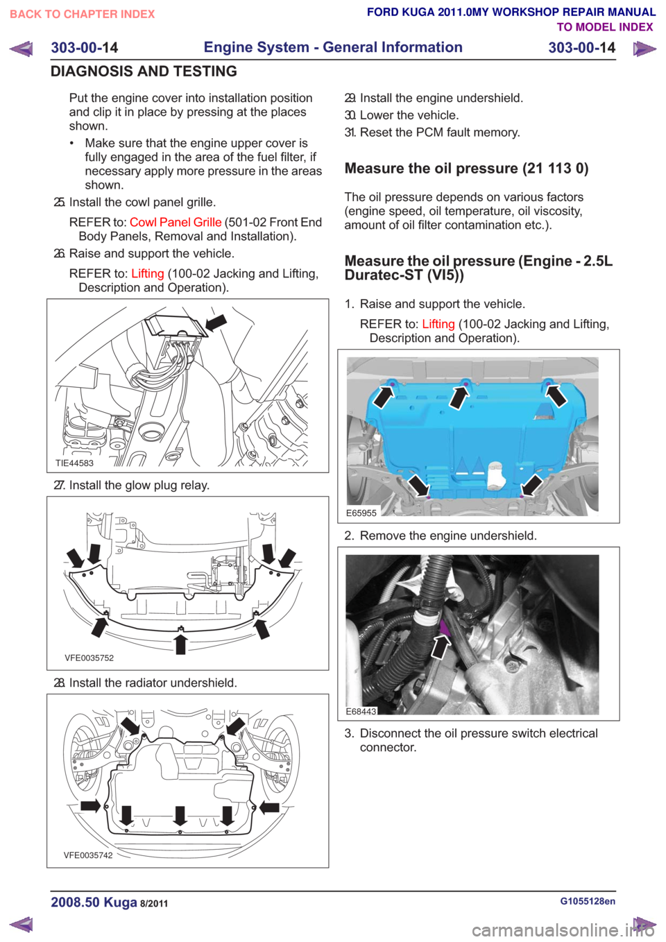
Put the engine cover into installation position
and clip it in place by pressing at the places
shown.• Make sure that the engine upper cover is fully engaged in the area of the fuel filter, if
necessary apply more pressure in the areas
shown.
25. Install the cowl panel grille.
REFER to: Cowl Panel Grille (501-02 Front End
Body Panels, Removal and Installation).
26. Raise and support the vehicle.
REFER to: Lifting(100-02 Jacking and Lifting,
Description and Operation).
TIE44583
27. Install the glow plug relay.
VFE0035752
28. Install the radiator undershield.
VFE0035742
29. Install the engine undershield.
30. Lower the vehicle.
31. Reset the PCM fault memory.
Measure the oil pressure (21 113 0)
The oil pressure depends on various factors
(engine speed, oil temperature, oil viscosity,
amount of oil filter contamination etc.).
Measure the oil pressure (Engine - 2.5L
Duratec-ST (VI5))
1. Raise and support the vehicle.
REFER to: Lifting(100-02 Jacking and Lifting,
Description and Operation).
E65955
2. Remove the engine undershield.
E68443
3. Disconnect the oil pressure switch electrical connector.
G1055128en2008.50 Kuga8/2011
303-00- 14
Engine System - General Information
303-00- 14
DIAGNOSIS AND TESTING
TO MODEL INDEX
BACK TO CHAPTER INDEX
FORD KUGA 2011.0MY WORKSHOP REPAIR MANUAL
Page 1592 of 2057
Engine — Vehicles With: 5-Speed Automatic Transaxle(AW55)(21 132 0; 21 132 6; 21 132 7)
Removal
Special Tool(s) / General Equipment
303-122
Lifting Bracket, Engine
21068A
Cable Ties
Hose Clamp Remover/Installer
Hydraulic Jib Crane
Mounting Table Set
Special Tool(s) / General EquipmentRetaining Strap
Trolley Jack
Wooden Block
1. Refer to: Fuel System Pressure Release
(310-00 Fuel System - General Information,
General Procedures).
2. Refer to: Cowl Panel Grille (501-02 Front End
Body Panels, Removal and Installation).
3. Refer to: Battery(414-01 Battery, Mounting and
Cables, Removal and Installation).
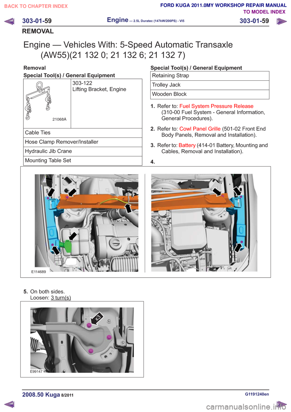
4.
E114689
5. On both sides.
Loosen: 3
turn(s)
E99147
x3
G1191240en2008.50 Kuga8/2011
303-01- 59
Engine— 2.5L Duratec (147kW/200PS) - VI5303-01-
59
REMOVAL
TO MODEL INDEX
BACK TO CHAPTER INDEX
FORD KUGA 2011.0MY WORKSHOP REPAIR MANUAL
Page 1671 of 2057
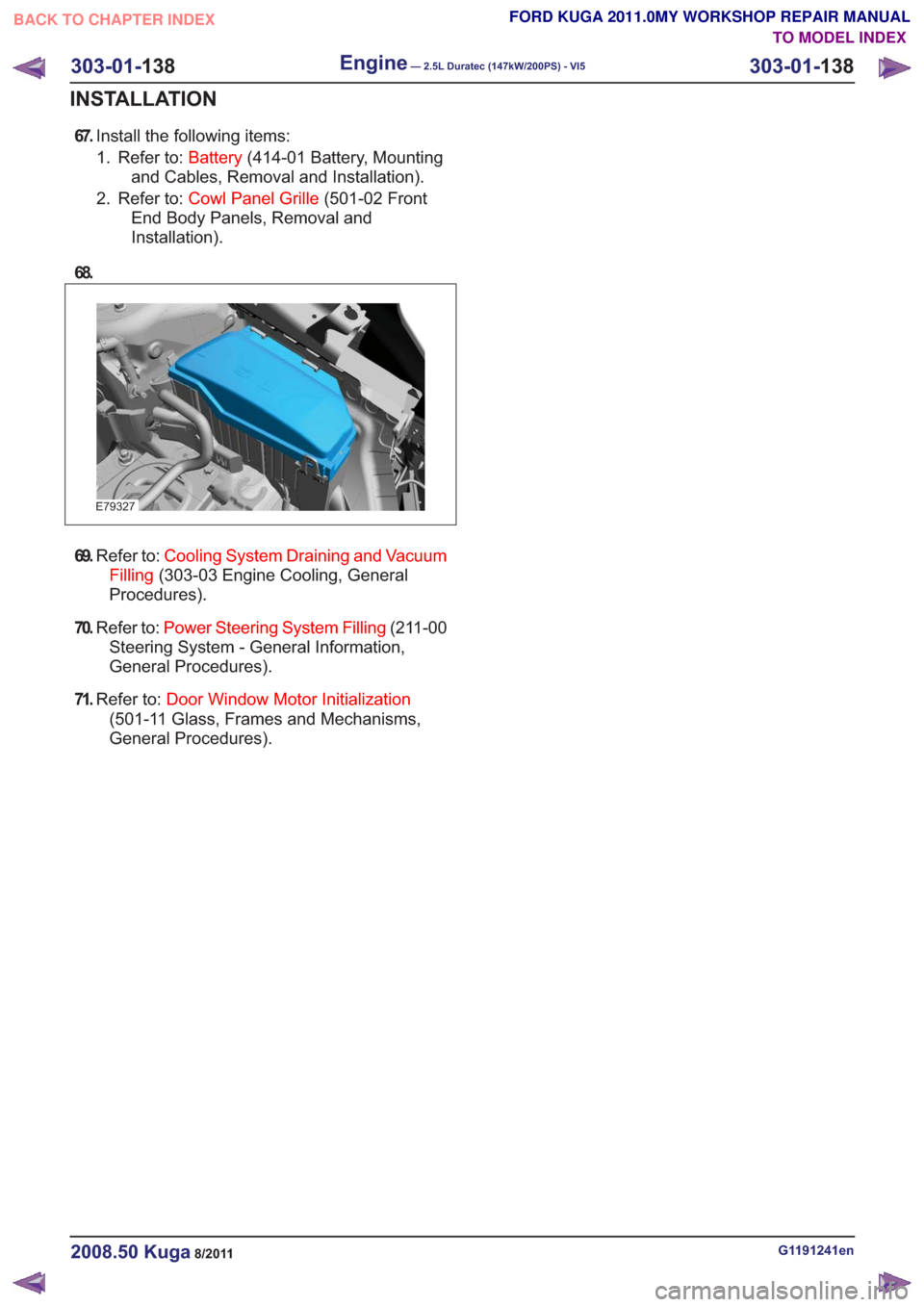
67.Install the following items:
1. Refer to: Battery(414-01 Battery, Mounting
and Cables, Removal and Installation).
2. Refer to: Cowl Panel Grille (501-02 Front
End Body Panels, Removal and
Installation).
68.
E79327
69. Refer to: Cooling System Draining and Vacuum
Filling (303-03 Engine Cooling, General
Procedures).
70. Refer to: Power Steering System Filling (211-00
Steering System - General Information,
General Procedures).
71. Refer to: Door Window Motor Initialization
(501-11 Glass, Frames and Mechanisms,
General Procedures).
G1191241en2008.50 Kuga8/2011
303-01- 138
Engine— 2.5L Duratec (147kW/200PS) - VI5303-01-
138
INSTALLATION
TO MODEL INDEX
BACK TO CHAPTER INDEX
FORD KUGA 2011.0MY WORKSHOP REPAIR MANUAL
Page 1727 of 2057
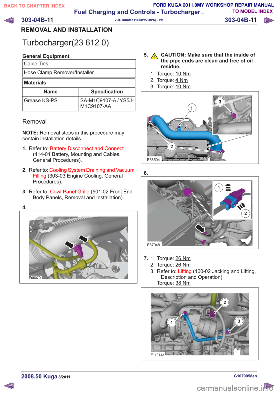
Turbocharger(23 612 0)
General EquipmentCable Ties
Hose Clamp Remover/Installer
Materials
Specification
Name
SA-M1C9107-A / YS5J-
M1C9107-AA
Grease KS-PS
Removal
NOTE:
Removal steps in this procedure may
contain installation details.
1. Refer to: Battery Disconnect and Connect
(414-01 Battery, Mounting and Cables,
General Procedures).
2. Refer to: Cooling System Draining and Vacuum
Filling (303-03 Engine Cooling, General
Procedures).
3. Refer to: Cowl Panel Grille (501-02 Front End
Body Panels, Removal and Installation).
4.
E65070
5. CAUTION: Make sure that the inside of the pipe ends are clean and free of oil
residue.
1. Torque: 10Nm
2. Torque: 4Nm
3. Torque: 10Nm
2
1
3
E68504
6.
E67948
2
1
7.Torque: 26Nm1.
2. Torque: 26
Nm
3. Refer to: Lifting(100-02 Jacking and Lifting,
Description and Operation).
Torque: 38
Nm
E112143
3
2
1
G1079058en2008.50 Kuga8/2011
303-04B- 11
Fuel Charging and Controls - Turbocharger
—
2.5L Duratec (147kW/200PS) - VI5
303-04B- 11
REMOVAL AND INSTALLATION
TO MODEL INDEX
BACK TO CHAPTER INDEX
FORD KUGA 2011.0MY WORKSHOP REPAIR MANUAL
Page 1836 of 2057
• Selector lever position and selector leverposition display
• Fluid leakage
• Transmission fluid level check
• Transmission fluid quality check
• Modification/retrofitting
• Mechanical damage to the transmission
When inspecting connectors, remember that the
plugs may only be disconnected when they are not
energized.
The transaxle electronics may be destroyed by
static charge. To prevent damage, it must be
ensured that the technician complies with the
corresponding safeguards.
NOTE: Refer to the service literature for an exact
description of these safeguards.
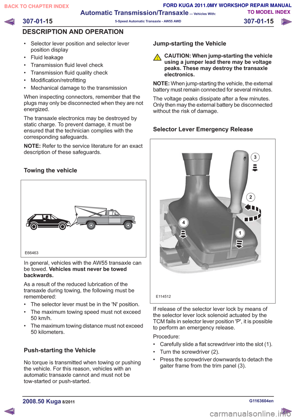
Towing the vehicle
E66463
In general, vehicles with the AW55 transaxle can
be towed. Vehicles must never be towed
backwards.
As a result of the reduced lubrication of the
transaxle during towing, the following must be
remembered:
• The selector lever must be in the 'N' position.
• The maximum towing speed must not exceed 50 km/h.
• The maximum towing distance must not exceed 50 kilometers.
Push-starting the Vehicle
No torque is transmitted when towing or pushing
the vehicle. For this reason, vehicles with an
automatic transaxle cannot and must not be
tow-started or push-started.
Jump-starting the Vehicle
CAUTION: When jump-starting the vehicle
using a jumper lead there may be voltage
peaks. These may destroy the transaxle
electronics.
NOTE: When jump-starting the vehicle, the external
battery must remain connected for several minutes.
The voltage peaks dissipate after a few minutes.
Only then may the external battery be disconnected
without the risk of damage.
Selector Lever Emergency Release
E114512
1
2
3
4
If release of the selector lever lock by means of
the selector lever lock solenoid actuated by the
TCM fails in selector lever position 'P', it is possible
to perform an emergency release.
Procedure:
• Carefully slide a flat screwdriver into the slot (1).
• Turn the screwdriver (2).
• Press the screwdriver downwards to detach the gaiter frame from the trim panel (3).
G1163604en2008.50 Kuga8/2011
307-01- 15
Automatic Transmission/Transaxle
— Vehicles With:
5-Speed Automatic Transaxle - AW55 AWD
307-01- 15
DESCRIPTION AND OPERATION
TO MODEL INDEX
BACK TO CHAPTER INDEX
FORD KUGA 2011.0MY WORKSHOP REPAIR MANUAL
Page 1843 of 2057
transmission range or gear (in select-shift mode)
is indicated to the driver in the instrument panel.
In selector lever position "S", the driver can
manually select the gears (select-shift mode). Up
(+) and down (-) shifts are made by moving the
selector lever in the appropriate direction.
Hydraulic limp home modes maintain limited
operation in the event of failure of important
electrical components.Under normal conditions, the transmission fluid is
filled for the service life of the transaxle and does
not need to be changed.
A dipstick is used to check the fluid level in the
transmission.
Functionality overview
G1163605en2008.50 Kuga8/2011
307-01-
22
Automatic Transmission/Transaxle
— Vehicles With:
5-Speed Automatic Transaxle - AW55 AWD
307-01- 22
DESCRIPTION AND OPERATION
TO MODEL INDEX
BACK TO CHAPTER INDEX
FORD KUGA 2011.0MY WORKSHOP REPAIR MANUAL
Page 1903 of 2057
Transmission
Removal
Special Tool(s) / General Equipment303-290-01
Adapter for 303-290A
2114001
303-290-03A
Adapter for 303-290A
30329003A
303-290-05A
Adapter for 303-290A
30329005A
Special Tool(s) / General Equipment303-290A
Support Bar, Engine
303290A
303-290A-14
Adapter for 303-290A
303290A14
Cable Ties
Transmission Jack
Wooden Block
1. Refer to: Health and Safety Precautions (100-00
General Information, Description and
Operation).
2. Refer to: Cowl Panel Grille (501-02 Front End
Body Panels, Removal and Installation).
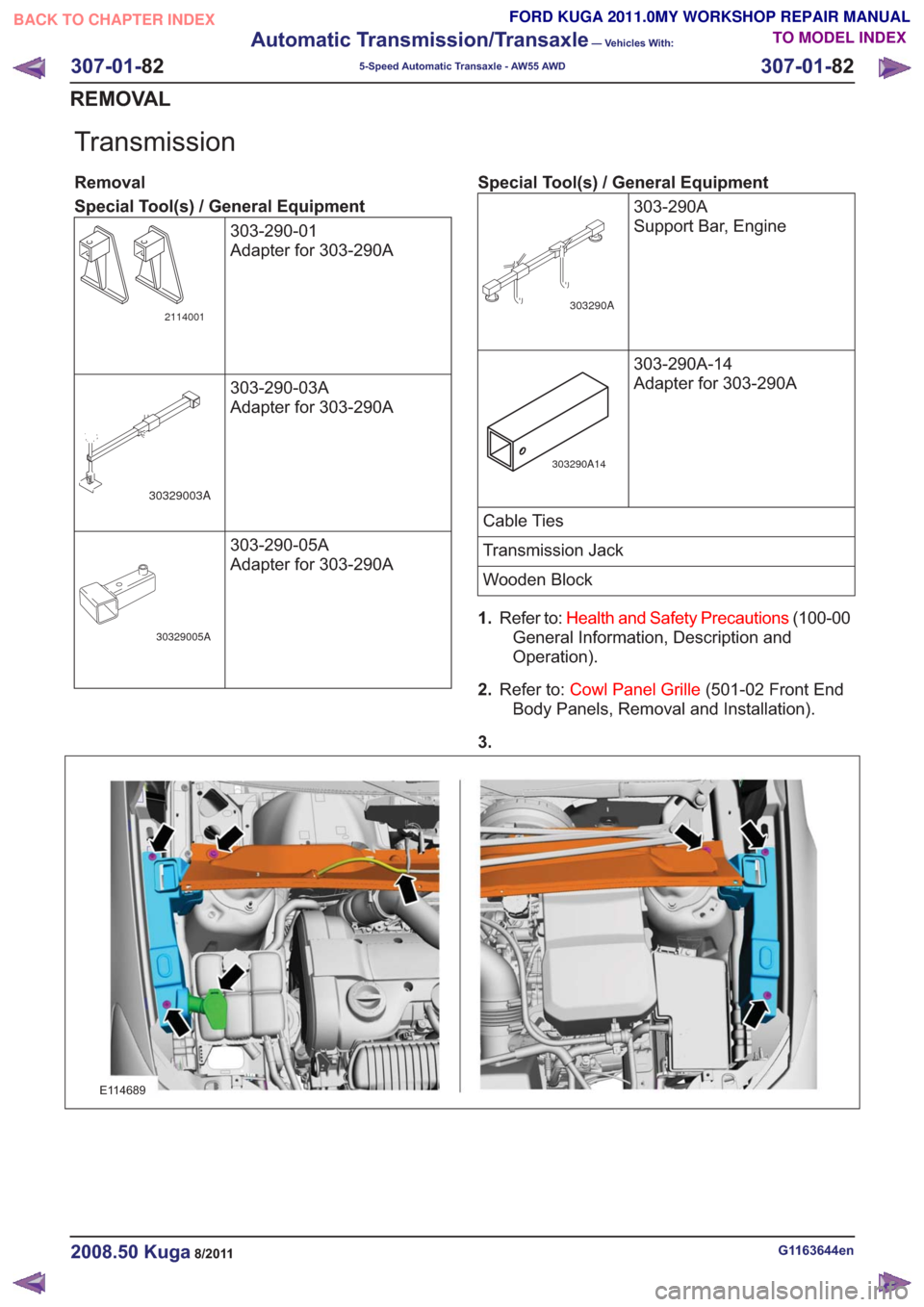
3.
E114689
G1163644en2008.50 Kuga8/2011
307-01- 82
Automatic Transmission/Transaxle
— Vehicles With:
5-Speed Automatic Transaxle - AW55 AWD
307-01- 82
REMOVAL
TO MODEL INDEX
BACK TO CHAPTER INDEX
FORD KUGA 2011.0MY WORKSHOP REPAIR MANUAL
Page 1921 of 2057
40.Torque: 10Nm
E101006
41.Refer to: Battery(414-01 Battery, Mounting and
Cables, Removal and Installation).
42. On both sides.
Torque: 35
Nm
E99147
x3
43.Refer to: Air Cleaner (303-12 Intake Air
Distribution and Filtering - 2.5L Duratec
(147kW/200PS) - VI5, Removal and
Installation).
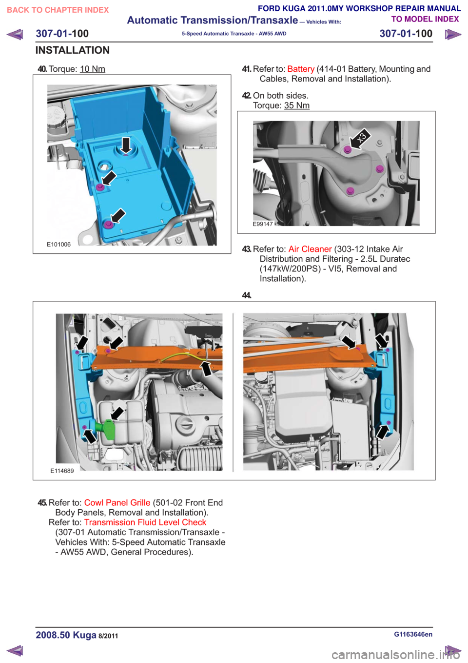
44.
E114689
45. Refer to: Cowl Panel Grille (501-02 Front End
Body Panels, Removal and Installation).
Refer to: Transmission Fluid Level Check
(307-01 Automatic Transmission/Transaxle -
Vehicles With: 5-Speed Automatic Transaxle
- AW55 AWD, General Procedures).
G1163646en2008.50 Kuga8/2011
307-01- 100
Automatic Transmission/Transaxle
— Vehicles With:
5-Speed Automatic Transaxle - AW55 AWD
307-01- 100
INSTALLATION
TO MODEL INDEX
BACK TO CHAPTER INDEX
FORD KUGA 2011.0MY WORKSHOP REPAIR MANUAL