index FORD KUGA 2011 1.G Workshop Manual
[x] Cancel search | Manufacturer: FORD, Model Year: 2011, Model line: KUGA, Model: FORD KUGA 2011 1.GPages: 2057
Page 261 of 2057
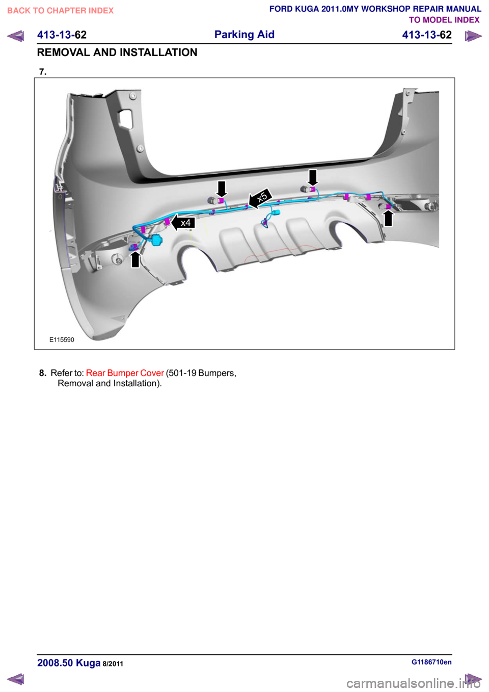
7.
8.
Refer to: Rear Bumper Cover (501-19 Bumpers,
Removal and Installation). G1186710en
2008.50 Kuga 8/2011 413-13-62
Parking Aid
413-13-62
REMOVAL AND INSTALLATIONTO MODEL INDEX
BACK TO CHAPTER INDEX
FORD KUGA 2011.0MY WORKSHOP REPAIR MANUALE115590x4x5
Page 262 of 2057
SECTION 414-00 Charging System - General
Information
VEHICLE APPLICATION:
2008.50 Kuga
PAGE
CONTENTS
DIAGNOSIS AND TESTING
414-00-2
Charging System................................................................................................................
414-00-2
Inspection and Verification..................................................................................................
414-00-2
Component Tests................................................................................................................ 414-00-1
Charging System - General Information
414-00-1
.TO MODEL INDEX
BACK TO CHAPTER INDEX
FORD KUGA 2011.0MY WORKSHOP REPAIR MANUAL
Page 263 of 2057
Charging System
Refer to Wiring Diagrams Section 414-02, for
schematic and connector information.
General Equipment
Midtronics EXP-1050 battery tester
Midtronics GR590-2
Ford diagnostic equipment
Inspection and Verification
WARNINGS: Batteries contain sulphuric acid. Avoid
contact with skin, eyes, or clothing. Also,
shield your eyes when working near
batteries to protect against possible
splashing of the acid solution. In case of
acid contact with skin or eyes, flush
immediately with water for a minimum of
15 minutes and get prompt medical
attention. If acid is swallowed, call a
physician immediately. Failure to follow
these instructions may result in personal
injury.
Batteries normally produce explosive
gases which can cause personal injury.
Therefore, do not allow flames, sparks or
lighted substances to come near the
battery. When charging or working near a
battery, always shield your face and
protect your eyes. Always provide
ventilation. Failure to follow these
instructions may result in personal injury.
1. Verify the customer concern.
2. Visually inspect for obvious signs of mechanical
or electrical damage.
Visual Inspection Chart Electrical
Mechanical
– Fuse(s)
– Wiring harness(es)
– Generator
– Electricalconnector(s)
– Battery junction box (BJB)
– Battery
– Battery cables
– Battery monitoring sensor (BMS)
– Charging system warning indicator
–
Accessory drive belt
– Generator
3. If an obvious cause for an observed or reported concern is found, correct the cause (if possible)
before proceeding to the next step.
4. Check the operation of the charging system warning indicator lamp, located in the instrument
cluster. Normal operation is as follows:
Normal Charging System Voltages Charging System
Warning Indicator Operation
Engine to
battery ground
Battery
Gener-
ator B+ Circuit
I Circuit
Ignition Switch
Position
OFF
0V
10-12V
10-12V
0V
Position 0
Illuminated
0V
10-12V
10-12V
0V
Position II
OFF
0V
13-15V
13-15V
13-15V
Position II with
the engine
running
5. If the cause is not visually evident, verify the symptom and refer to the Component Tests. Component Tests
Generator On-Vehicle Tests - No-Load Test
1. Turn off all electrical loads and the ignition
switch. G1055063en
2008.50 Kuga 8/2011 414-00-2
Charging System - General Information
414-00-2
DIAGNOSIS AND TESTINGTO MODEL INDEX
BACK TO CHAPTER INDEX
FORD KUGA 2011.0MY WORKSHOP REPAIR MANUAL
Page 264 of 2057
2. Switch the multimeter to the voltage function.
3. Connect the leads of the multimeter across the
battery terminals.
4. Read the voltage (base voltage).
5. Start the engine.
6. Run the engine at 1500 rpm with no electrical load.
7. Read the voltage. The voltage should be in the range of 14.1 volts to 15.1 volts. If the voltage
increase is less than 2.5 volts above the base
voltage, carry out the Load Test. If the voltage
increase is greater than 2.5 volts, REFER to the
Ford diagnostic equipment. Generator On-Vehicle Tests - Load Test
1. With the engine running, turn on the air
conditioning (if equipped), turn the blower motor
to high speed and the headlamps to high beam.
2. Increase the engine speed to 2000 rpm. The voltage should increase a minimum of 0.5 volts
above the base voltage. If the voltage does not
increase as specified, REFER to the Ford
approved diagnostic tool. If the voltage
increases as specified, the charging system is
charging correctly.
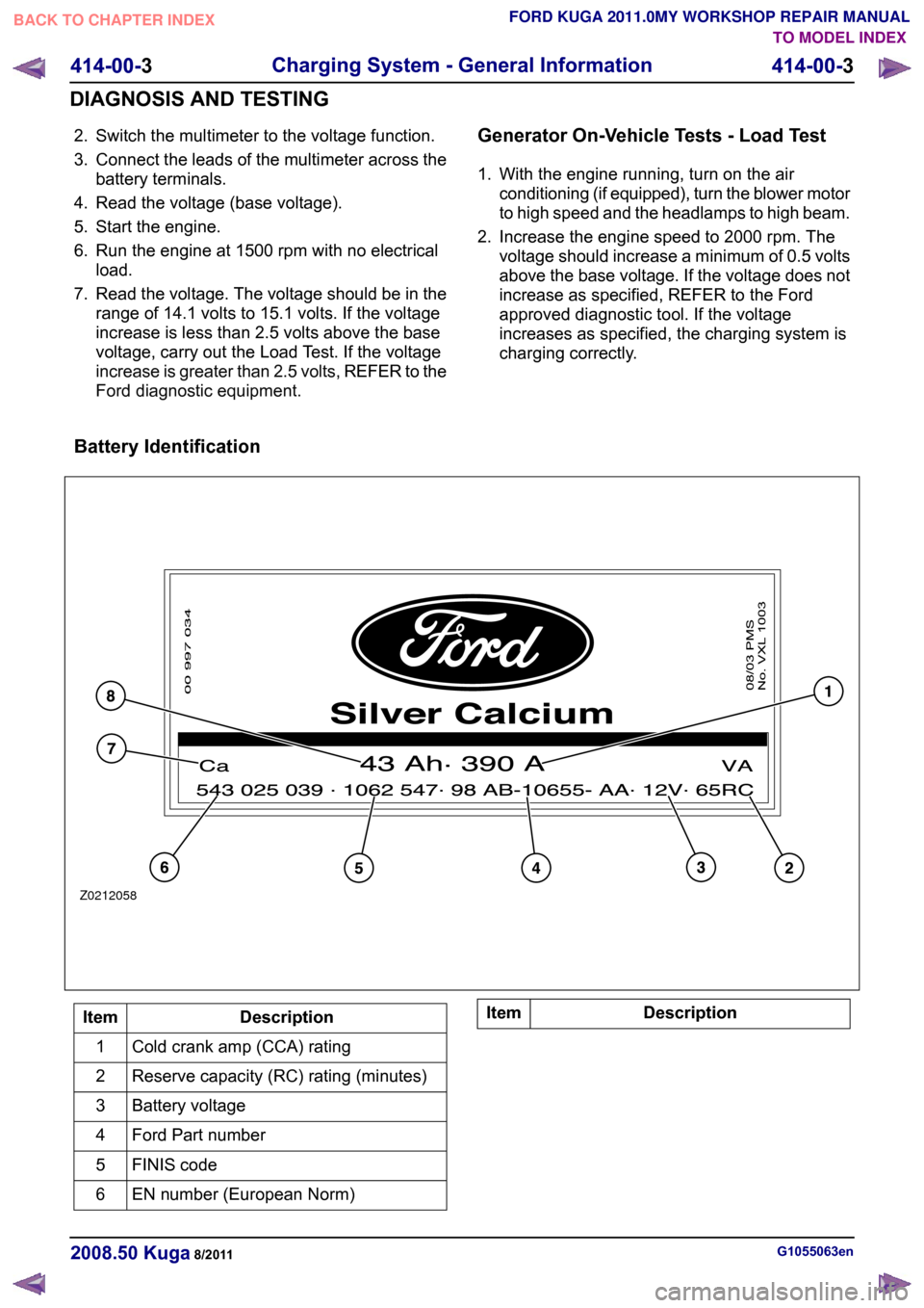
Battery Identification Description
Item
Cold crank amp (CCA) rating
1
Reserve capacity (RC) rating (minutes)
2
Battery voltage
3
Ford Part number
4
FINIS code
5
EN number (European Norm)
6 Description
Item G1055063en
2008.50 Kuga 8/2011 414-00-3
Charging System - General Information
414-00-3
DIAGNOSIS AND TESTINGTO MODEL INDEX
BACK TO CHAPTER INDEX
FORD KUGA 2011.0MY WORKSHOP REPAIR MANUALZ0212058
Page 266 of 2057
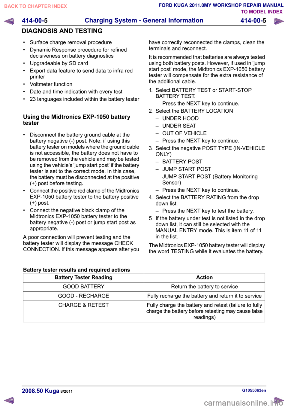
• Surface charge removal procedure
• Dynamic Response procedure for refined
decisiveness on battery diagnostics
• Upgradeable by SD card
• Export data feature to send data to infra red printer
• Voltmeter function
• Date and time indication with every test
• 23 languages included within the battery tester
Using the Midtronics EXP-1050 battery
tester
• Disconnect the battery ground cable at the battery negative (-) post. Note: if using this
battery tester on models where the ground cable
is not accessible, the battery does not have to
be removed from the vehicle and may be tested
using the vehicle's 'jump start post' if the battery
tester is set to the correct mode. In this case,
the battery must be disconnected at the positive
(+) post before testing.
• Connect the positive red clamp of the Midtronics
EXP-1050 battery tester to the battery positive
(+) post.
• Connect the negative black clamp of the Midtronics EXP-1050 battery tester to the
battery negative (-) post or jump start post as
appropriate.
A poor connection will prevent testing and the
battery tester will display the message CHECK
CONNECTION. If this message appears after you have correctly reconnected the clamps, clean the
terminals and reconnect.
It is recommended that batteries are always tested
using both battery posts. However, if used in 'jump
start post' mode, the Midtronics EXP-1050 battery
tester will compensate for the extra resistance of
the additional cable.
1.
Select BATTERY TEST or START-STOP
BATTERY TEST.
– Press the NEXT key to continue.
2. Select the BATTERY LOCATION
– UNDER HOOD
– UNDER SEAT
– OUT OF VEHICLE
– Press the NEXT key to continue.
3. Select the negative POST TYPE (IN-VEHICLE
ONLY)
– BATTERY POST
– JUMP START POST
– JUMP START POST (Battery Monitoring
Sensor)
– Press the NEXT key to continue.
4. Select the BATTERY RATING from the drop
down list.
– Press the NEXT key to test the battery.
5. If the battery under test is not listed in the drop
down list, it can still be selected with the
MANUAL ENTRY mode. This is item 11 of 11
in the list.
The Midtronics EXP-1050 battery tester will display
the word TESTING while it evaluates the battery.
Battery tester results and required actions Action
Battery Tester Reading
Return the battery to service
GOOD BATTERY
Fully recharge the battery and return it to service
GOOD - RECHARGE
Fully charge the battery and retest (failure to fully
charge the battery before retesting may cause false readings)
CHARGE & RETEST G1055063en
2008.50 Kuga 8/2011 414-00-5
Charging System - General Information
414-00-5
DIAGNOSIS AND TESTINGTO MODEL INDEX
BACK TO CHAPTER INDEX
FORD KUGA 2011.0MY WORKSHOP REPAIR MANUAL
Page 267 of 2057
Action
Battery Tester Reading WARNING: Do not recharge the battery.
Make sure that the surface charge was removed. A "REPLACE BATTERY" result could also mean
a poor connection between the battery cables and the battery. Check the connections are OK and
retest. If the result remains the same, INSTALL a NEW battery
REFER to: Battery(414-01 Battery, Mounting and
Cables, Removal and Installation).
REPLACE BATTERY or BAD CELL BATTERY
In addition it is advisable to check the vehicle electrical system. Check that the generator is functioning
correctly and the vehicle does not have an excessive key-off load (in general this should be under
20mA after 40 minutes of key off).
Midtronics EXP-1050 Battery Tester Test
Code
At the end of the test, use the arrow keys to scroll
down the screens to see additional information.
One of these is the TEST CODE.
The TEST CODE has 11 digits, for example:
0021U-B88WKX.
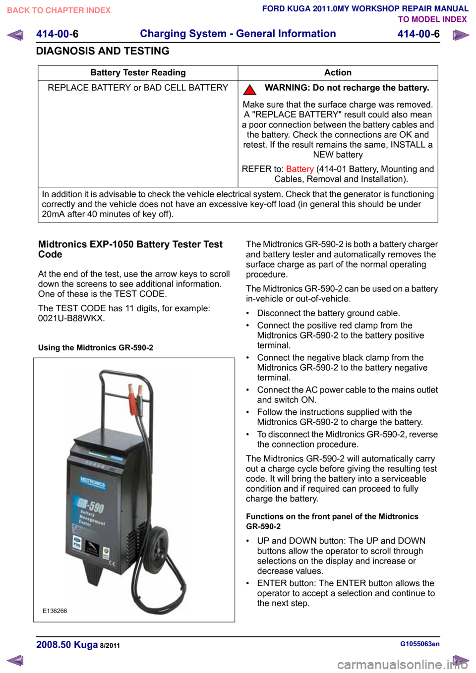
Using the Midtronics GR-590-2 The Midtronics GR-590-2 is both a battery charger
and battery tester and automatically removes the
surface charge as part of the normal operating
procedure.
The Midtronics GR-590-2 can be used on a battery
in-vehicle or out-of-vehicle.
• Disconnect the battery ground cable.
• Connect the positive red clamp from the
Midtronics GR-590-2 to the battery positive
terminal.
• Connect the negative black clamp from the Midtronics GR-590-2 to the battery negative
terminal.
• Connect the AC power cable to the mains outlet
and switch ON.
• Follow the instructions supplied with the Midtronics GR-590-2 to charge the battery.
• To disconnect the Midtronics GR-590-2, reverse
the connection procedure.
The Midtronics GR-590-2 will automatically carry
out a charge cycle before giving the resulting test
code. It will bring the battery into a serviceable
condition and if required can proceed to fully
charge the battery.
Functions on the front panel of the Midtronics
GR-590-2
• UP and DOWN button: The UP and DOWN buttons allow the operator to scroll through
selections on the display and increase or
decrease values.
• ENTER button: The ENTER button allows the operator to accept a selection and continue to
the next step. G1055063en
2008.50 Kuga 8/2011 414-00-6
Charging System - General Information
414-00-6
DIAGNOSIS AND TESTINGTO MODEL INDEX
BACK TO CHAPTER INDEX
FORD KUGA 2011.0MY WORKSHOP REPAIR MANUALE136266
Page 268 of 2057
• INFO button: The INFO button allows the
operator to enter the Options menu to access
feature such as Languages, BMC Code, Last
Test Data and Print.
• STOP button: The STOP button allows the operator to abort a charging cycle or go back to
previous steps in the menus.
Midtronics GR-590-2 Test Code
At the end of the test, use the arrow keys to scroll
down the screens to see additional information.
One of these is the TEST CODE.
The TEST CODE has 13 digits, for example:
Y74NH-58R36-ESV. G1055063en
2008.50 Kuga 8/2011 414-00-7
Charging System - General Information
414-00-7
DIAGNOSIS AND TESTINGTO MODEL INDEX
BACK TO CHAPTER INDEX
FORD KUGA 2011.0MY WORKSHOP REPAIR MANUAL
Page 269 of 2057
SECTION 414-01 Battery, Mounting and Cables
VEHICLE APPLICATION:
2008.50 Kuga
PAGE
CONTENTS
GENERAL PROCEDURES
414-01-2
Battery Disconnect and Connect........................................................................................
414-01-2
Disconnect ..........................................................................................................................
414-01-3
Connect ..............................................................................................................................
REMOVAL AND INSTALLATION 414-01-4
Battery ................................................................................................................................ 414-01-1
Battery, Mounting and Cables
414-01-1
.TO MODEL INDEX
BACK TO CHAPTER INDEX
FORD KUGA 2011.0MY WORKSHOP REPAIR MANUAL
Page 270 of 2057
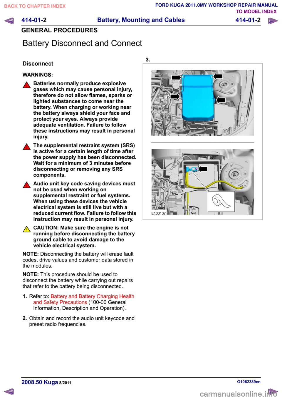
Battery Disconnect and Connect
Disconnect
WARNINGS:
Batteries normally produce explosive
gases which may cause personal injury,
therefore do not allow flames, sparks or
lighted substances to come near the
battery. When charging or working near
the battery always shield your face and
protect your eyes. Always provide
adequate ventilation. Failure to follow
these instructions may result in personal
injury.
The supplemental restraint system (SRS)
is active for a certain length of time after
the power supply has been disconnected.
Wait for a minimum of 3 minutes before
disconnecting or removing any SRS
components.
Audio unit key code saving devices must
not be used when working on
supplemental restraint or fuel systems.
When using these devices the vehicle
electrical system is still live but with a
reduced current flow. Failure to follow this
instruction may result in personal injury.
CAUTION: Make sure the engine is not
running before disconnecting the battery
ground cable to avoid damage to the
vehicle electrical system.
NOTE: Disconnecting the battery will erase fault
codes, drive values and customer data stored in
the modules.
NOTE: This procedure should be used to
disconnect the battery while carrying out repairs
that refer to the battery being disconnected.
1. Refer to: Battery and Battery Charging Health
and Safety Precautions (100-00 General
Information, Description and Operation).
2. Obtain and record the audio unit keycode and
preset radio frequencies. 3.
G1062389en
2008.50 Kuga 8/2011 414-01-2
Battery, Mounting and Cables
414-01-2
GENERAL PROCEDURESTO MODEL INDEX
BACK TO CHAPTER INDEX
FORD KUGA 2011.0MY WORKSHOP REPAIR MANUALE103137
Page 271 of 2057
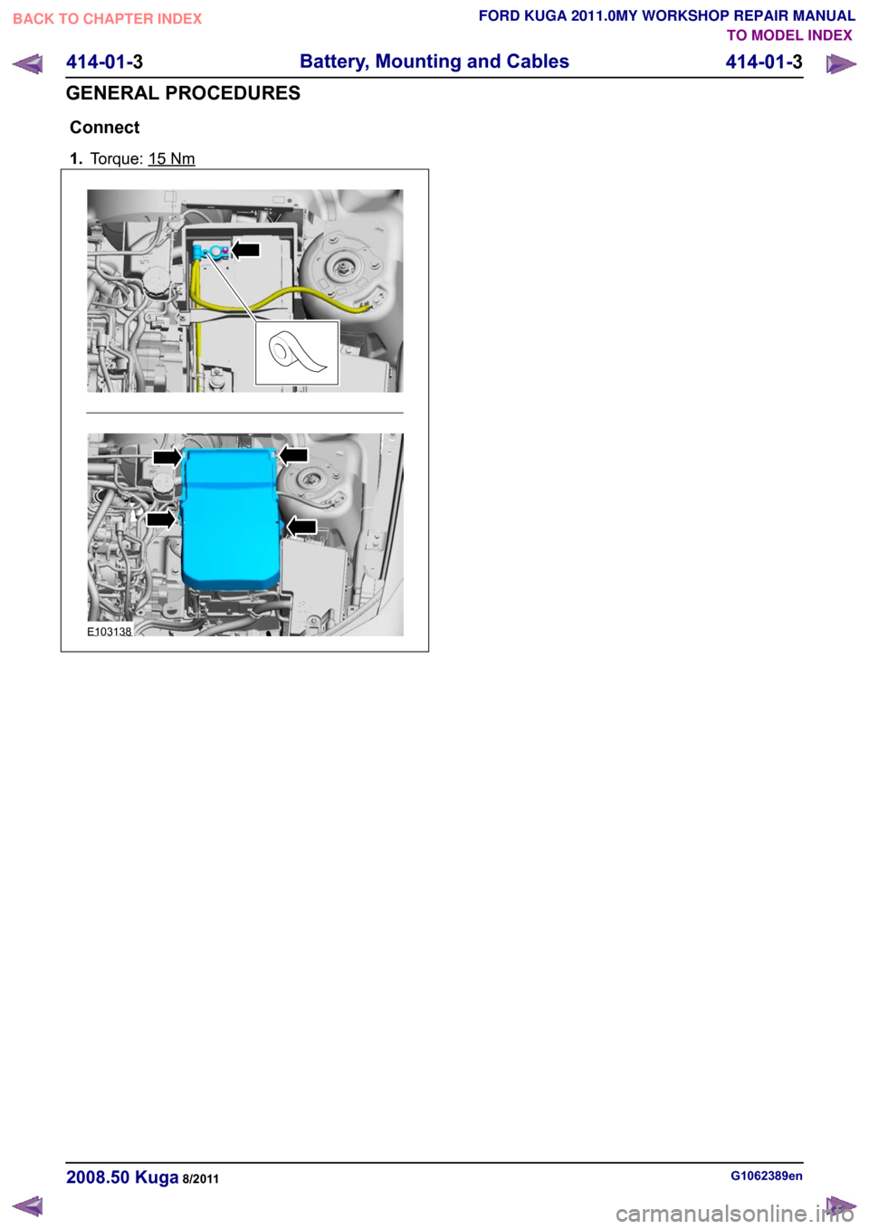
Connect
1.
Torque: 15 Nm
G1062389en
2008.50 Kuga 8/2011 414-01-3
Battery, Mounting and Cables
414-01-3
GENERAL PROCEDURESTO MODEL INDEX
BACK TO CHAPTER INDEX
FORD KUGA 2011.0MY WORKSHOP REPAIR MANUALE103138