index FORD KUGA 2011 1.G Workshop Manual
[x] Cancel search | Manufacturer: FORD, Model Year: 2011, Model line: KUGA, Model: FORD KUGA 2011 1.GPages: 2057
Page 272 of 2057
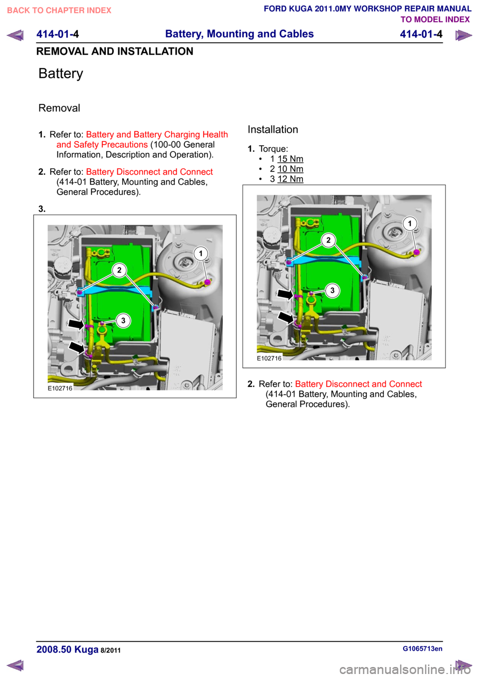
Battery
Removal
1.
Refer to: Battery and Battery Charging Health
and Safety Precautions (100-00 General
Information, Description and Operation).
2. Refer to: Battery Disconnect and Connect
(414-01 Battery, Mounting and Cables,
General Procedures).
3. Installation
1.
Torque:
• 1 15 Nm
• 2 10 Nm
• 3 12 Nm
2.
Refer to: Battery Disconnect and Connect
(414-01 Battery, Mounting and Cables,
General Procedures). G1065713en
2008.50 Kuga 8/2011 414-01-4
Battery, Mounting and Cables
414-01-4
REMOVAL AND INSTALLATIONTO MODEL INDEX
BACK TO CHAPTER INDEX
FORD KUGA 2011.0MY WORKSHOP REPAIR MANUALE102716123 E102716123
Page 273 of 2057

SECTION 414-02 Generator and Regulator
VEHICLE APPLICATION:
2008.50 Kuga
PAGE
CONTENTS
DESCRIPTION AND OPERATION
414-02-2
Generator ............................................................................................................................
414-02-2
Smart Charge system.........................................................................................................
REMOVAL AND INSTALLATION 414-02-3
(31 414 0)
Generator — 2.5L Duratec (147kW/200PS) - VI5.......................................... 414-02-1
Generator and Regulator
414-02-1
.TO MODEL INDEX
BACK TO CHAPTER INDEX
FORD KUGA 2011.0MY WORKSHOP REPAIR MANUAL
Page 274 of 2057

Generator
General information
The powertrain control module (PCM) controls the
alternator charging voltage. The connection
between the PCM and the generator is made via
the control module subnetwork (LIN) bus.
If the load on the alternator is high, the PCM can
increase the idle speed.
The alternator is temporarily deactivated during
engine starting so that the engine drag moment is
minimized and it is reactivated again after the
starting procedure.
The PCM controls the charge control lamp in the
instrument cluster via the controller area network
(CAN) bus.
Smart Charge system
In addition to the familiar functions, the Smart
Charge system also performs the following
functions:
•
Automatic deactivation of non-critical high power
electrical consumers when the battery voltage
is low in order to reduce the level of current
drawn.
• Automatic activation of non-critical high power electrical consumers when the battery voltage
is excessively high in order to protect
components which are sensitive to increased
voltages.
The battery charging current is optimized through
continuous calculation of the battery temperature
and monitoring of the alternator output voltage.
By receiving the forwarded alternator load signal,
the PCM is given early warning whenever an
electric consumer is switched on or off. This means
that the PCM receives information about imminent
changes in the torque drawn by the alternator. By
evaluating this information the PCM can provide a
higher level of idling stability.
The two remaining functions of the Smart Charge
System are controlled by the GEM.
Electrical consumers are switched off due to low
voltage when the GEM determines (on the basis
of the message received from the PCM on the CAN
bus via the instrument cluster) that the battery
voltage has dropped below the threshold.
When the threshold for low battery voltage is
reached the GEM automatically deactivates the following consumers - in this order and with a gap
of 5 seconds between each:
• Electric booster heater (vehicles with diesel
engines)
• Heated exterior mirrors
• Heated rear window
• Heated windscreen
If the battery voltage rises back above the lower
threshold then the GEM re-enables all of the
electrical consumers which were previously
disabled. They then have switched off status and
must be switched back on by the driver.
Electrical consumers are switched on due to
excessively high voltage if the GEM determines
that the battery voltage is above the threshold for
overvoltage and the charge control lamp has been
switched on.
When the threshold is reached the GEM
automatically activates the following consumers -
in this order and with a gap of 5 seconds between
each:
• Heated rear window
• Heated exterior mirrors
• Electric booster heater (vehicles with diesel engines)
• Blower motor
If the battery voltage drops back below the
threshold then the GEM automatically deactivates
any consumers that were switched on. However,
if they were switched on by the driver before the
automatic activation, they will then be switched on
again in turn with a 5-second time interval. G964174en
2008.50 Kuga 8/2011 414-02-2
Generator and Regulator
414-02-2
DESCRIPTION AND OPERATIONTO MODEL INDEX
BACK TO CHAPTER INDEX
FORD KUGA 2011.0MY WORKSHOP REPAIR MANUAL
Page 276 of 2057
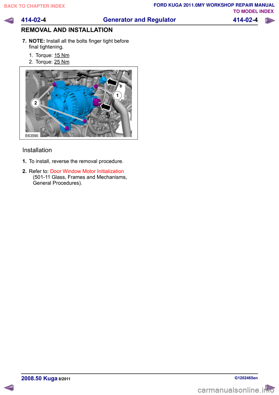
7. NOTE:
Install all the bolts finger tight before
final tightening.
1. Torque: 15 Nm
2. Torque: 25 Nm
Installation
1.
To install, reverse the removal procedure.
2. Refer to: Door Window Motor Initialization
(501-11 Glass, Frames and Mechanisms,
General Procedures). G1202465en
2008.50 Kuga 8/2011 414-02-4
Generator and Regulator
414-02-4
REMOVAL AND INSTALLATIONTO MODEL INDEX
BACK TO CHAPTER INDEX
FORD KUGA 2011.0MY WORKSHOP REPAIR MANUALE6359021
Page 277 of 2057
SECTION 414-05 Voltage Converter/Inverter
VEHICLE APPLICATION:
2008.50 Kuga
PAGE
CONTENTS
DESCRIPTION AND OPERATION
414-05-2
Direct Current/Alternating Current (DC/AC) Inverter (Component Location)......................
414-05-3
Direct Current/Alternating Current (DC/AC) Inverter (Overview)........................................
414-05-3
Function indicator...............................................................................................................
414-05-4
Direct Current/Alternating Current (DC/AC) Inverter (System Operation and Component
Description) .......................................................................................................................
414-05-4
System Diagram.................................................................................................................
414-05-4
System Operation...............................................................................................................
414-05-4
DC/AC converter.............................................................................................................
414-05-5
Component Description......................................................................................................
414-05-5
DC/AC converter.............................................................................................................
414-05-5
AC mains outlet...............................................................................................................
REMOVAL AND INSTALLATION 414-05-7
Direct Current/Alternating Current (DC/AC) Inverter.......................................................... 414-05-1
Voltage Converter/Inverter
414-05-1
.TO MODEL INDEX
BACK TO CHAPTER INDEX
FORD KUGA 2011.0MY WORKSHOP REPAIR MANUAL
Page 278 of 2057
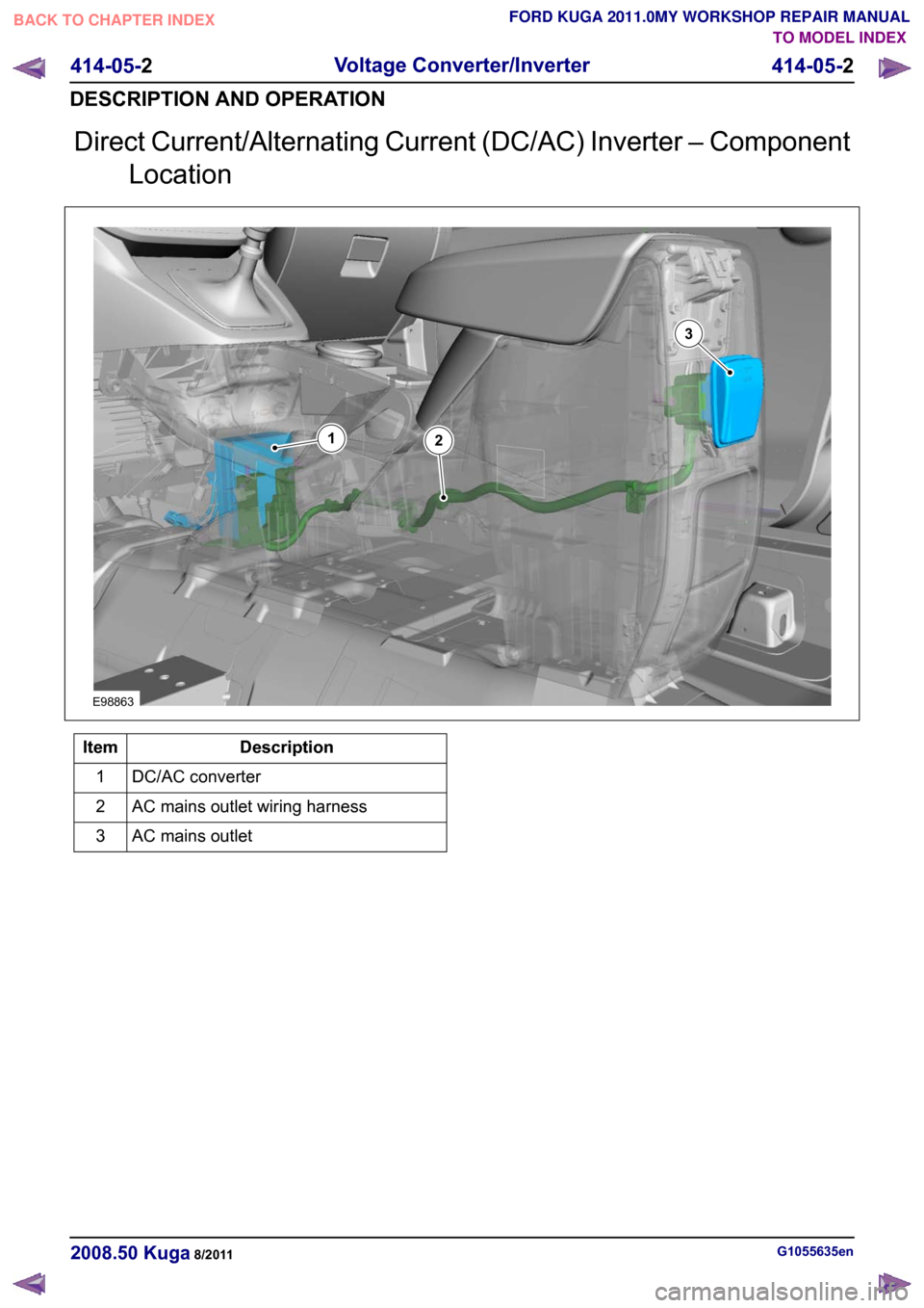
Direct Current/Alternating Current (DC/AC) Inverter – Component
Location Description
Item
DC/AC converter
1
AC mains outlet wiring harness
2
AC mains outlet
3 G1055635en
2008.50 Kuga 8/2011 414-05-2
Voltage Converter/Inverter
414-05-2
DESCRIPTION AND OPERATIONTO MODEL INDEX
BACK TO CHAPTER INDEX
FORD KUGA 2011.0MY WORKSHOP REPAIR MANUALE98863132
Page 279 of 2057

Direct Current/Alternating Current (DC/AC) Inverter – Overview
Function indicator
WARNING: For workshop repairs, it is only
permissible to replace the converter as a
complete unit together with the wiring
harness and the socket. The component
must not be opened, as charged capacitors
inside can still carry dangerously high
residual voltages.
The LED in the socket lights up orange when the
converter is supplying a voltage.
In the event of a fault the system switches off and
indicates the cause of the fault by flashing a trouble
code via the LED in the socket:
• 1x flash – High temperature
• 2x flashes – Overload
• 3x flashes – Internal overvoltage
• 4x flashes – Internal undervoltage
• Continuous flashing – Short circuit to power
If the converter switches off due to high
temperature then it switches back on again
automatically once the temperature has cooled
down sufficiently.
With all of the other faults which are displayed, the
converter can be reset by switching the ignition off
and back on again or by unplugging and reinserting
the consumer in the socket.
If these measures are unsuccessful then there are
no further options for directly influencing the
function yourself. G1055637en
2008.50 Kuga 8/2011 414-05-3
Voltage Converter/Inverter
414-05-3
DESCRIPTION AND OPERATIONTO MODEL INDEX
BACK TO CHAPTER INDEX
FORD KUGA 2011.0MY WORKSHOP REPAIR MANUAL
Page 280 of 2057
Direct Current/Alternating Current (DC/AC) Inverter – System
Operation and Component Description
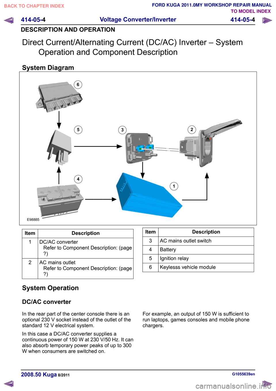
System Diagram Description
Item
DC/AC converterRefer to Component Description: (page
?)
1
AC mains outletRefer to Component Description: (page
?)
2 Description
Item
AC mains outlet switch
3
Battery
4
Ignition relay
5
Keylesss vehicle module
6
System Operation
DC/AC converter
In the rear part of the center console there is an
optional 230 V socket instead of the outlet of the
standard 12 V electrical system.
In this case a DC/AC converter supplies a
continuous power of 150 W at 230 V/50 Hz. It can
also absorb temporary power peaks of up to 300
W when consumers are switched on. For example, an output of 150 W is sufficient to
run laptops, games consoles and mobile phone
chargers.
G1055639en
2008.50 Kuga 8/2011 414-05-4
Voltage Converter/Inverter
414-05-4
DESCRIPTION AND OPERATIONTO MODEL INDEX
BACK TO CHAPTER INDEX
FORD KUGA 2011.0MY WORKSHOP REPAIR MANUAL12456E988853
Page 281 of 2057
Component Description
DC/AC converter
The converter operates with a series connection
of two power converter circuits. The primary power
converter here is a push-pull converter. It converts
the 12 V supply from the electrical system of the
vehicle to an intermediate direct current link of
approx. 320 V.
From this intermediate direct current link, the
downstream full H-bridge circuit generates a
pulse-width modulated output voltage with 230
V/50 Hz.
A controller modulates the pulse width of the
square-wave output voltage and maintains an
effective output voltage of 230 V under varying
load conditions and under different input voltages.
Here, the rising and falling edge of the positive and
negative square wave pulse are controlled
symmetrically to the ideal shape of a sine wave,
which - among other things - also makes a positive
contribution to electromagnetic compatibility.
DC/AC converters which supply a modified square
wave output voltage are referred to as 'Modified
Sine Wave Inverters".
With this type of system there is no need for a
residual current operated device for protection in
the event of accidental contact, as all of the 230 V
lines are double-insulated. Potential-free separation
of the entire 230 V voltage part from the vehicle is
provided (electrical isolation).
The output voltage of 230 V/50 Hz is not generated
until the switching voltage is present at terminal 1
of the converter via the AC mains outlet switch.
The converter operates with the ignition switched
on and a vehicle electrical supply of between 11
V and 16 V. Internal voltage monitoring in the converter deactivates the system if the input
voltage is outside this range.
AC mains outlet
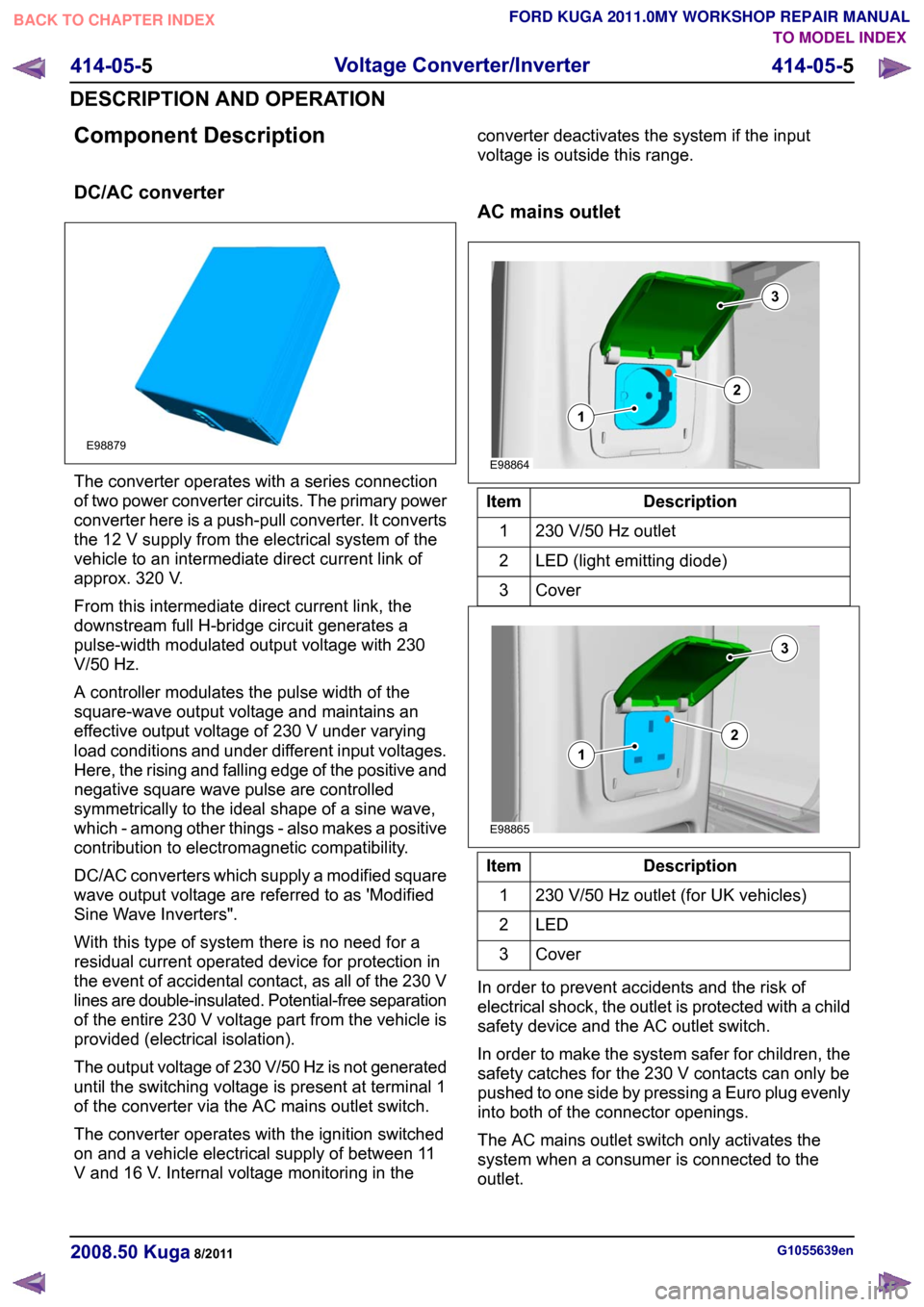
Description
Item
230 V/50 Hz outlet
1
LED (light emitting diode)
2
Cover3 Description
Item
230 V/50 Hz outlet (for UK vehicles)
1
LED2
Cover3
In order to prevent accidents and the risk of
electrical shock, the outlet is protected with a child
safety device and the AC outlet switch.
In order to make the system safer for children, the
safety catches for the 230 V contacts can only be
pushed to one side by pressing a Euro plug evenly
into both of the connector openings.
The AC mains outlet switch only activates the
system when a consumer is connected to the
outlet. G1055639en
2008.50 Kuga 8/2011 414-05-5
Voltage Converter/Inverter
414-05-5
DESCRIPTION AND OPERATIONTO MODEL INDEX
BACK TO CHAPTER INDEX
FORD KUGA 2011.0MY WORKSHOP REPAIR MANUALE98879 E98864312 E98865312
Page 282 of 2057

The contacts of the outlet exert a more powerful
grip on the plug so that it does not shake loose on
poor road surfaces. An orange LED lights up to
show that the unit has been activated.
G1055639en
2008.50 Kuga 8/2011 414-05-6
Voltage Converter/Inverter
414-05-6
DESCRIPTION AND OPERATIONTO MODEL INDEX
BACK TO CHAPTER INDEX
FORD KUGA 2011.0MY WORKSHOP REPAIR MANUAL