check engine FORD KUGA 2011 1.G Owner's Manual
[x] Cancel search | Manufacturer: FORD, Model Year: 2011, Model line: KUGA, Model: FORD KUGA 2011 1.GPages: 2057
Page 1233 of 2057
Wheels and Tires
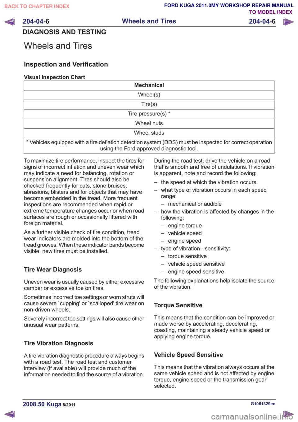
Inspection and Verification
Visual Inspection Chart
MechanicalWheel(s)Tire(s)
Tire pressure(s) * Wheel nuts
Wheel studs
* Vehicles equipped with a tire deflation detection system (DDS) must be inspected for correct operation using the Ford approved diagnostic tool.
To maximize tire performance, inspect the tires for
signs of incorrect inflation and uneven wear which
may indicate a need for balancing, rotation or
suspension alignment. Tires should also be
checked frequently for cuts, stone bruises,
abrasions, blisters and for objects that may have
become embedded in the tread. More frequent
inspections are recommended when rapid or
extreme temperature changes occur or when road
surfaces are rough or occasionally littered with
foreign material.
As a further visible check of tire condition, tread
wear indicators are molded into the bottom of the
tread grooves. When these indicator bands become
visible, new tires must be installed.
Tire Wear Diagnosis
Uneven wear is usually caused by either excessive
camber or excessive toe on tires.
Sometimes incorrect toe settings or worn struts will
cause severe `cupping' or `scalloped' tire wear on
non-driven wheels.
Severely incorrect toe settings will also cause other
unusual wear patterns.
Tire Vibration Diagnosis
A tire vibration diagnostic procedure always begins
with a road test. The road test and customer
interview (if available) will provide much of the
information needed to find the source of a vibration. During the road test, drive the vehicle on a road
that is smooth and free of undulations. If vibration
is apparent, note and record the following:
– the speed at which the vibration occurs.
– what type of vibration occurs in each speed
range.
– mechanical or audible
– how the vibration is affected by changes in the following:
– engine torque
– vehicle speed
– engine speed
– type of vibration - sensitivity: – torque sensitive
– vehicle speed sensitive
– engine speed sensitive
The following explanations help isolate the source
of the vibration.
Torque Sensitive
This means that the condition can be improved or
made worse by accelerating, decelerating,
coasting, maintaining a steady vehicle speed or
applying engine torque.
Vehicle Speed Sensitive
This means that the vibration always occurs at the
same vehicle speed and is not affected by engine
torque, engine speed or the transmission gear
selected.
G1061329en2008.50 Kuga8/2011
204-04- 6
Wheels and Tires
204-04- 6
DIAGNOSIS AND TESTING
TO MODEL INDEX
BACK TO CHAPTER INDEX
FORD KUGA 2011.0MY WORKSHOP REPAIR MANUAL
Page 1269 of 2057
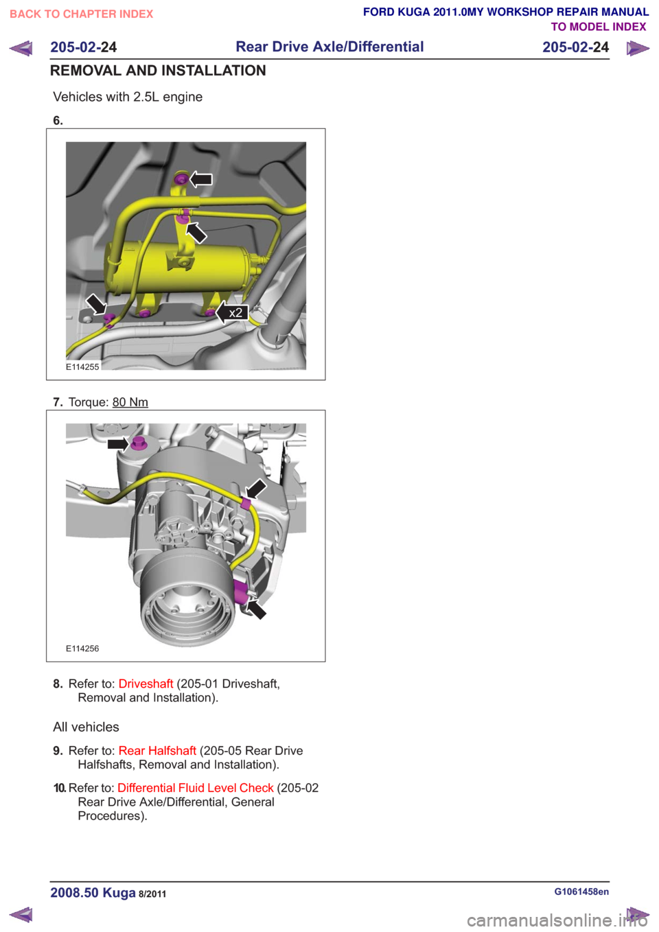
Vehicles with 2.5L engine
6.
x2x2
E114255
7.Torque: 80Nm
E114256
8.Refer to: Driveshaft (205-01 Driveshaft,
Removal and Installation).
All vehicles
9. Refer to: Rear Halfshaft (205-05 Rear Drive
Halfshafts, Removal and Installation).
10. Refer to: Differential Fluid Level Check (205-02
Rear Drive Axle/Differential, General
Procedures).
G1061458en2008.50 Kuga8/2011
205-02- 24
Rear Drive Axle/Differential
205-02- 24
REMOVAL AND INSTALLATION
TO MODEL INDEX
BACK TO CHAPTER INDEX
FORD KUGA 2011.0MY WORKSHOP REPAIR MANUAL
Page 1299 of 2057
Action
Possible Sources
Symptom
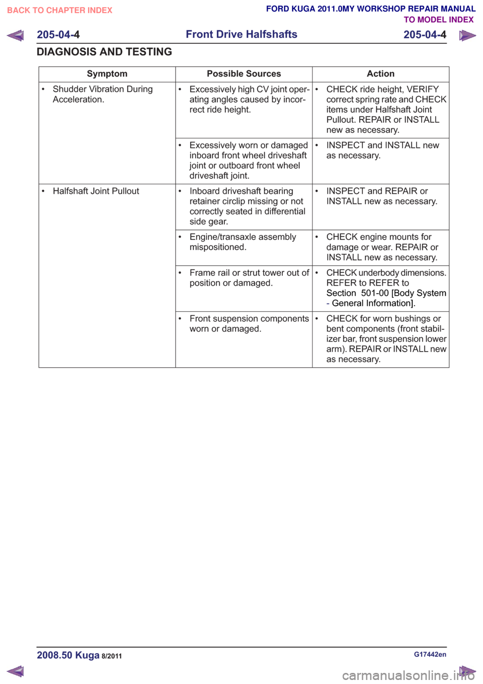
• CHECK ride height, VERIFYcorrect spring rate and CHECK
items under Halfshaft Joint
Pullout. REPAIR or INSTALL
new as necessary.
• Excessively high CV joint oper-
ating angles caused by incor-
rect ride height.
• Shudder Vibration During
Acceleration.
• INSPECT and INSTALL newas necessary.
• Excessively worn or damaged
inboard front wheel driveshaft
joint or outboard front wheel
driveshaft joint.
• INSPECT and REPAIR orINSTALL new as necessary.
• Inboard driveshaft bearing
retainer circlip missing or not
correctly seated in differential
side gear.
• Halfshaft Joint Pullout
• CHECK engine mounts fordamage or wear. REPAIR or
INSTALL new as necessary.
• Engine/transaxle assembly
mispositioned.
• CHECK underbody dimensions.REFER to REFER to
Section 501-00 [Body System
-General Information] .
• Frame rail or strut tower out of
position or damaged.
• CHECK for worn bushings orbent components (front stabil-
izer bar, front suspension lower
arm). REPAIR or INSTALL new
as necessary.
• Front suspension components
worn or damaged.
G17442en2008.50 Kuga8/2011
205-04- 4
Front Drive Halfshafts
205-04- 4
DIAGNOSIS AND TESTING
TO MODEL INDEX
BACK TO CHAPTER INDEX
FORD KUGA 2011.0MY WORKSHOP REPAIR MANUAL
Page 1344 of 2057
Action
Possible Sources
Symptom
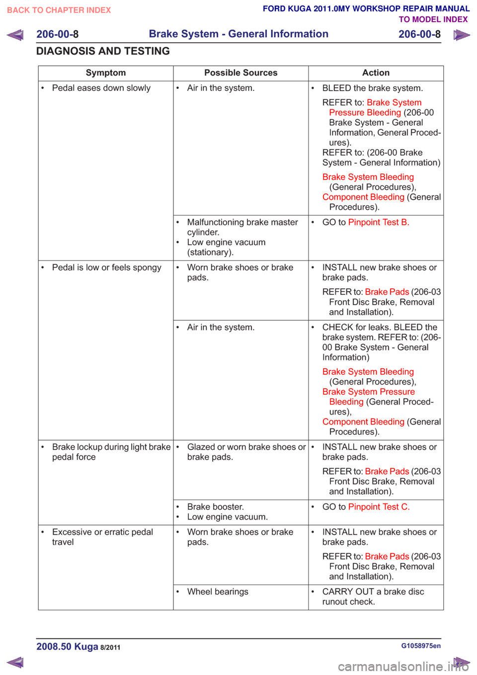
• BLEED the brake system.REFER to: Brake System
Pressure Bleeding (206-00
Brake System - General
Information, General Proced-
ures).
REFER to: (206-00 Brake
System - General Information)
Brake System Bleeding (General Procedures),
Component Bleeding (General
Procedures).
• Air in the system.
• Pedal eases down slowly
• GO toPinpoint Test B.
• Malfunctioning brake master
cylinder.
• Low engine vacuum (stationary).
• INSTALL new brake shoes orbrake pads.
REFER to: Brake Pads (206-03
Front Disc Brake, Removal
and Installation).
• Worn brake shoes or brake
pads.
• Pedal is low or feels spongy
• CHECK for leaks. BLEED thebrake system. REFER to: (206-
00 Brake System - General
Information)
Brake System Bleeding (General Procedures),
Brake System Pressure Bleeding (General Proced-
ures),
Component Bleeding (General
Procedures).
• Air in the system.
• INSTALL new brake shoes orbrake pads.
REFER to: Brake Pads (206-03
Front Disc Brake, Removal
and Installation).
• Glazed or worn brake shoes or
brake pads.
• Brake lockup during light brake
pedal force
• GO toPinpoint Test C.
• Brake booster.
• Low engine vacuum.
• INSTALL new brake shoes orbrake pads.
REFER to: Brake Pads (206-03
Front Disc Brake, Removal
and Installation).
• Worn brake shoes or brake
pads.
• Excessive or erratic pedal
travel
• CARRY OUT a brake discrunout check.
• Wheel bearings
G1058975en2008.50 Kuga8/2011
206-00-
8
Brake System - General Information
206-00- 8
DIAGNOSIS AND TESTING
TO MODEL INDEX
BACK TO CHAPTER INDEX
FORD KUGA 2011.0MY WORKSHOP REPAIR MANUAL
Page 1348 of 2057
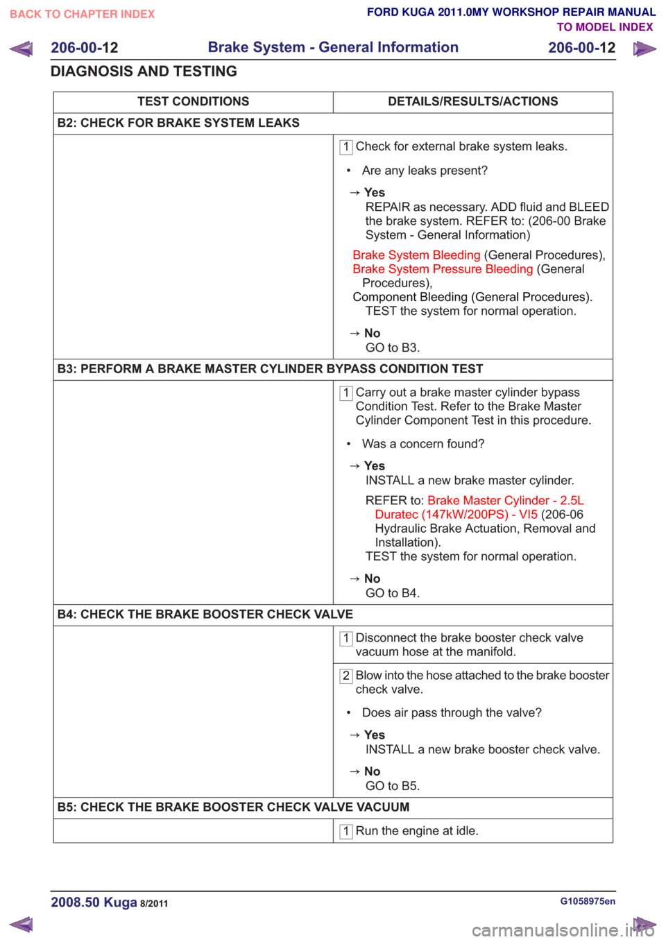
DETAILS/RESULTS/ACTIONS
TEST CONDITIONS
B2: CHECK FOR BRAKE SYSTEM LEAKS
1 Check for external brake system leaks.
• Are any leaks present?
zYe s REPAIR as necessary. ADD fluid and BLEED
the brake system. REFER to: (206-00 Brake
System - General Information)
Brake System Bleeding (General Procedures),
Brake System Pressure Bleeding (General
Procedures),
Component Bleeding (General Procedures).
TEST the system for normal operation.
zNo
GO to B3.
B3: PERFORM A BRAKE MASTER CYLINDER BYPASS CONDITION TEST
1 Carry out a brake master cylinder bypass
Condition Test. Refer to the Brake Master
Cylinder Component Test in this procedure.
• Was a concern found?
zYe s INSTALL a new brake master cylinder.
REFER to: Brake Master Cylinder - 2.5L
Duratec (147kW/200PS) - VI5 (206-06
Hydraulic Brake Actuation, Removal and
Installation).
TEST the system for normal operation.
zNo
GO to B4.
B4: CHECK THE BRAKE BOOSTER CHECK VALVE
1 Disconnect the brake booster check valve
vacuum hose at the manifold.
2Blow into the hose attached to the brake booster
check valve.
• Does air pass through the valve?
zYe s INSTALL a new brake booster check valve.
zNoGO to B5.
B5: CHECK THE BRAKE BOOSTER CHECK VALVE VACUUM
1 Run the engine at idle.
G1058975en2008.50 Kuga8/2011
206-00-
12
Brake System - General Information
206-00- 12
DIAGNOSIS AND TESTING
TO MODEL INDEX
BACK TO CHAPTER INDEX
FORD KUGA 2011.0MY WORKSHOP REPAIR MANUAL
Page 1349 of 2057
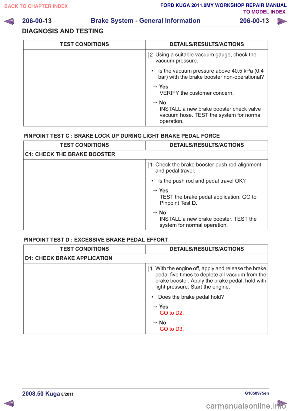
DETAILS/RESULTS/ACTIONS
TEST CONDITIONS
2 Using a suitable vacuum gauge, check the
vacuum pressure.
• Is the vacuum pressure above 40.5 kPa (0.4 bar) with the brake booster non-operational?
zYe s
VERIFY the customer concern.
zNoINSTALL a new brake booster check valve
vacuum hose. TEST the system for normal
operation.
PINPOINT TEST C : BRAKE LOCK UP DURING LIGHT BRAKE PEDAL FORCE
DETAILS/RESULTS/ACTIONS
TEST CONDITIONS
C1: CHECK THE BRAKE BOOSTER
1 Check the brake booster push rod alignment
and pedal travel.
• Is the push rod and pedal travel OK?
zYe s TEST the brake pedal application. GO to
Pinpoint Test D.
zNo
INSTALL a new brake booster. TEST the
system for normal operation.
PINPOINT TEST D : EXCESSIVE BRAKE PEDAL EFFORT
DETAILS/RESULTS/ACTIONS
TEST CONDITIONS
D1: CHECK BRAKE APPLICATION
1 With the engine off, apply and release the brake
pedal five times to deplete all vacuum from the
brake booster. Apply the brake pedal, hold with
light pressure. Start the engine.
• Does the brake pedal hold?
zYe s GO to D2 .
zNo
GO to D3 .
G1058975en2008.50 Kuga8/2011
206-00-13
Brake System - General Information
206-00- 13
DIAGNOSIS AND TESTING
TO MODEL INDEX
BACK TO CHAPTER INDEX
FORD KUGA 2011.0MY WORKSHOP REPAIR MANUAL
Page 1350 of 2057
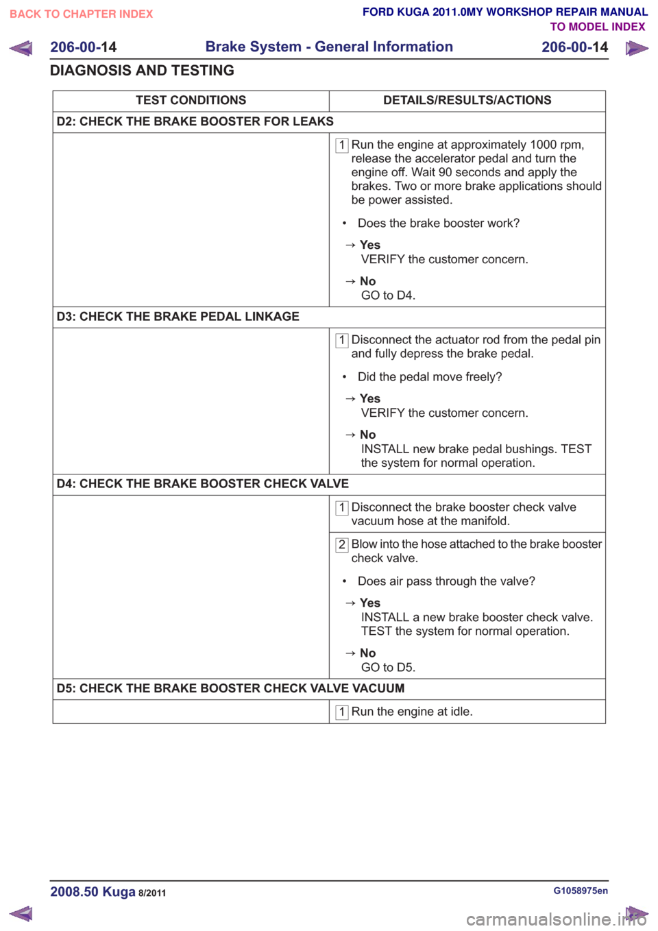
DETAILS/RESULTS/ACTIONS
TEST CONDITIONS
D2: CHECK THE BRAKE BOOSTER FOR LEAKS
1 Run the engine at approximately 1000 rpm,
release the accelerator pedal and turn the
engine off. Wait 90 seconds and apply the
brakes. Two or more brake applications should
be power assisted.
• Does the brake booster work?
zYe s VERIFY the customer concern.
zNoGO to D4 .
D3: CHECK THE BRAKE PEDAL LINKAGE
1 Disconnect the actuator rod from the pedal pin
and fully depress the brake pedal.
• Did the pedal move freely?
zYe s VERIFY the customer concern.
zNoINSTALL new brake pedal bushings. TEST
the system for normal operation.
D4: CHECK THE BRAKE BOOSTER CHECK VALVE
1 Disconnect the brake booster check valve
vacuum hose at the manifold.
2Blow into the hose attached to the brake booster
check valve.
• Does air pass through the valve?
zYe s INSTALL a new brake booster check valve.
TEST the system for normal operation.
zNoGO to D5 .
D5: CHECK THE BRAKE BOOSTER CHECK VALVE VACUUM
1 Run the engine at idle.
G1058975en2008.50 Kuga8/2011
206-00-
14
Brake System - General Information
206-00- 14
DIAGNOSIS AND TESTING
TO MODEL INDEX
BACK TO CHAPTER INDEX
FORD KUGA 2011.0MY WORKSHOP REPAIR MANUAL
Page 1351 of 2057
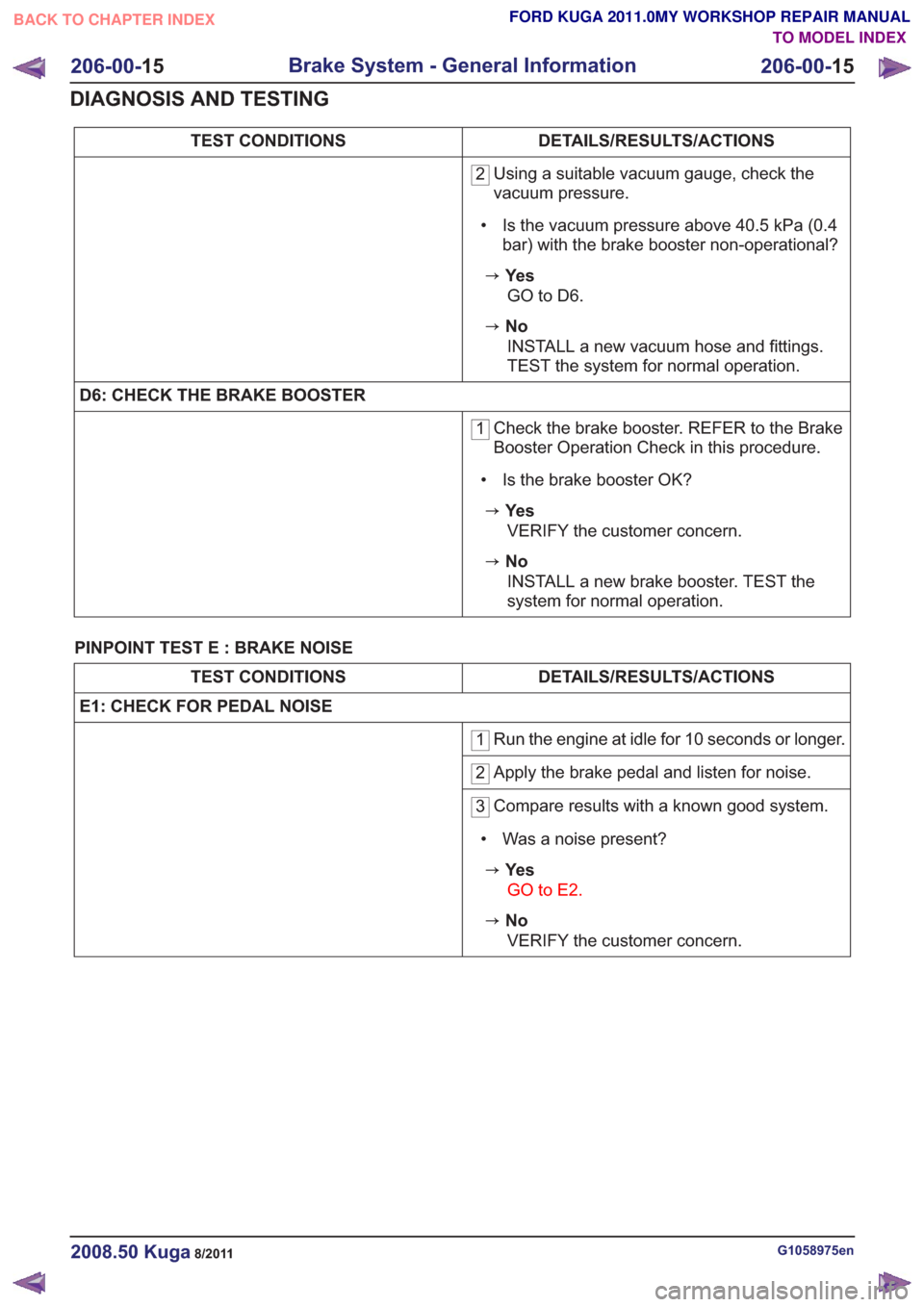
DETAILS/RESULTS/ACTIONS
TEST CONDITIONS
2 Using a suitable vacuum gauge, check the
vacuum pressure.
• Is the vacuum pressure above 40.5 kPa (0.4 bar) with the brake booster non-operational?
zYe s
GO to D6 .
zNo
INSTALL a new vacuum hose and fittings.
TEST the system for normal operation.
D6: CHECK THE BRAKE BOOSTER
1 Check the brake booster. REFER to the Brake
Booster Operation Check in this procedure.
• Is the brake booster OK?
zYe s VERIFY the customer concern.
zNoINSTALL a new brake booster. TEST the
system for normal operation.
PINPOINT TEST E : BRAKE NOISE
DETAILS/RESULTS/ACTIONS
TEST CONDITIONS
E1: CHECK FOR PEDAL NOISE
1 Run the engine at idle for 10 seconds or longer.
2Apply the brake pedal and listen for noise.
3Compare results with a known good system.
• Was a noise present?
zYe s GO to E2.
zNoVERIFY the customer concern.
G1058975en2008.50 Kuga8/2011
206-00- 15
Brake System - General Information
206-00- 15
DIAGNOSIS AND TESTING
TO MODEL INDEX
BACK TO CHAPTER INDEX
FORD KUGA 2011.0MY WORKSHOP REPAIR MANUAL
Page 1352 of 2057
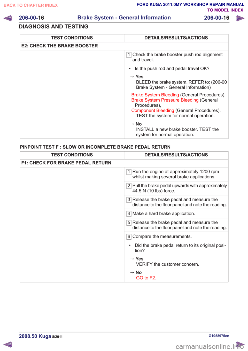
DETAILS/RESULTS/ACTIONS
TEST CONDITIONS
E2: CHECK THE BRAKE BOOSTER
1 Check the brake booster push rod alignment
and travel.
• Is the push rod and pedal travel OK?
zYe s BLEED the brake system. REFER to: (206-00
Brake System - General Information)
Brake System Bleeding (General Procedures),
Brake System Pressure Bleeding (General
Procedures),
Component Bleeding (General Procedures).
TEST the system for normal operation.
zNo
INSTALL a new brake booster. TEST the
system for normal operation.
PINPOINT TEST F : SLOW OR INCOMPLETE BRAKE PEDAL RETURN
DETAILS/RESULTS/ACTIONS
TEST CONDITIONS
F1: CHECK FOR BRAKE PEDAL RETURN
1 Run the engine at approximately 1200 rpm
whilst making several brake applications.
2Pull the brake pedal upwards with approximately
44.5 N (10 lbs) force.
3Release the brake pedal and measure the
distance to the floor panel and note the reading.
4Make a hard brake application.
5Release the brake pedal and measure the
distance to the floor panel and note the reading.
6Compare the measurements.
• Did the brake pedal return to its original posi- tion?
zYe s
VERIFY the customer concern.
zNoGO to F2.
G1058975en2008.50 Kuga8/2011
206-00- 16
Brake System - General Information
206-00- 16
DIAGNOSIS AND TESTING
TO MODEL INDEX
BACK TO CHAPTER INDEX
FORD KUGA 2011.0MY WORKSHOP REPAIR MANUAL
Page 1353 of 2057
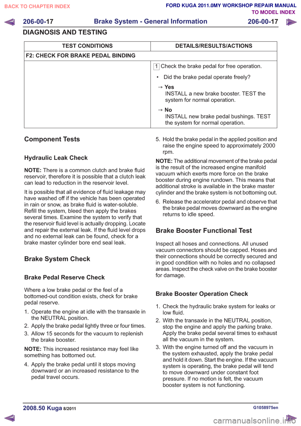
DETAILS/RESULTS/ACTIONS
TEST CONDITIONS
F2: CHECK FOR BRAKE PEDAL BINDING
1 Check the brake pedal for free operation.
• Did the brake pedal operate freely?
zYe s INSTALL a new brake booster. TEST the
system for normal operation.
zNoINSTALL new brake pedal bushings. TEST
the system for normal operation.
Component Tests
Hydraulic Leak Check
NOTE: There is a common clutch and brake fluid
reservoir, therefore it is possible that a clutch leak
can lead to reduction in the reservoir level.
It is possible that all evidence of fluid leakage may
have washed off if the vehicle has been operated
in rain or snow, as brake fluid is water-soluble.
Refill the system, bleed then apply the brakes
several times. Examine the system to verify that
the reservoir fluid level is actually dropping. Locate
and repair the external leak. If the fluid level drops
and no external leak can be found, check for a
brake master cylinder bore end seal leak.
Brake System Check
Brake Pedal Reserve Check
Where a low brake pedal or the feel of a
bottomed-out condition exists, check for brake
pedal reserve.
1. Operate the engine at idle with the transaxle in the NEUTRAL position.
2. Apply the brake pedal lightly three or four times.
3. Allow 15 seconds for the vacuum to replenish the brake booster.
NOTE: This increased resistance may feel like
something has bottomed out.
4. Apply the brake pedal until it stops moving downward or an increased resistance to the
pedal travel occurs. 5. Hold the brake pedal in the applied position and
raise the engine speed to approximately 2000
rpm.
NOTE: The additional movement of the brake pedal
is the result of the increased engine manifold
vacuum which exerts more force on the brake
booster during engine rundown. This means that
additional stroke is available in the brake master
cylinder and the brake system is not bottoming out.
6. Release the accelerator pedal and observe that the brake pedal moves downward as the engine
returns to idle speed.
Brake Booster Functional Test
Inspect all hoses and connections. All unused
vacuum connectors should be capped. Hoses and
their connections should be correctly secured and
in good condition with no holes and no collapsed
areas. Inspect the check valve on the brake booster
for damage.
Brake Booster Operation Check
1. Check the hydraulic brake system for leaks orlow fluid.
2. With the transaxle in the NEUTRAL position, stop the engine and apply the parking brake.
Apply the brake pedal several times to exhaust
all the vacuum in the system.
3. With the engine turned off and the vacuum in the system exhausted, apply the brake pedal
and hold it down. Start the engine. If the vacuum
system is operating, the brake pedal will tend
to move downward under constant foot
pressure. If no motion is felt, the vacuum
booster system is not functioning.
G1058975en2008.50 Kuga8/2011
206-00- 17
Brake System - General Information
206-00- 17
DIAGNOSIS AND TESTING
TO MODEL INDEX
BACK TO CHAPTER INDEX
FORD KUGA 2011.0MY WORKSHOP REPAIR MANUAL