check engine FORD KUGA 2011 1.G Owner's Guide
[x] Cancel search | Manufacturer: FORD, Model Year: 2011, Model line: KUGA, Model: FORD KUGA 2011 1.GPages: 2057
Page 1354 of 2057
4. Remove the vacuum hose from the brakebooster. Manifold vacuum should be available
at the brake booster end of the hose with the
engine at idle speed and the transaxle in the
NEUTRAL position. Make sure that all unused
vacuum outlets are correctly capped, hose
connectors are correctly secured and vacuum
hoses are in good condition. When it is
established that manifold vacuum is available
to the brake booster, connect the vacuum hose
to the brake booster and repeat Step 3. If no
downward movement of the brake pedal is felt,
install a new brake booster.
5. Operate the engine a minimum of 10 seconds at approximately 1200 rpm. Stop the engine and
let the vehicle stand for 10 minutes. Then, apply
the brake pedal with approximately 89 N (20 lb)
force. The pedal feel (brake application) should
be the same as that noted with the engine
operating. If the brake pedal feels hard (no
power assist), install a new vacuum check valve
and then repeat the test. If the brake pedal still
feels hard, install a new brake booster. If the
brake pedal movement feels spongy, bleed the
brake system. REFER to: (206-00 Brake System
- General Information)
Brake System Bleeding (General Procedures),
Brake System Pressure Bleeding (General
Procedures),
Component Bleeding (General Procedures).
Brake Master Cylinder
Usually, the first and strongest indicator of anything
wrong with the braking system is a feeling through
the brake pedal. In diagnosing the condition of the
brake master cylinder, check pedal feel as
evidence of a brake concern. Check for the red
brake warning indicator illumination and the fluid
level in the master cylinder reservoir.
Normal Conditions
The following conditions are considered normal
and are not indications that the brake master
cylinder is in need of service.
– Modern brake systems are not designed to
produce as hard a pedal effort as in the past.
Complaints of light pedal efforts should be compared to pedal efforts of another vehicle, of
the same model and year.
– During normal operation of the brake pedal, the fluid level in the reservoir will rise during brake
pedal application and fall during release. The
net fluid level (i.e., after brake pedal application
and release) will remain unchanged.
– A trace of brake fluid will exists on the brake booster shell below the master cylinder
mounting flange. This results from the normal
lubricating action of the master cylinder bore
end seal.
– The fluid level will fall with brake shoe and lining wear.
Abnormal Conditions
NOTE: Prior to performing any diagnosis, make
sure the brake system warning indicator is
functional.
Changes in brake pedal feel or travel are indicators
that something could be wrong with the braking
system. The diagnostic procedure and techniques
use brake pedal feel, warning indicator illumination
and low brake fluid level as indicators in diagnosing
braking system concerns. The following conditions
are considered abnormal and indicate that the
brake master cylinder is in need of service.
– The brake pedal goes down fast. This could be caused by an external or internal leak.
– The brake pedal eases down slowly. This could be caused by an external or internal leak.
– The brake pedal is low and or feels spongy. This condition may be caused by no fluid in the brake
master cylinder reservoir, reservoir cap vent
holes clogged or air in the hydraulic system.
– The brake pedal effort is excessive. This may be caused by a bind or obstruction in the pedal
or linkage, clogged fluid control valve or
insufficient booster vacuum.
– The rear brakes lock up during light pedal force. This may be caused by incorrect tire pressures,
grease or fluid on the brake shoes and linings,
damaged brake shoes and linings, incorrectly
adjusted parking brake, or damaged or
contaminated brake pressure control valves.
– The brake pedal effort is erratic. This condition could be caused by a brake booster malfunction,
extreme caliper piston knock back or incorrectly
installed brake shoes and linings.
– The red brake warning indicator is ON. This may be caused by low fluid level, ignition wire routing
G1058975en2008.50 Kuga8/2011
206-00- 18
Brake System - General Information
206-00- 18
DIAGNOSIS AND TESTING
TO MODEL INDEX
BACK TO CHAPTER INDEX
FORD KUGA 2011.0MY WORKSHOP REPAIR MANUAL
Page 1429 of 2057
HCU to check for sudden actuation of the brakes.
With the brake pedal pressed, the ABS module
triggers emergency braking if the rate of increase
of hydraulic pressure exceeds the predetermined
limit.
If the brake pedal is pressed so hard that the ABS
becomes active on the front wheels then the ABS
control unit increases the pressure to the rear
wheel brakes up to the ABS intervention threshold.
EBA operation continues until the driver releases
the brake pedal sufficiently for the hydraulic
pressure in the HCU to drop below a threshold
value stored in the ABS module.
Trailer stability control:If the vehicle is ordered
with a trailer coupling then the Trailer Stability
Control function is integrated in the ESP. The ESP
detects snaking when driving with a trailer and
reduces the speed of the vehicle and trailer through
adapted braking and, if necessary, by also reducing
the engine output until the snaking movement of
the trailer is corrected.
Roll-over protection: The ESP dynamically
determines the tipping tendency of the vehicle and
works in conjunction with the EBA system to
prevent the vehicle from tipping over during
dynamic maneuvers like lane changing or while
negotiating bends.
Emergency brake light: The emergency brake
light automatically switches on the hazard flasher
system to warn drivers of other vehicles that
emergency braking is being initiated. Based on a
defined delay value, the ABS/ESP module sends
a signal to the generic electronic module (GEM)
via the CAN data bus. The GEM activates the
hazard flasher system, that then flashes 7 times.
Prerequisites for activation of the emergency brake
light are:
• The speed is higher than 50 km/h.
• The brake pedal is being actuated.
• The deceleration is greater than 9 m/s².
To prevent activation on snow or ice, for example,
the following prerequisites must be met:
• The speed is higher than 50 km/h.
• The brake pedal is being actuated.
• ABS regulation takes place.
• The deceleration is greater than 6 m/s².
Tire pressure monitoring system: The tire
pressure monitoring system used in the Kuga is
able to detect loss of air in a tire at an early stage
and warn the driver. Because it can only compare
the behaviour of the tyres with each other, it is not possible to draw conclusions about the absolute
tyre pressure. It is also not possible to monitor the
spare tyre pressure. In order for the system to
operate correctly, the tyre pressures must be
regularly checked and corrected and the system
subsequently initialised (see below).
The tire pressure monitoring system used here,
depending on the equipment level, is built into the
anti-lock braking system (ABS) as an extra function
and therefore does not have its own sensors.
The ABS module measures the loss of pressure
in the tyres by calculation using the wheel speed
sensors of the ABS system. If a tyre loses
pressure, its diameter decreases and the speed of
the wheel therefore increases. If the ABS module
detects such a loss in pressure, it sends a signal
to the instrument cluster via the CAN bus and a
warning message is displayed in the message
centre. The warning threshold depends among
other things on the dimension of the tyres being
used, the vehicle operating conditions and the
status at the last initialisation. Since neither the
absolute tyre pressure nor the position of the tyre
is known, the pressure of all the tyres must be
checked and the system re-initialised after a tyre
pressure warning. If necessary, the cause of the
loss of pressure must be investigated.
Regular tyre pressure checks are still necessary.
The system must be initialised after a tyre is
changed, winter or summer tyres fitted, the
pressures corrected or adjusted to suit the vehicle
load. This can be done by the driver using the
driver information system. For further information,
see: Owner’s Manual.
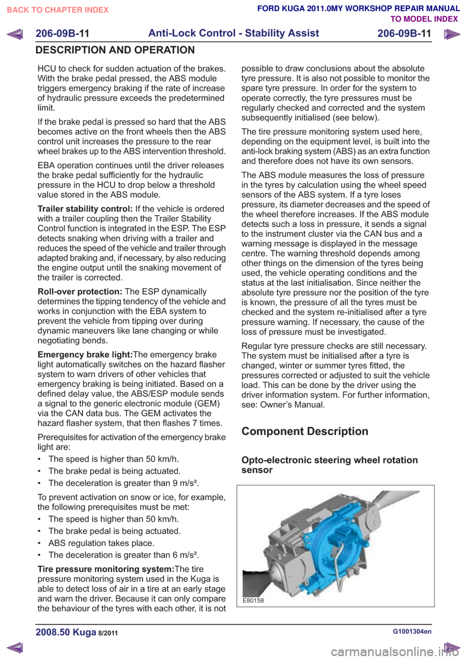
Component Description
Opto-electronic steering wheel rotation
sensor
E80158
G1001304en2008.50 Kuga8/2011
206-09B-
11
Anti-Lock Control - Stability Assist
206-09B- 11
DESCRIPTION AND OPERATION
TO MODEL INDEX
BACK TO CHAPTER INDEX
FORD KUGA 2011.0MY WORKSHOP REPAIR MANUAL
Page 1445 of 2057
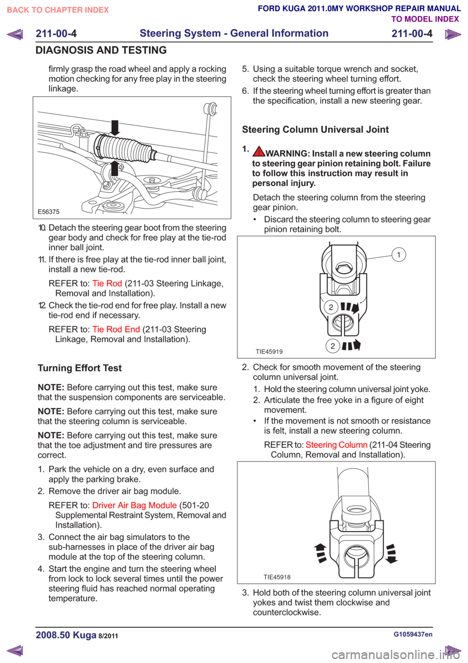
firmly grasp the road wheel and apply a rocking
motion checking for any free play in the steering
linkage.
E56375
10. Detach the steering gear boot from the steeringgear body and check for free play at the tie-rod
inner ball joint.
11. If there is free play at the tie-rod inner ball joint, install a new tie-rod.
REFER to: Tie Rod(211-03 Steering Linkage,
Removal and Installation).
12. Check the tie-rod end for free play. Install a new tie-rod end if necessary.
REFER to: Tie Rod End (211-03 Steering
Linkage, Removal and Installation).
Turning Effort Test
NOTE: Before carrying out this test, make sure
that the suspension components are serviceable.
NOTE: Before carrying out this test, make sure
that the steering column is serviceable.
NOTE: Before carrying out this test, make sure
that the toe adjustment and tire pressures are
correct.
1. Park the vehicle on a dry, even surface and apply the parking brake.
2. Remove the driver air bag module.
REFER to: Driver Air Bag Module (501-20
Supplemental Restraint System, Removal and
Installation).
3. Connect the air bag simulators to the sub-harnesses in place of the driver air bag
module at the top of the steering column.
4. Start the engine and turn the steering wheel from lock to lock several times until the power
steering fluid has reached normal operating
temperature. 5. Using a suitable torque wrench and socket,
check the steering wheel turning effort.
6. If the steering wheel turning effort is greater than the specification, install a new steering gear.
Steering Column Universal Joint
1.WARNING: Install a new steering column
to steering gear pinion retaining bolt. Failure
to follow this instruction may result in
personal injury.
Detach the steering column from the steering
gear pinion.• Discard the steering column to steering gear pinion retaining bolt.
TIE45919
1
2
2
2. Check for smooth movement of the steeringcolumn universal joint.
1. Hold the steering column universal joint yoke.
2. Articulate the free yoke in a figure of eight movement.
• If the movement is not smooth or resistance is felt, install a new steering column.
REFER to: Steering Column (211-04 Steering
Column, Removal and Installation).
TIE45918
3. Hold both of the steering column universal joint yokes and twist them clockwise and
counterclockwise.
G1059437en2008.50 Kuga8/2011
211-00- 4
Steering System - General Information
211-00- 4
DIAGNOSIS AND TESTING
TO MODEL INDEX
BACK TO CHAPTER INDEX
FORD KUGA 2011.0MY WORKSHOP REPAIR MANUAL
Page 1447 of 2057
Steering Gear Checks After a Collision
General EquipmentFeeler gauge
Straight edge
Items to be observed when checking the steering
system
The following list of steering gear conditions and
the methods of testing should be taken into account
when carrying out checks to the steering system:
• If the steering gear has no faults after completing the following checks, do not install
a new steering gear.
• Surface corrosion and marks on the tie-rod are acceptable.
• When checking for turning effort torque peaks in the steering gear, turn the steering wheel from
steering lock stop to steering lock stop in
approximately 15 seconds.
• A steady increase of turning effort torque from steering center to steering lock stop is
acceptable.
• When checking for power steering fluid leaks, turn the steering wheel to the steering lock stop
in approximately 10 seconds.
• Noises from the power steering, for example the power steering pump relief valve, are
acceptable.
STEERING GEAR HOUSING
1. Raise and support the vehicle. REFER to: Lifting(100-02 Jacking and Lifting,
Description and Operation).
2. Visually inspect the steering gear housing for cracks and damage. If the steering gear housing
is cracked or damaged, install a new steering
gear.
REFER to: Steering Gear (211-02 Power
Steering, Removal and Installation).
TIE-RODS
1. Using a straight edge and feeler gauge, check the tie-rods to see if they are straight. If the
distance between the tie-rod and straight edge is greater than 0.5 mm, install a new steering
gear.
REFER to:
Steering Gear (211-02 Power
Steering, Removal and Installation).
2. Check the tightening torque of the tie-rod end to wheel knuckle nut.
REFER to: Tie Rod End (211-03 Steering
Linkage, Removal and Installation).
3. Check the tightening torque of the tie-rod end locking nut.
REFER to: Tie Rod End (211-03 Steering
Linkage, Removal and Installation).
CHECK FOR TURNING EFFORT TORQUE
PEAKS IN THE STEERING GEAR
1. Lower and support the vehicle making sure that the road wheels are just clear of the floor.
2. With the ignition switch in position I, slowly turn the steering wheel from steering lock stop to
steering lock stop. If a turning effort torque peak
or judder is felt while turning the steering wheel,
detach the tie-rods from the wheel knuckles.
3. Slowly turn the steering wheel from steering lock stop to steering lock stop. If a turning effort
torque peak or judder is felt while turning the
steering wheel, install a new steering gear.
REFER to: Steering Gear (211-02 Power
Steering, Removal and Installation).
CHECK FOR POWER STEERING FLUID LEAKS
1. Lower the vehicle.
2. Run the engine at a fast idle and slowly turn the steering wheel to the left-hand steering lock
stop. Hold the steering wheel in this position for
5 seconds with a turning effort torque of 15 Nm
at the steering wheel rim.
3. Turn the steering wheel away from the left-hand steering lock stop for 30 seconds.
4. Run the engine at a fast idle and slowly turn the steering wheel to the right-hand steering lock
stop. Hold the steering wheel in this position for
5 seconds with a turning effort torque of 15 Nm
at the steering wheel rim.
5. Turn the steering wheel away from the right-hand steering lock stop.
6. Check for power steering fluid leaks at the steering gear housing and the power steering
line connections to the steering gear. If there is
G538091en2008.50 Kuga8/2011
211-00- 6
Steering System - General Information
211-00- 6
DIAGNOSIS AND TESTING
TO MODEL INDEX
BACK TO CHAPTER INDEX
FORD KUGA 2011.0MY WORKSHOP REPAIR MANUAL
Page 1450 of 2057
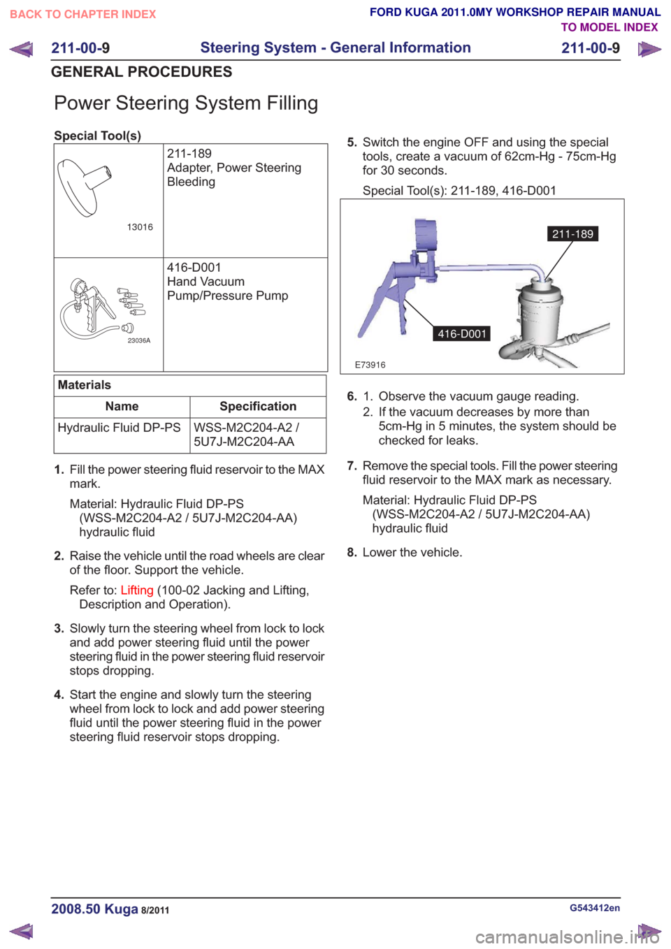
Power Steering System Filling
Special Tool(s)211-189
Adapter, Power Steering
Bleeding
13016
416-D001
Hand Vacuum
Pump/Pressure Pump
23036A
Materials
Specification
Name
WSS-M2C204-A2 /
5U7J-M2C204-AA
Hydraulic Fluid DP-PS
1. Fill the power steering fluid reservoir to the MAX
mark.
Material: Hydraulic Fluid DP-PS
(WSS-M2C204-A2 / 5U7J-M2C204-AA)
hydraulic fluid
2. Raise the vehicle until the road wheels are clear
of the floor. Support the vehicle.
Refer to: Lifting(100-02 Jacking and Lifting,
Description and Operation).
3. Slowly turn the steering wheel from lock to lock
and add power steering fluid until the power
steering fluid in the power steering fluid reservoir
stops dropping.
4. Start the engine and slowly turn the steering
wheel from lock to lock and add power steering
fluid until the power steering fluid in the power
steering fluid reservoir stops dropping. 5.
Switch the engine OFF and using the special
tools, create a vacuum of 62cm-Hg - 75cm-Hg
for 30 seconds.
Special Tool(s): 211-189, 416-D001
E73916
211-189
416-D001
6. Observe the vacuum gauge reading.
1.
2. If the vacuum decreases by more than
5cm-Hg in 5 minutes, the system should be
checked for leaks.
7. Remove the special tools. Fill the power steering
fluid reservoir to the MAX mark as necessary.
Material: Hydraulic Fluid DP-PS
(WSS-M2C204-A2 / 5U7J-M2C204-AA)
hydraulic fluid
8. Lower the vehicle.
G543412en2008.50 Kuga8/2011
211-00- 9
Steering System - General Information
211-00- 9
GENERAL PROCEDURES
TO MODEL INDEX
BACK TO CHAPTER INDEX
FORD KUGA 2011.0MY WORKSHOP REPAIR MANUAL
Page 1518 of 2057
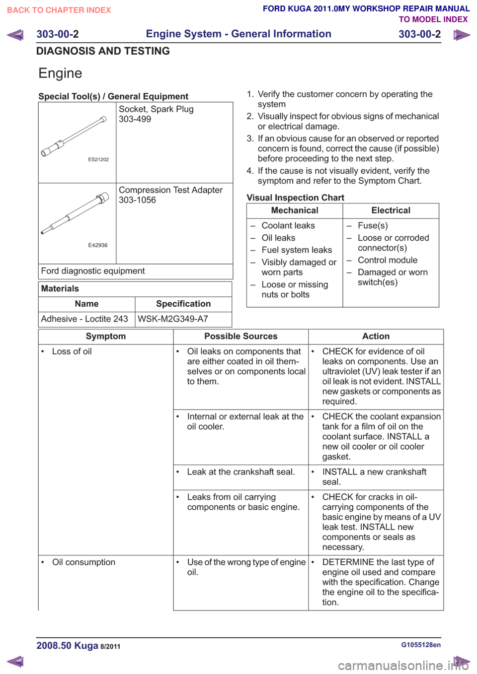
Engine
Special Tool(s) / General EquipmentSocket, Spark Plug
303-499
ES21202
Compression Test Adapter
303-1056
E42936
Ford diagnostic equipment
Materials
Specification
Name
WSK-M2G349-A7
Adhesive - Loctite 243 1. Verify the customer concern by operating the
system
2. Visually inspect for obvious signs of mechanical or electrical damage.
3. If an obvious cause for an observed or reported concern is found, correct the cause (if possible)
before proceeding to the next step.
4. If the cause is not visually evident, verify the symptom and refer to the Symptom Chart.
Visual Inspection Chart
Electrical
Mechanical
– Fuse(s)
– Loose or corrodedconnector(s)
– Control module
– Damaged or worn switch(es)
– Coolant leaks
– Oil leaks
– Fuel system leaks
– Visibly damaged or
worn parts
– Loose or missing nuts or bolts
Action
Possible Sources
Symptom
• CHECK for evidence of oilleaks on components. Use an
ultraviolet (UV) leak tester if an
oil leak is not evident. INSTALL
new gaskets or components as
required.
• Oil leaks on components that
are either coated in oil them-
selves or on components local
to them.
• Loss of oil
• CHECK the coolant expansiontank for a film of oil on the
coolant surface. INSTALL a
new oil cooler or oil cooler
gasket.
• Internal or external leak at the
oil cooler.
• INSTALL a new crankshaftseal.
• Leak at the crankshaft seal.
• CHECK for cracks in oil-carrying components of the
basic engine by means of a UV
leak test. INSTALL new
components or seals as
necessary.
• Leaks from oil carrying
components or basic engine.
• DETERMINE the last type ofengine oil used and compare
with the specification. Change
the engine oil to the specifica-
tion.
• Use of the wrong type of engine
oil.
• Oil consumption
G1055128en2008.50 Kuga8/2011
303-00-
2
Engine System - General Information
303-00- 2
DIAGNOSIS AND TESTING
TO MODEL INDEX
BACK TO CHAPTER INDEX
FORD KUGA 2011.0MY WORKSHOP REPAIR MANUAL
Page 1519 of 2057
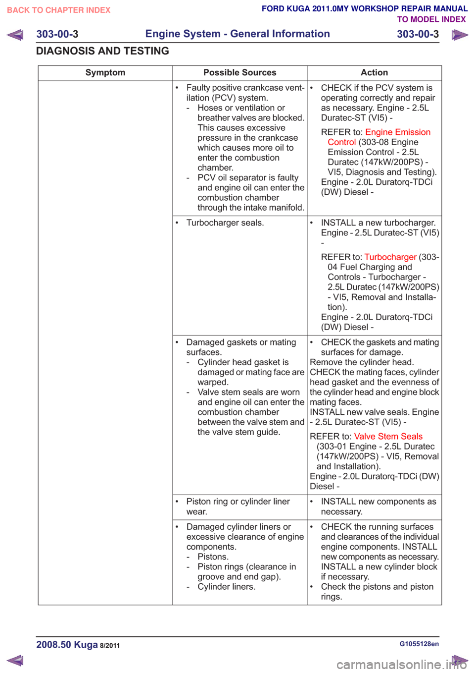
Action
Possible Sources
Symptom
• CHECK if the PCV system isoperating correctly and repair
as necessary. Engine - 2.5L
Duratec-ST (VI5) -
REFER to: Engine Emission
Control (303-08 Engine
Emission Control - 2.5L
Duratec (147kW/200PS) -
VI5, Diagnosis and Testing).
Engine - 2.0L Duratorq-TDCi
(DW) Diesel -
• Faulty positive crankcase vent-
ilation (PCV) system.
- Hoses or ventilation orbreather valves are blocked.
This causes excessive
pressure in the crankcase
which causes more oil to
enter the combustion
chamber.
- PCV oil separator is faulty and engine oil can enter the
combustion chamber
through the intake manifold.
• INSTALL a new turbocharger.Engine - 2.5L Duratec-ST (VI5)
-
REFER to: Turbocharger (303-
04 Fuel Charging and
Controls - Turbocharger -
2.5L Duratec (147kW/200PS)
- VI5, Removal and Installa-
tion).
Engine - 2.0L Duratorq-TDCi
(DW) Diesel -
• Turbocharger seals.
• CHECK the gaskets and matingsurfaces for damage.
Remove the cylinder head.
CHECK the mating faces, cylinder
head gasket and the evenness of
the cylinder head and engine block
mating faces.
INSTALL new valve seals. Engine
- 2.5L Duratec-ST (VI5) -
REFER to: Valve Stem Seals
(303-01 Engine - 2.5L Duratec
(147kW/200PS) - VI5, Removal
and Installation).
Engine - 2.0L Duratorq-TDCi (DW)
Diesel -
• Damaged gaskets or mating
surfaces.
- Cylinder head gasket isdamaged or mating face are
warped.
- Valve stem seals are worn and engine oil can enter the
combustion chamber
between the valve stem and
the valve stem guide.
• INSTALL new components asnecessary.
• Piston ring or cylinder liner
wear.
• CHECK the running surfacesand clearances of the individual
engine components. INSTALL
new components as necessary.
INSTALL a new cylinder block
if necessary.
• Check the pistons and piston rings.
• Damaged cylinder liners or
excessive clearance of engine
components.
- Pistons.
- Piston rings (clearance ingroove and end gap).
- Cylinder liners.
G1055128en2008.50 Kuga8/2011
303-00- 3
Engine System - General Information
303-00- 3
DIAGNOSIS AND TESTING
TO MODEL INDEX
BACK TO CHAPTER INDEX
FORD KUGA 2011.0MY WORKSHOP REPAIR MANUAL
Page 1520 of 2057
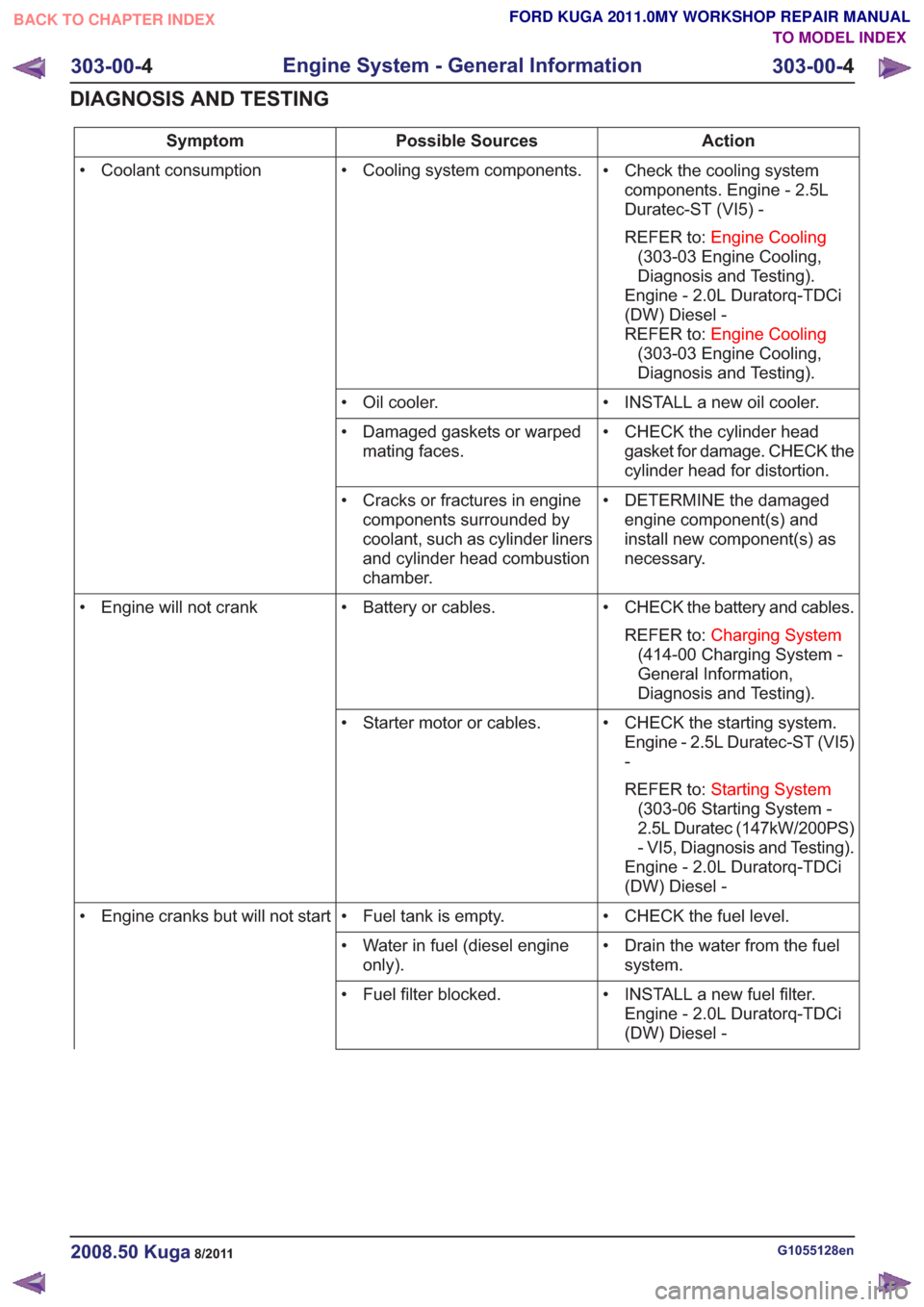
Action
Possible Sources
Symptom
• Check the cooling systemcomponents. Engine - 2.5L
Duratec-ST (VI5) -
REFER to: Engine Cooling
(303-03 Engine Cooling,
Diagnosis and Testing).
Engine - 2.0L Duratorq-TDCi
(DW) Diesel -
REFER to: Engine Cooling
(303-03 Engine Cooling,
Diagnosis and Testing).
• Cooling system components.
• Coolant consumption
• INSTALL a new oil cooler.
• Oil cooler.
• CHECK the cylinder headgasket for damage. CHECK the
cylinder head for distortion.
• Damaged gaskets or warped
mating faces.
• DETERMINE the damagedengine component(s) and
install new component(s) as
necessary.
• Cracks or fractures in engine
components surrounded by
coolant, such as cylinder liners
and cylinder head combustion
chamber.
• CHECK the battery and cables.REFER to: Charging System
(414-00 Charging System -
General Information,
Diagnosis and Testing).
• Battery or cables.
• Engine will not crank
• CHECK the starting system.Engine - 2.5L Duratec-ST (VI5)
-
REFER to: Starting System
(303-06 Starting System -
2.5L Duratec (147kW/200PS)
- VI5, Diagnosis and Testing).
Engine - 2.0L Duratorq-TDCi
(DW) Diesel -
• Starter motor or cables.
• CHECK the fuel level.
• Fuel tank is empty.
• Engine cranks but will not start
• Drain the water from the fuelsystem.
• Water in fuel (diesel engine
only).
• INSTALL a new fuel filter.Engine - 2.0L Duratorq-TDCi
(DW) Diesel -
• Fuel filter blocked.
G1055128en2008.50 Kuga8/2011
303-00-
4
Engine System - General Information
303-00- 4
DIAGNOSIS AND TESTING
TO MODEL INDEX
BACK TO CHAPTER INDEX
FORD KUGA 2011.0MY WORKSHOP REPAIR MANUAL
Page 1521 of 2057
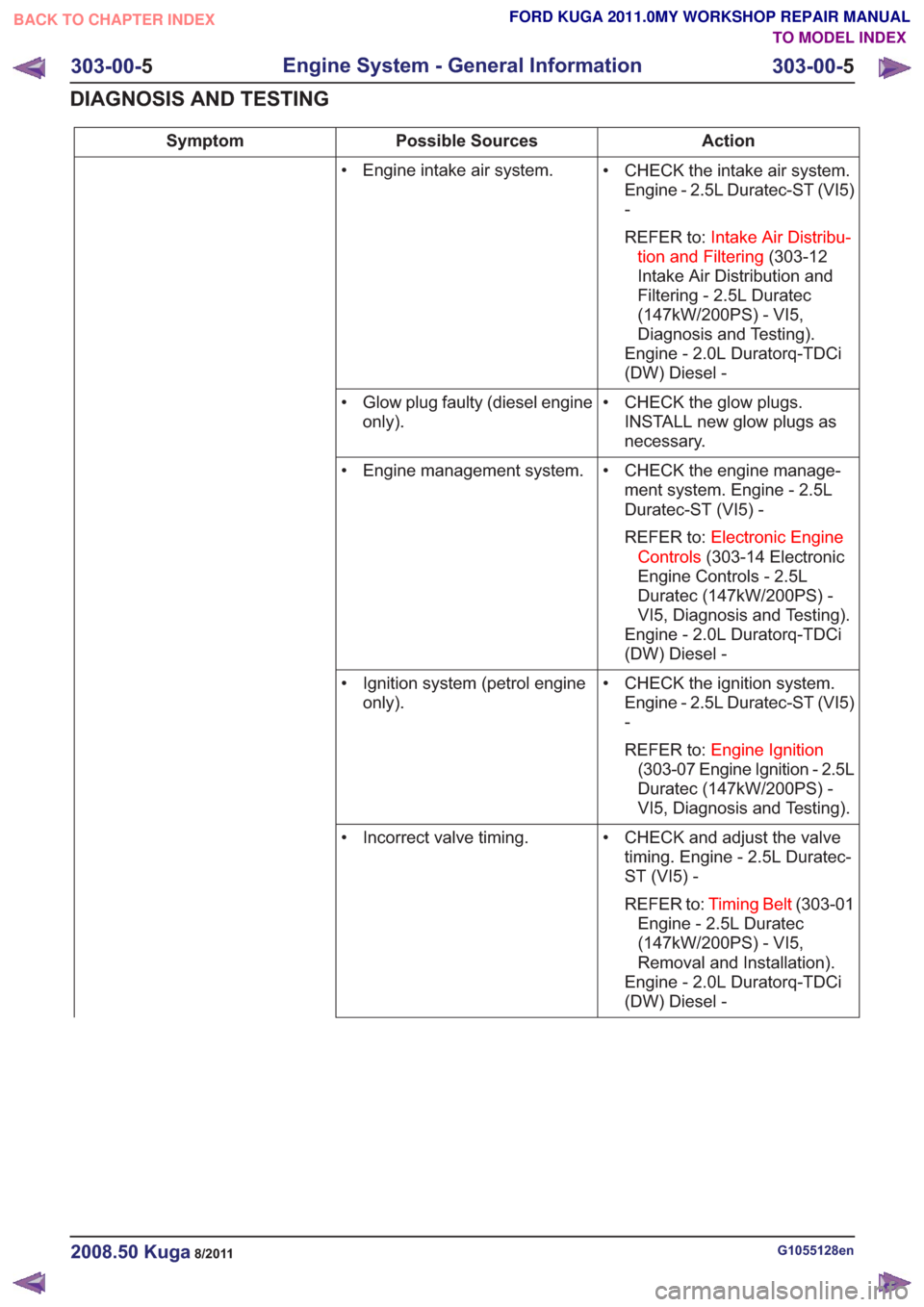
Action
Possible Sources
Symptom
• CHECK the intake air system.Engine - 2.5L Duratec-ST (VI5)
-
REFER to: Intake Air Distribu-
tion and Filtering (303-12
Intake Air Distribution and
Filtering - 2.5L Duratec
(147kW/200PS) - VI5,
Diagnosis and Testing).
Engine - 2.0L Duratorq-TDCi
(DW) Diesel -
• Engine intake air system.
• CHECK the glow plugs.INSTALL new glow plugs as
necessary.
• Glow plug faulty (diesel engine
only).
• CHECK the engine manage-ment system. Engine - 2.5L
Duratec-ST (VI5) -
REFER to: Electronic Engine
Controls (303-14 Electronic
Engine Controls - 2.5L
Duratec (147kW/200PS) -
VI5, Diagnosis and Testing).
Engine - 2.0L Duratorq-TDCi
(DW) Diesel -
• Engine management system.
• CHECK the ignition system.Engine - 2.5L Duratec-ST (VI5)
-
REFER to: Engine Ignition
(303-07 Engine Ignition - 2.5L
Duratec (147kW/200PS) -
VI5, Diagnosis and Testing).
• Ignition system (petrol engine
only).
• CHECK and adjust the valvetiming. Engine - 2.5L Duratec-
ST (VI5) -
REFER to: Timing Belt (303-01
Engine - 2.5L Duratec
(147kW/200PS) - VI5,
Removal and Installation).
Engine - 2.0L Duratorq-TDCi
(DW) Diesel -
• Incorrect valve timing.
G1055128en2008.50 Kuga8/2011
303-00-
5
Engine System - General Information
303-00- 5
DIAGNOSIS AND TESTING
TO MODEL INDEX
BACK TO CHAPTER INDEX
FORD KUGA 2011.0MY WORKSHOP REPAIR MANUAL
Page 1522 of 2057
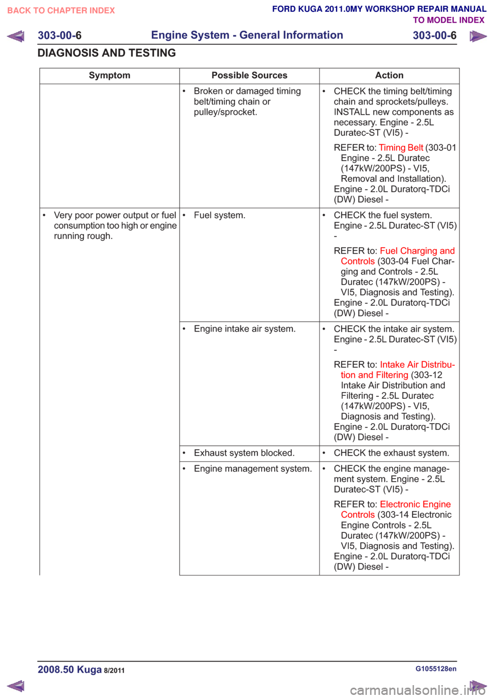
Action
Possible Sources
Symptom
• CHECK the timing belt/timingchain and sprockets/pulleys.
INSTALL new components as
necessary. Engine - 2.5L
Duratec-ST (VI5) -
REFER to: Timing Belt (303-01
Engine - 2.5L Duratec
(147kW/200PS) - VI5,
Removal and Installation).
Engine - 2.0L Duratorq-TDCi
(DW) Diesel -
• Broken or damaged timing
belt/timing chain or
pulley/sprocket.
• CHECK the fuel system.Engine - 2.5L Duratec-ST (VI5)
-
REFER to: Fuel Charging and
Controls (303-04 Fuel Char-
ging and Controls - 2.5L
Duratec (147kW/200PS) -
VI5, Diagnosis and Testing).
Engine - 2.0L Duratorq-TDCi
(DW) Diesel -
• Fuel system.
• Very poor power output or fuel
consumption too high or engine
running rough.
• CHECK the intake air system.Engine - 2.5L Duratec-ST (VI5)
-
REFER to: Intake Air Distribu-
tion and Filtering (303-12
Intake Air Distribution and
Filtering - 2.5L Duratec
(147kW/200PS) - VI5,
Diagnosis and Testing).
Engine - 2.0L Duratorq-TDCi
(DW) Diesel -
• Engine intake air system.
• CHECK the exhaust system.
• Exhaust system blocked.
• CHECK the engine manage-ment system. Engine - 2.5L
Duratec-ST (VI5) -
REFER to: Electronic Engine
Controls (303-14 Electronic
Engine Controls - 2.5L
Duratec (147kW/200PS) -
VI5, Diagnosis and Testing).
Engine - 2.0L Duratorq-TDCi
(DW) Diesel -
• Engine management system.
G1055128en2008.50 Kuga8/2011
303-00-
6
Engine System - General Information
303-00- 6
DIAGNOSIS AND TESTING
TO MODEL INDEX
BACK TO CHAPTER INDEX
FORD KUGA 2011.0MY WORKSHOP REPAIR MANUAL