spring FORD KUGA 2011 1.G Repair Manual
[x] Cancel search | Manufacturer: FORD, Model Year: 2011, Model line: KUGA, Model: FORD KUGA 2011 1.GPages: 2057
Page 1724 of 2057
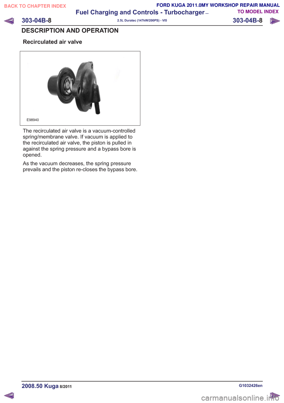
Recirculated air valve
E98940
The recirculated air valve is a vacuum-controlled
spring/membrane valve. If vacuum is applied to
the recirculated air valve, the piston is pulled in
against the spring pressure and a bypass bore is
opened.
As the vacuum decreases, the spring pressure
prevails and the piston re-closes the bypass bore.
G1032426en2008.50 Kuga8/2011
303-04B-8
Fuel Charging and Controls - Turbocharger
—
2.5L Duratec (147kW/200PS) - VI5
303-04B- 8
DESCRIPTION AND OPERATION
TO MODEL INDEX
BACK TO CHAPTER INDEX
FORD KUGA 2011.0MY WORKSHOP REPAIR MANUAL
Page 1739 of 2057
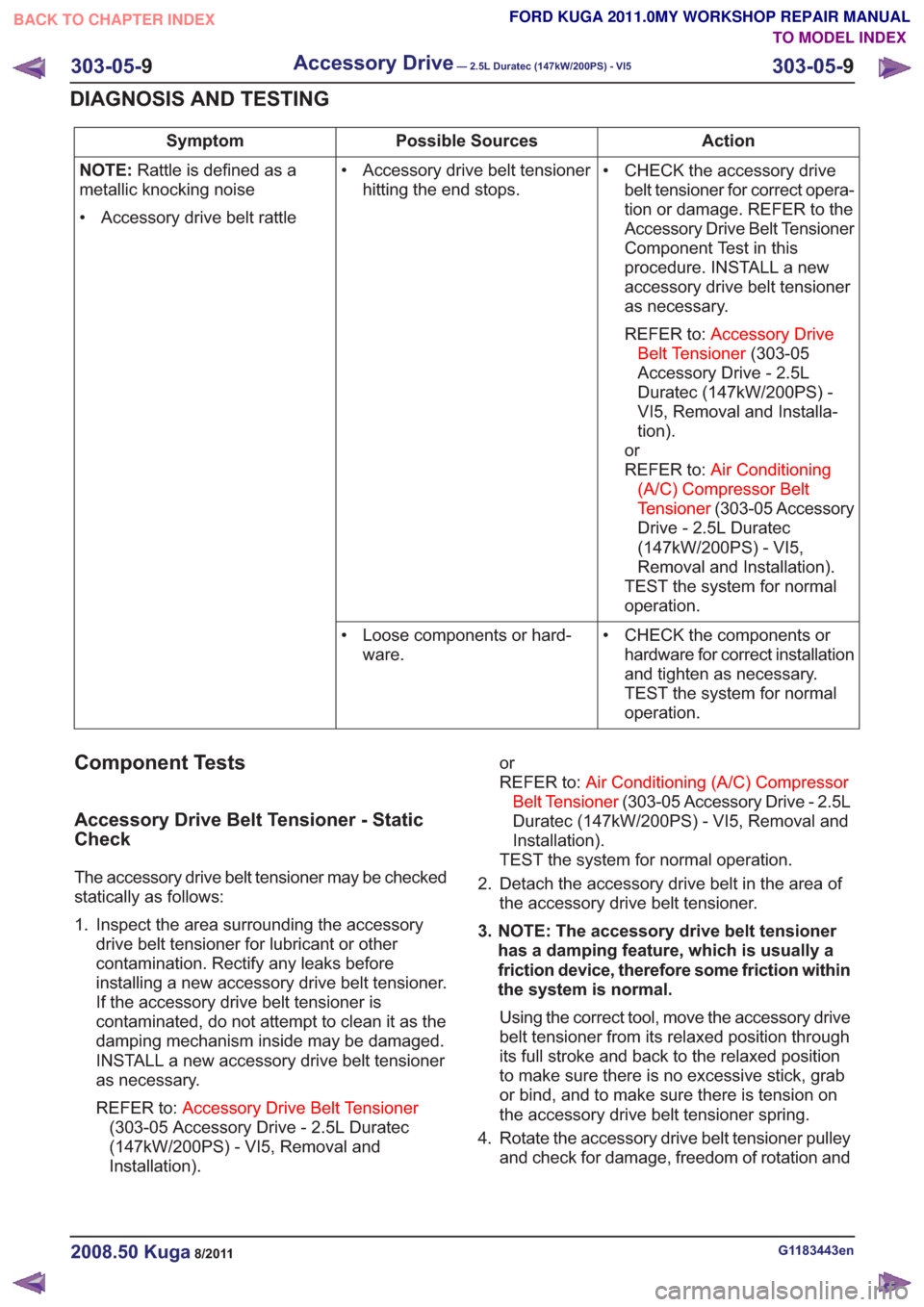
Action
Possible Sources
Symptom
• CHECK the accessory drivebelt tensioner for correct opera-
tion or damage. REFER to the
Accessory Drive Belt Tensioner
Component Test in this
procedure. INSTALL a new
accessory drive belt tensioner
as necessary.
REFER to: Accessory Drive
Belt Tensioner (303-05
Accessory Drive - 2.5L
Duratec (147kW/200PS) -
VI5, Removal and Installa-
tion).
or
REFER to: Air Conditioning
(A/C) Compressor Belt
Tensioner (303-05 Accessory
Drive - 2.5L Duratec
(147kW/200PS) - VI5,
Removal and Installation).
TEST the system for normal
operation.
• Accessory drive belt tensioner
hitting the end stops.
NOTE:
Rattle is defined as a
metallic knocking noise
• Accessory drive belt rattle
• CHECK the components orhardware for correct installation
and tighten as necessary.
TEST the system for normal
operation.
• Loose components or hard-
ware.
Component Tests
Accessory Drive Belt Tensioner - Static
Check
The accessory drive belt tensioner may be checked
statically as follows:
1. Inspect the area surrounding the accessorydrive belt tensioner for lubricant or other
contamination. Rectify any leaks before
installing a new accessory drive belt tensioner.
If the accessory drive belt tensioner is
contaminated, do not attempt to clean it as the
damping mechanism inside may be damaged.
INSTALL a new accessory drive belt tensioner
as necessary.
REFER to: Accessory Drive Belt Tensioner
(303-05 Accessory Drive - 2.5L Duratec
(147kW/200PS) - VI5, Removal and
Installation). or
REFER to:
Air Conditioning (A/C) Compressor
Belt Tensioner (303-05 Accessory Drive - 2.5L
Duratec (147kW/200PS) - VI5, Removal and
Installation).
TEST the system for normal operation.
2. Detach the accessory drive belt in the area of the accessory drive belt tensioner.
3. NOTE: The accessory drive belt tensioner has a damping feature, which is usually a
friction device, therefore some friction within
the system is normal.
Using the correct tool, move the accessory drive
belt tensioner from its relaxed position through
its full stroke and back to the relaxed position
to make sure there is no excessive stick, grab
or bind, and to make sure there is tension on
the accessory drive belt tensioner spring.
4. Rotate the accessory drive belt tensioner pulley and check for damage, freedom of rotation and
G1183443en2008.50 Kuga8/2011
303-05- 9
Accessory Drive— 2.5L Duratec (147kW/200PS) - VI5303-05-
9
DIAGNOSIS AND TESTING
TO MODEL INDEX
BACK TO CHAPTER INDEX
FORD KUGA 2011.0MY WORKSHOP REPAIR MANUAL
Page 1796 of 2057
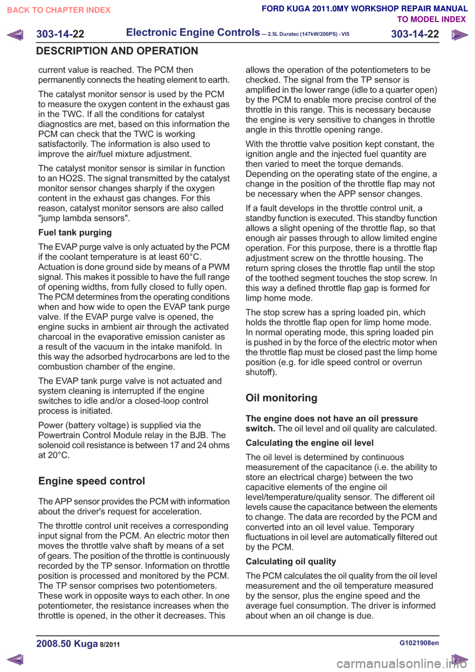
current value is reached. The PCM then
permanently connects the heating element to earth.
The catalyst monitor sensor is used by the PCM
to measure the oxygen content in the exhaust gas
in the TWC. If all the conditions for catalyst
diagnostics are met, based on this information the
PCM can check that the TWC is working
satisfactorily. The information is also used to
improve the air/fuel mixture adjustment.
The catalyst monitor sensor is similar in function
to an HO2S. The signal transmitted by the catalyst
monitor sensor changes sharply if the oxygen
content in the exhaust gas changes. For this
reason, catalyst monitor sensors are also called
"jump lambda sensors".
Fuel tank purging
The EVAP purge valve is only actuated by the PCM
if the coolant temperature is at least 60°C.
Actuation is done ground side by means of a PWM
signal. This makes it possible to have the full range
of opening widths, from fully closed to fully open.
The PCM determines from the operating conditions
when and how wide to open the EVAP tank purge
valve. If the EVAP purge valve is opened, the
engine sucks in ambient air through the activated
charcoal in the evaporative emission canister as
a result of the vacuum in the intake manifold. In
this way the adsorbed hydrocarbons are led to the
combustion chamber of the engine.
The EVAP tank purge valve is not actuated and
system cleaning is interrupted if the engine
switches to idle and/or a closed-loop control
process is initiated.
Power (battery voltage) is supplied via the
Powertrain Control Module relay in the BJB. The
solenoid coil resistance is between 17 and 24 ohms
at 20°C.
Engine speed control
The APP sensor provides the PCM with information
about the driver's request for acceleration.
The throttle control unit receives a corresponding
input signal from the PCM. An electric motor then
moves the throttle valve shaft by means of a set
of gears. The position of the throttle is continuously
recorded by the TP sensor. Information on throttle
position is processed and monitored by the PCM.
The TP sensor comprises two potentiometers.
These work in opposite ways to each other. In one
potentiometer, the resistance increases when the
throttle is opened, in the other it decreases. Thisallows the operation of the potentiometers to be
checked. The signal from the TP sensor is
amplified in the lower range (idle to a quarter open)
by the PCM to enable more precise control of the
throttle in this range. This is necessary because
the engine is very sensitive to changes in throttle
angle in this throttle opening range.
With the throttle valve position kept constant, the
ignition angle and the injected fuel quantity are
then varied to meet the torque demands.
Depending on the operating state of the engine, a
change in the position of the throttle flap may not
be necessary when the APP sensor changes.
If a fault develops in the throttle control unit, a
standby function is executed. This standby function
allows a slight opening of the throttle flap, so that
enough air passes through to allow limited engine
operation. For this purpose, there is a throttle flap
adjustment screw on the throttle housing. The
return spring closes the throttle flap until the stop
of the toothed segment touches the stop screw. In
this way a defined throttle flap gap is formed for
limp home mode.
The stop screw has a spring loaded pin, which
holds the throttle flap open for limp home mode.
In normal operating mode, this spring loaded pin
is pushed in by the force of the electric motor when
the throttle flap must be closed past the limp home
position (e.g. for idle speed control or overrun
shutoff).
Oil monitoring
The engine does not have an oil pressure
switch.
The oil level and oil quality are calculated.
Calculating the engine oil level
The oil level is determined by continuous
measurement of the capacitance (i.e. the ability to
store an electrical charge) between the two
capacitive elements of the engine oil
level/temperature/quality sensor. The different oil
levels cause the capacitance between the elements
to change. The data are recorded by the PCM and
converted into an oil level value. Temporary
fluctuations in oil level are automatically filtered out
by the PCM.
Calculating oil quality
The PCM calculates the oil quality from the oil level
measurement and the oil temperature measured
by the sensor, plus the engine speed and the
average fuel consumption. The driver is informed
about when an oil change is due.
G1021908en2008.50 Kuga8/2011
303-14- 22
Electronic Engine Controls— 2.5L Duratec (147kW/200PS) - VI5303-14-
22
DESCRIPTION AND OPERATION
TO MODEL INDEX
BACK TO CHAPTER INDEX
FORD KUGA 2011.0MY WORKSHOP REPAIR MANUAL
Page 1801 of 2057
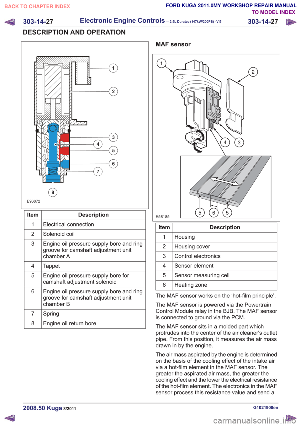
E96872
1
2
3
5
4
6
7
8
Description
Item
Electrical connection
1
Solenoid coil
2
Engine oil pressure supply bore and ring
groove for camshaft adjustment unit
chamber A
3
Tappet
4
Engine oil pressure supply bore for
camshaft adjustment solenoid
5
Engine oil pressure supply bore and ring
groove for camshaft adjustment unit
chamber B
6
Spring
7
Engine oil return bore
8
MAF sensor
E58185
1
2
43
565
Description
Item
Housing
1
Housing cover
2
Control electronics
3
Sensor element
4
Sensor measuring cell
5
Heating zone
6
The MAF sensor works on the ‘hot-film principle’.
The MAF sensor is powered via the Powertrain
Control Module relay in the BJB. The MAF sensor
is connected to ground via the PCM.
The MAF sensor sits in a molded part which
protrudes into the center of the air cleaner's outlet
pipe. From this position, it measures the air mass
drawn in by the engine.
The air mass aspirated by the engine is determined
on the basis of the cooling effect of the intake air
via a hot-film element in the MAF sensor. The
greater the aspirated air mass, the greater the
cooling effect and the lower the electrical resistance
of the hot-film element. The electronics in the MAF
sensor process this resistance value and send a
G1021908en2008.50 Kuga8/2011
303-14- 27
Electronic Engine Controls— 2.5L Duratec (147kW/200PS) - VI5303-14-
27
DESCRIPTION AND OPERATION
TO MODEL INDEX
BACK TO CHAPTER INDEX
FORD KUGA 2011.0MY WORKSHOP REPAIR MANUAL
Page 1805 of 2057
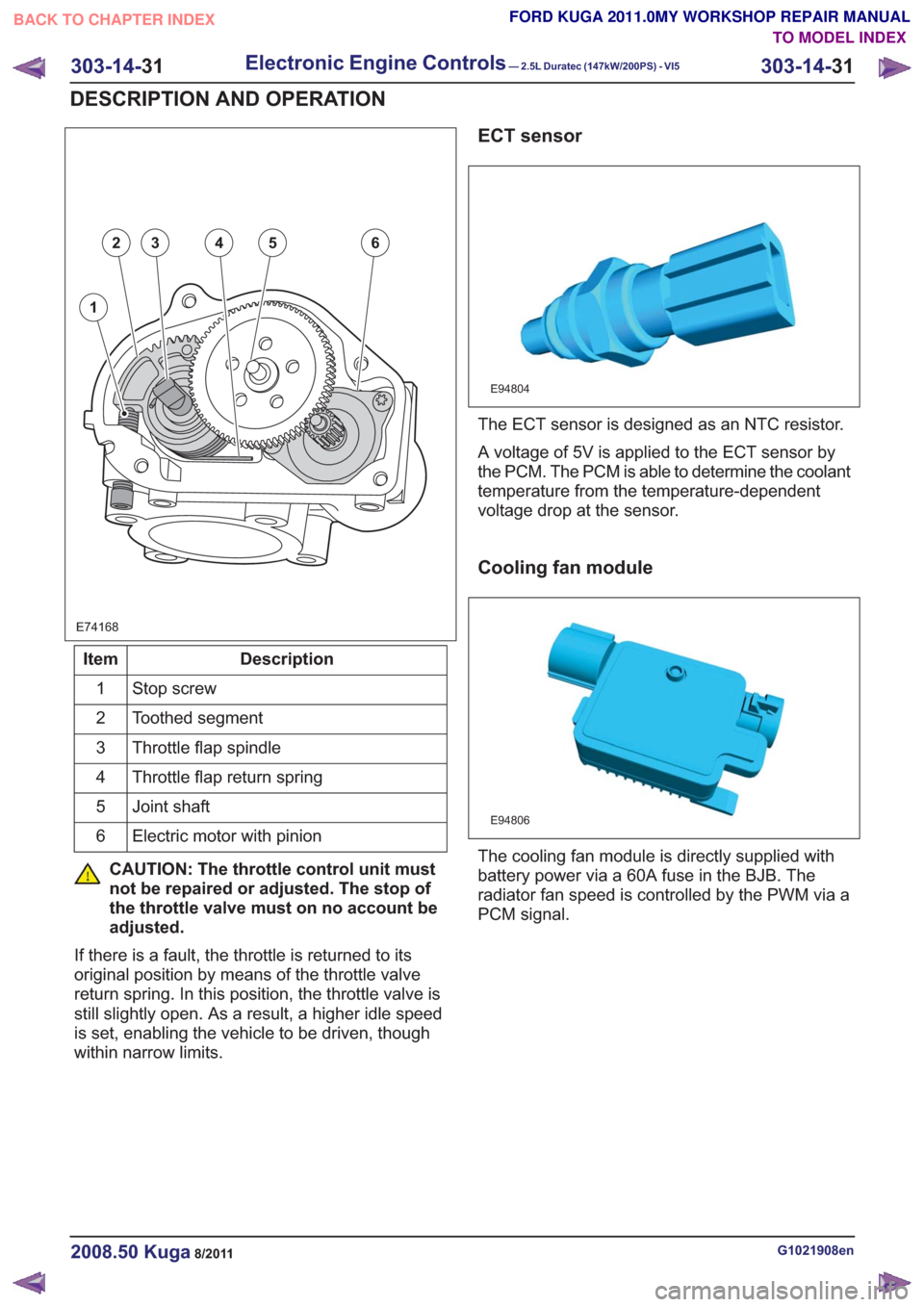
E74168
1
23456
Description
Item
Stop screw
1
Toothed segment
2
Throttle flap spindle
3
Throttle flap return spring
4
Joint shaft
5
Electric motor with pinion
6
CAUTION: The throttle control unit must
not be repaired or adjusted. The stop of
the throttle valve must on no account be
adjusted.
If there is a fault, the throttle is returned to its
original position by means of the throttle valve
return spring. In this position, the throttle valve is
still slightly open. As a result, a higher idle speed
is set, enabling the vehicle to be driven, though
within narrow limits.
ECT sensor
E94804
The ECT sensor is designed as an NTC resistor.
A voltage of 5V is applied to the ECT sensor by
the PCM. The PCM is able to determine the coolant
temperature from the temperature-dependent
voltage drop at the sensor.
Cooling fan module
E94806
The cooling fan module is directly supplied with
battery power via a 60A fuse in the BJB. The
radiator fan speed is controlled by the PWM via a
PCM signal.
G1021908en2008.50 Kuga8/2011
303-14- 31
Electronic Engine Controls— 2.5L Duratec (147kW/200PS) - VI5303-14-
31
DESCRIPTION AND OPERATION
TO MODEL INDEX
BACK TO CHAPTER INDEX
FORD KUGA 2011.0MY WORKSHOP REPAIR MANUAL
Page 1806 of 2057
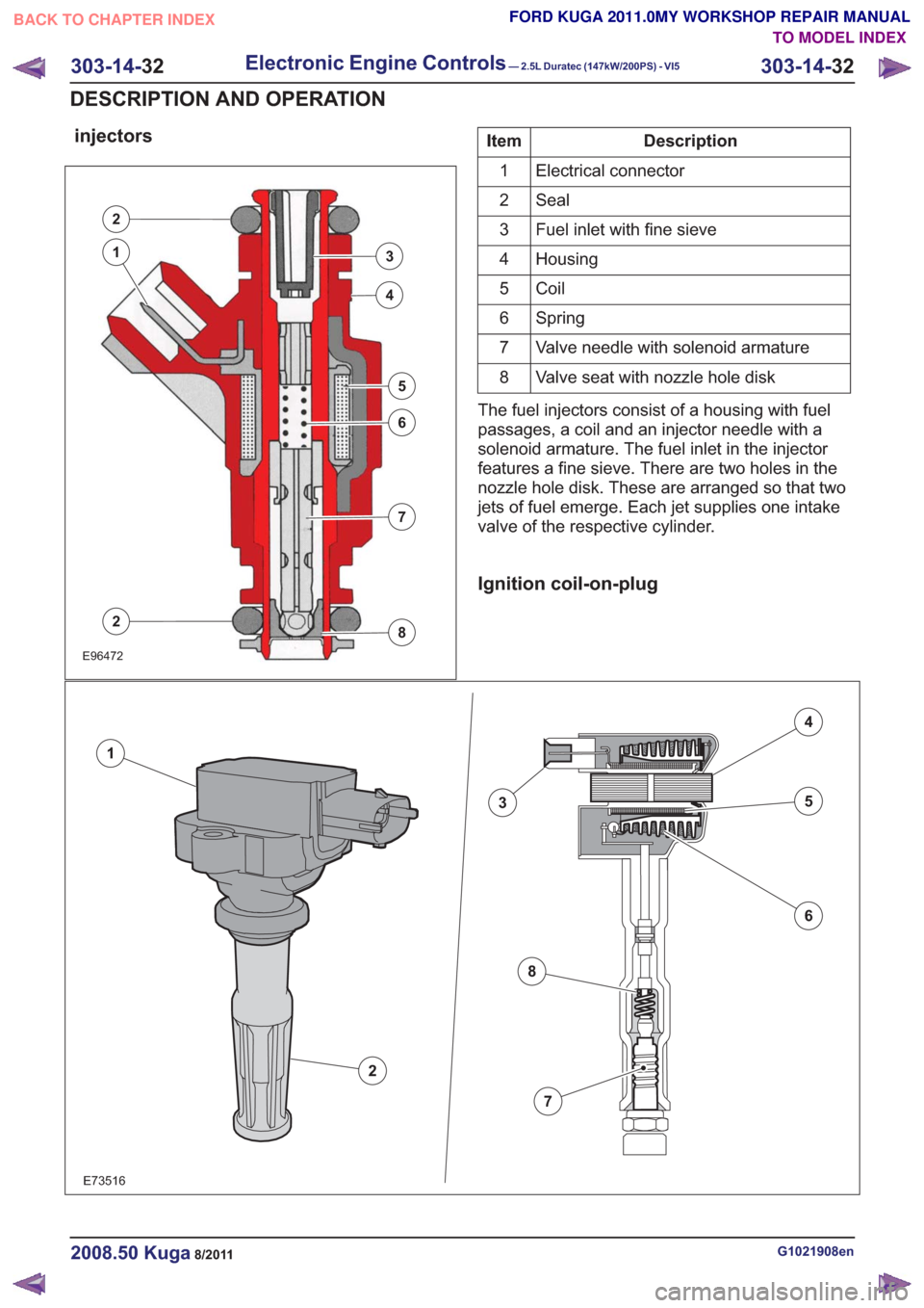
injectors
E96472
2
3
4
5
6
7
8
1
2
Description
Item
Electrical connector
1
Seal
2
Fuel inlet with fine sieve
3
Housing
4
Coil
5
Spring
6
Valve needle with solenoid armature
7
Valve seat with nozzle hole disk
8
The fuel injectors consist of a housing with fuel
passages, a coil and an injector needle with a
solenoid armature. The fuel inlet in the injector
features a fine sieve. There are two holes in the
nozzle hole disk. These are arranged so that two
jets of fuel emerge. Each jet supplies one intake
valve of the respective cylinder.
Ignition coil-on-plug
E73516
2
1
3
4
5
6
7
8
G1021908en2008.50 Kuga8/2011
303-14- 32
Electronic Engine Controls— 2.5L Duratec (147kW/200PS) - VI5303-14-
32
DESCRIPTION AND OPERATION
TO MODEL INDEX
BACK TO CHAPTER INDEX
FORD KUGA 2011.0MY WORKSHOP REPAIR MANUAL
Page 1807 of 2057
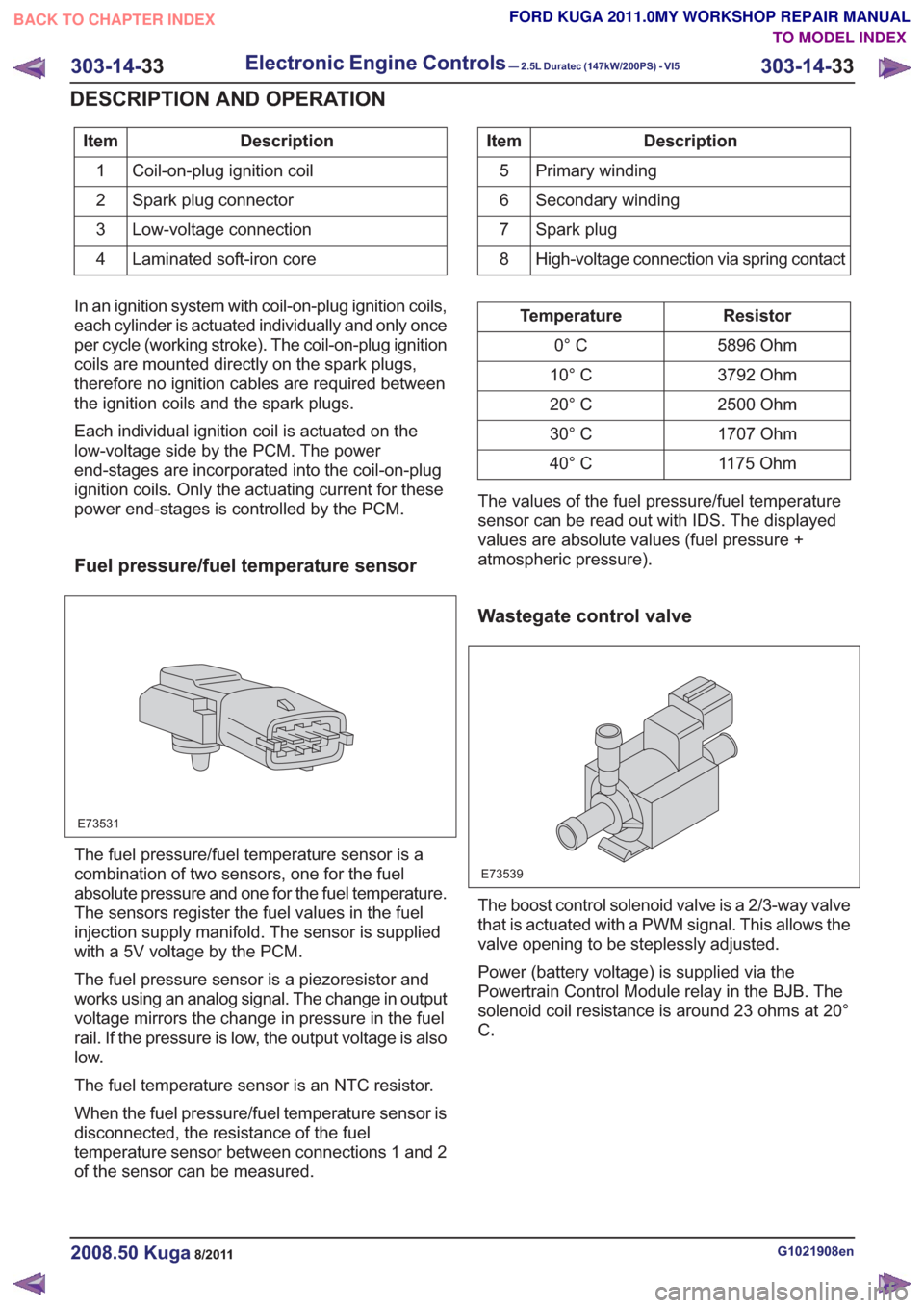
Description
Item
Coil-on-plug ignition coil
1
Spark plug connector
2
Low-voltage connection
3
Laminated soft-iron core
4Description
Item
Primary winding
5
Secondary winding
6
Spark plug
7
High-voltage connection via spring contact
8
In an ignition system with coil-on-plug ignition coils,
each cylinder is actuated individually and only once
per cycle (working stroke). The coil-on-plug ignition
coils are mounted directly on the spark plugs,
therefore no ignition cables are required between
the ignition coils and the spark plugs.
Each individual ignition coil is actuated on the
low-voltage side by the PCM. The power
end-stages are incorporated into the coil-on-plug
ignition coils. Only the actuating current for these
power end-stages is controlled by the PCM.
Fuel pressure/fuel temperature sensor
E73531
The fuel pressure/fuel temperature sensor is a
combination of two sensors, one for the fuel
absolute pressure and one for the fuel temperature.
The sensors register the fuel values in the fuel
injection supply manifold. The sensor is supplied
with a 5V voltage by the PCM.
The fuel pressure sensor is a piezoresistor and
works using an analog signal. The change in output
voltage mirrors the change in pressure in the fuel
rail. If the pressure is low, the output voltage is also
low.
The fuel temperature sensor is an NTC resistor.
When the fuel pressure/fuel temperature sensor is
disconnected, the resistance of the fuel
temperature sensor between connections 1 and 2
of the sensor can be measured.
Resistor
Temperature
5896 Ohm
0° C
3792 Ohm
10° C
2500 Ohm
20° C
1707 Ohm
30° C
1175 Ohm
40° C
The values of the fuel pressure/fuel temperature
sensor can be read out with IDS. The displayed
values are absolute values (fuel pressure +
atmospheric pressure).
Wastegate control valve
E73539
The boost control solenoid valve is a 2/3-way valve
that is actuated with a PWM signal. This allows the
valve opening to be steplessly adjusted.
Power (battery voltage) is supplied via the
Powertrain Control Module relay in the BJB. The
solenoid coil resistance is around 23 ohms at 20°
C.
G1021908en2008.50 Kuga8/2011
303-14- 33
Electronic Engine Controls— 2.5L Duratec (147kW/200PS) - VI5303-14-
33
DESCRIPTION AND OPERATION
TO MODEL INDEX
BACK TO CHAPTER INDEX
FORD KUGA 2011.0MY WORKSHOP REPAIR MANUAL
Page 1969 of 2057
SECTION 310-00 Fuel System - General Information
VEHICLE APPLICATION:2008.50 Kuga
PA G E
CONTENTS
DIAGNOSIS AND TESTING
310-00-2
Fuel System — Vehicles With: Fuel Additive Tank .............................................................
310-00-2
Principles of Operation ........................................................................\
...............................
310-00-2
Inspection and Verification ........................................................................\
..........................
GENERAL PROCEDURES 310-00-3
Spring Lock Couplings ........................................................................\
................................
310-00-3
Disconnect ........................................................................\
..................................................
310-00-5
Connect ........................................................................\
......................................................
310-00-6
Quick Release Coupling ........................................................................\
.............................
310-00-6
Disconnect ........................................................................\
..................................................
310-00-7
Connect ........................................................................\
......................................................
310-00-8
Fuel System Pressure Check — 2.5L Duratec (162kW/220PS) - VI5 ................................
310-00-10
Fuel System Pressure Release ........................................................................\
..................
310-00-10
Release ........................................................................\
......................................................
310-00-11
Fuel Tank Draining ........................................................................\
......................................
310-00-1
Fuel System - General Information
310-00- 1
.
TO MODEL INDEX
BACK TO CHAPTER INDEX
FORD KUGA 2011.0MY WORKSHOP REPAIR MANUAL
Page 1971 of 2057
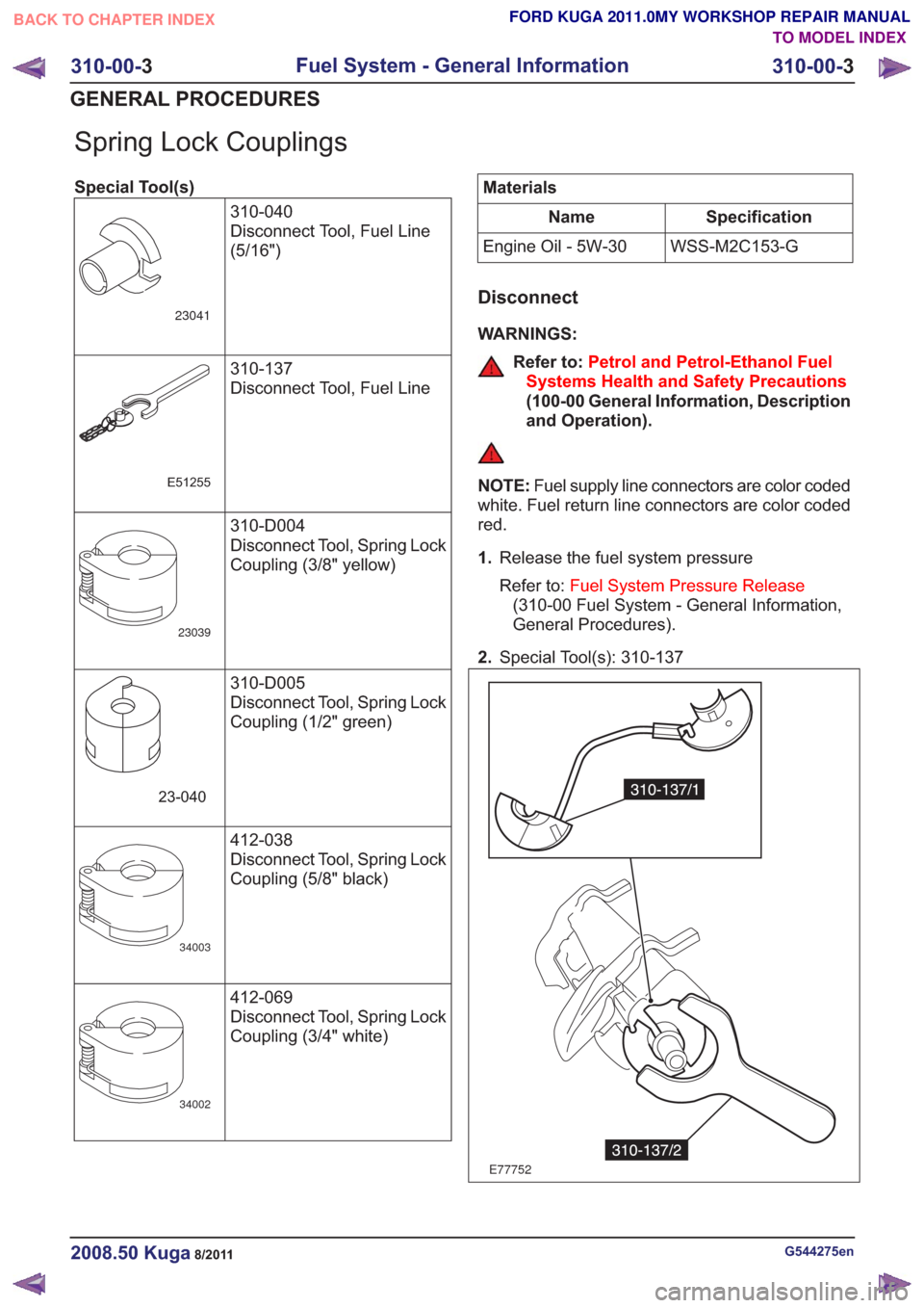
Spring Lock Couplings
Special Tool(s)310-040
Disconnect Tool, Fuel Line
(5/16")
23041
310-137
Disconnect Tool, Fuel Line
E51255
310-D004
Disconnect Tool, Spring Lock
Coupling (3/8" yellow)
23039
310-D005
Disconnect Tool, Spring Lock
Coupling (1/2" green)
23-040
412-038
Disconnect Tool, Spring Lock
Coupling (5/8" black)
34003
412-069
Disconnect Tool, Spring Lock
Coupling (3/4" white)
34002
Materials
Specification
Name
WSS-M2C153-G
Engine Oil - 5W-30
Disconnect
WARNINGS:
Refer to: Petrol and Petrol-Ethanol Fuel
Systems Health and Safety Precautions
(100-00 General Information, Description
and Operation).
NOTE: Fuel supply line connectors are color coded
white. Fuel return line connectors are color coded
red.
1. Release the fuel system pressure
Refer to: Fuel System Pressure Release
(310-00 Fuel System - General Information,
General Procedures).
2. Special Tool(s): 310-137
E77752
G544275en2008.50 Kuga8/2011
310-00- 3
Fuel System - General Information
310-00- 3
GENERAL PROCEDURES
TO MODEL INDEX
BACK TO CHAPTER INDEX
FORD KUGA 2011.0MY WORKSHOP REPAIR MANUAL
Page 1987 of 2057
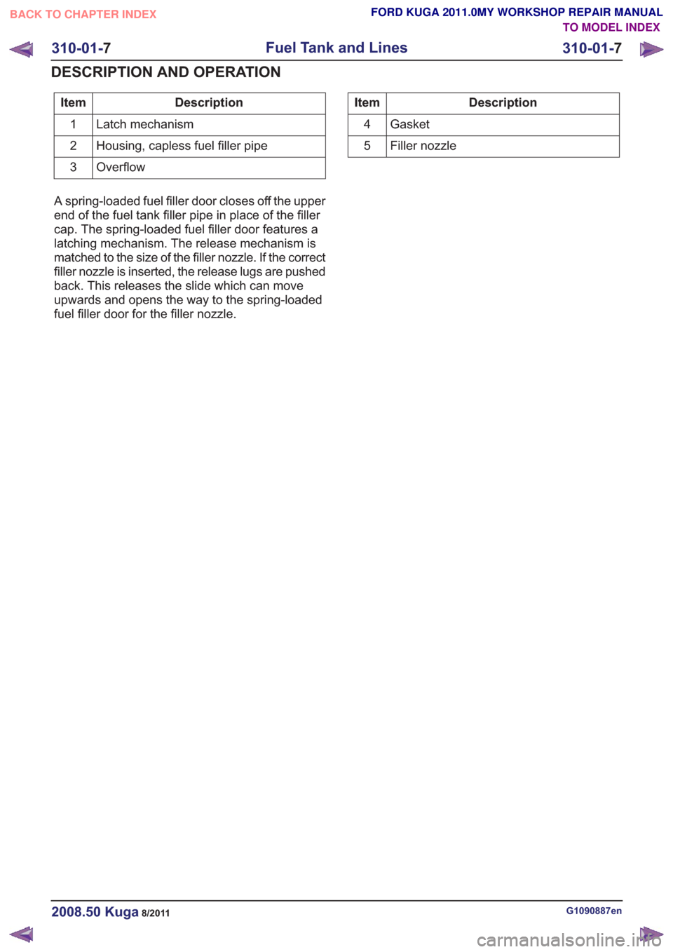
Description
Item
Latch mechanism
1
Housing, capless fuel filler pipe
2
Overflow
3Description
Item
Gasket
4
Filler nozzle
5
A spring-loaded fuel filler door closes off the upper
end of the fuel tank filler pipe in place of the filler
cap. The spring-loaded fuel filler door features a
latching mechanism. The release mechanism is
matched to the size of the filler nozzle. If the correct
filler nozzle is inserted, the release lugs are pushed
back. This releases the slide which can move
upwards and opens the way to the spring-loaded
fuel filler door for the filler nozzle.
G1090887en2008.50 Kuga8/2011
310-01- 7
Fuel Tank and Lines
310-01- 7
DESCRIPTION AND OPERATION
TO MODEL INDEX
BACK TO CHAPTER INDEX
FORD KUGA 2011.0MY WORKSHOP REPAIR MANUAL