spring FORD KUGA 2011 1.G Repair Manual
[x] Cancel search | Manufacturer: FORD, Model Year: 2011, Model line: KUGA, Model: FORD KUGA 2011 1.GPages: 2057
Page 1549 of 2057
Engine – System Operation and Component Description
System Operation
The variable camshaft timing occurs
electro-hydraulically and individually for both
camshafts.
The camshaft adjusters work according to the vane
cell principle and have an adjustment range of 52°
crank angle on the intake side and 47° crank angle
on the exhaust side. On starting the engine and
during idling, both camshafts are mechanically
locked in their starting positions. The exhaust
camshaft is in the early position and the intake
camshaft is in the late position. The camshaftadjuster on the exhaust side has a torsion spring
which compensates the camshaft drive torque.
This ensures that the assembly can return to the
starting position under all operating conditions and
when the engine is turned off.
Internal exhaust gas recirculation can be realized
through continuous adjustment of the timings. This
results in better fuel consumption and more
favorable combustion temperatures which produce
less pollutants. This means that pollutant level IV
can be adhered to with a 3-way catalytic converter.
The variable timings also make it possible to
optimize performance with wide open throttle.
G1032416en2008.50 Kuga8/2011
303-01-
16
Engine— 2.5L Duratec (147kW/200PS) - VI5303-01-
16
DESCRIPTION AND OPERATION
TO MODEL INDEX
BACK TO CHAPTER INDEX
FORD KUGA 2011.0MY WORKSHOP REPAIR MANUAL
Page 1550 of 2057
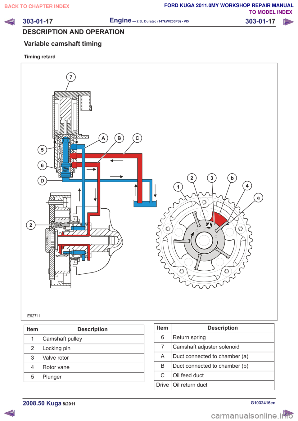
Variable camshaft timing
Timing retard
E62711
Description
Item
Camshaft pulley
1
Locking pin
2
Valve rotor
3
Rotor vane
4
Plunger
5Description
Item
Return spring
6
Camshaft adjuster solenoid
7
Duct connected to chamber (a)
A
Duct connected to chamber (b)
B
Oil feed duct
C
Oil return duct
Drive
G1032416en2008.50 Kuga8/2011
303-01- 17
Engine— 2.5L Duratec (147kW/200PS) - VI5303-01-
17
DESCRIPTION AND OPERATION
TO MODEL INDEX
BACK TO CHAPTER INDEX
FORD KUGA 2011.0MY WORKSHOP REPAIR MANUAL
Page 1556 of 2057
Valve Stem Seals(21 238 0)
Special Tool(s)303-361B
Compressor, Valve Spring
E62757
303-361B-06
Adapter for 303-361B
E62041
303-363
Adapter, Air Supply (Cylinder
Head)
21157
303-508
Pliers, Valve Stem Seal
21211
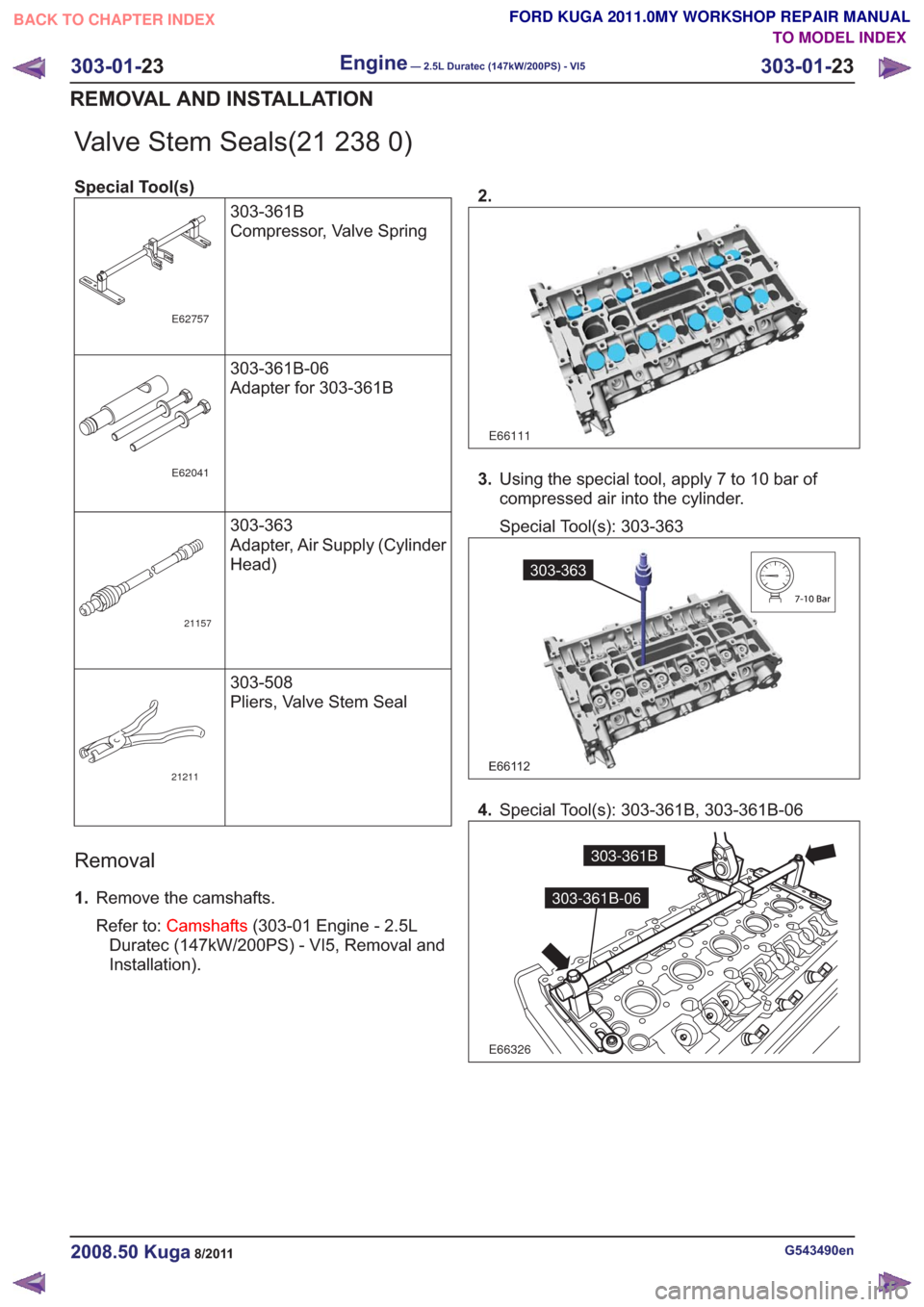
Removal
1.Remove the camshafts.
Refer to: Camshafts (303-01 Engine - 2.5L
Duratec (147kW/200PS) - VI5, Removal and
Installation). 2.
E66111
3.
Using the special tool, apply 7 to 10 bar of
compressed air into the cylinder.
Special Tool(s): 303-363
E66112
303-363
4.Special Tool(s): 303-361B, 303-361B-06
E66326
303-361B
303-361B-06
G543490en2008.50 Kuga8/2011
303-01- 23
Engine— 2.5L Duratec (147kW/200PS) - VI5303-01-
23
REMOVAL AND INSTALLATION
TO MODEL INDEX
BACK TO CHAPTER INDEX
FORD KUGA 2011.0MY WORKSHOP REPAIR MANUAL
Page 1560 of 2057
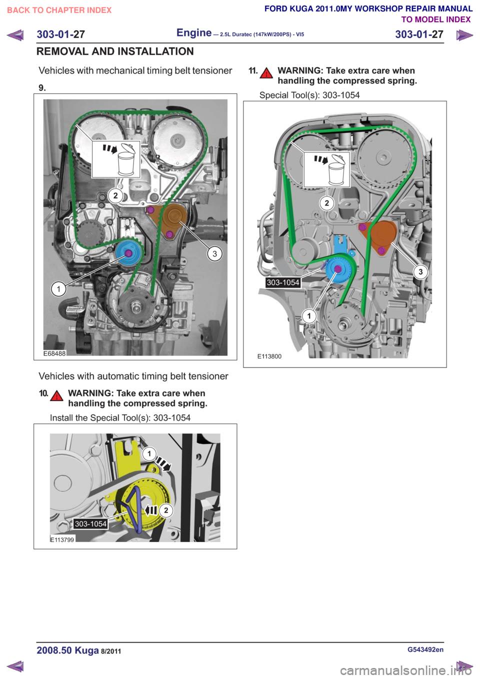
Vehicles with mechanical timing belt tensioner
9.
E68488
1
3
2
Vehicles with automatic timing belt tensioner
10. WARNING: Take extra care whenhandling the compressed spring.
Install the Special Tool(s): 303-1054
1
2
E113799
303-1054
11. WARNING: Take extra care whenhandling the compressed spring.
Special Tool(s): 303-1054
E113800
1
2
3
303-1054
G543492en2008.50 Kuga8/2011
303-01- 27
Engine— 2.5L Duratec (147kW/200PS) - VI5303-01-
27
REMOVAL AND INSTALLATION
TO MODEL INDEX
BACK TO CHAPTER INDEX
FORD KUGA 2011.0MY WORKSHOP REPAIR MANUAL
Page 1561 of 2057
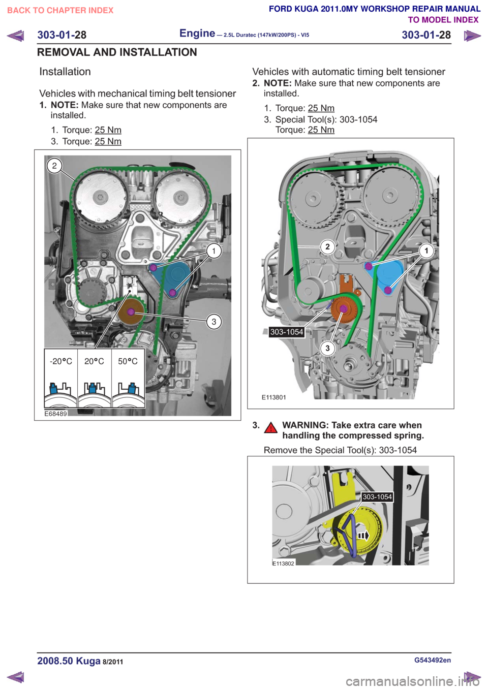
Installation
Vehicles with mechanical timing belt tensioner
1. NOTE:Make sure that new components are
installed.
1. Torque: 25
Nm
3. Torque: 25Nm
E68489
3
1
2
-20 C 20 C 50 C
Vehicles with automatic timing belt tensioner
2. NOTE: Make sure that new components are
installed.
1. Torque: 25
Nm
3. Special Tool(s): 303-1054 Torque: 25
Nm
E113801
12
3
303-1054
3. WARNING: Take extra care when handling the compressed spring.
Remove the Special Tool(s): 303-1054
E113802
303-1054
G543492en2008.50 Kuga8/2011
303-01- 28
Engine— 2.5L Duratec (147kW/200PS) - VI5303-01-
28
REMOVAL AND INSTALLATION
TO MODEL INDEX
BACK TO CHAPTER INDEX
FORD KUGA 2011.0MY WORKSHOP REPAIR MANUAL
Page 1573 of 2057

Vehicles with automatic timing belt tensioner
7. NOTE:Make sure that new components are
installed.
1. Torque: 25
Nm
3. Special Tool(s): 303-1054 Torque: 25
Nm
E113801
12
3
303-1054
8. WARNING: Take extra care when handling the compressed spring.
Remove the Special Tool(s): 303-1054
E113802
303-1054
All vehicles
9.Torque: 120Nm
E68746
10.Remove the Special Tool(s): 303-1178
E66324
303-1178
11 .Remove the Special Tool(s): 303-1182
E66328
303-1182
G1166799en2008.50 Kuga8/2011
303-01- 40
Engine— 2.5L Duratec (147kW/200PS) - VI5303-01-
40
REMOVAL AND INSTALLATION
TO MODEL INDEX
BACK TO CHAPTER INDEX
FORD KUGA 2011.0MY WORKSHOP REPAIR MANUAL
Page 1618 of 2057
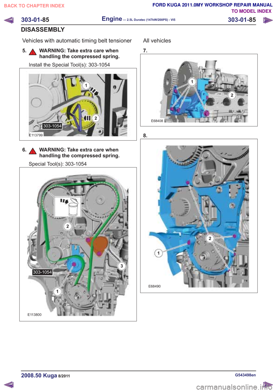
Vehicles with automatic timing belt tensioner
5. WARNING: Take extra care whenhandling the compressed spring.
6. WARNING: Take extra care whenhandling the compressed spring.
All vehicles
7.
G543498en2008.50 Kuga8/2011
303-01- 85
Engine— 2.5L Duratec (147kW/200PS) - VI5303-01-
85
DISASSEMBLY
TO MODEL INDEX
BACK TO CHAPTER INDEX
FORD KUGA 2011.0MY WORKSHOP REPAIR MANUAL
Install the Special Tool(s): 303-1054
1
2
E113799
303-1054
Special Tool(s): 303-1054
E113800
1
2
3
303-1054
E68408
1
2
8.
E68490
1
2
Page 1626 of 2057
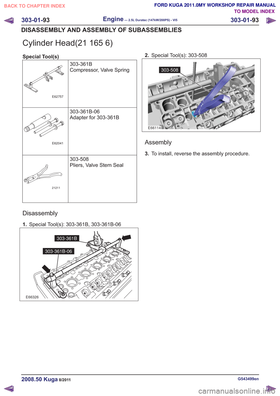
Cylinder Head(21 165 6)
Special Tool(s)303-361B
Compressor, Valve Spring
E62757
303-361B-06
Adapter for 303-361B
E62041
303-508
Pliers, Valve Stem Seal
21211
Disassembly
1.Special Tool(s): 303-361B, 303-361B-06
E66326
303-361B
303-361B-06
2.Special Tool(s): 303-508
E66114
303-508
Assembly
3.To install, reverse the assembly procedure.
G543499en2008.50 Kuga8/2011
303-01- 93
Engine— 2.5L Duratec (147kW/200PS) - VI5303-01-
93
DISASSEMBLY AND ASSEMBLY OF SUBASSEMBLIES
TO MODEL INDEX
BACK TO CHAPTER INDEX
FORD KUGA 2011.0MY WORKSHOP REPAIR MANUAL
Page 1641 of 2057
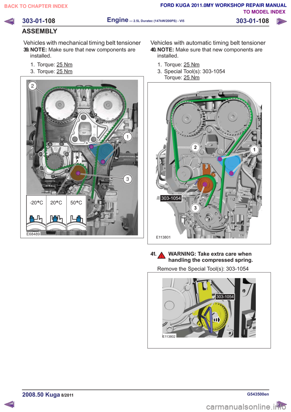
Vehicles with mechanical timing belt tensioner
39. N O T E :Make sure that new components are
installed.
1. Torque: 25
Nm
3. Torque: 25Nm
E68489
3
1
2
-20 C 20 C 50 C
Vehicles with automatic timing belt tensioner
40. N O T E : Make sure that new components are
installed.
1. Torque: 25
Nm
3. Special Tool(s): 303-1054 Torque: 25
Nm
E113801
12
3
303-1054
41. WARNING: Take extra care when handling the compressed spring.
Remove the Special Tool(s): 303-1054
E113802
303-1054
G543500en2008.50 Kuga8/2011
303-01- 108
Engine— 2.5L Duratec (147kW/200PS) - VI5303-01-
108
ASSEMBLY
TO MODEL INDEX
BACK TO CHAPTER INDEX
FORD KUGA 2011.0MY WORKSHOP REPAIR MANUAL
Page 1720 of 2057
Turbocharger – Overview
Turbocharger(s)
CAUTION: Do not switch off the engine
while it is running at high speed. If the
engine is switched off while it is running
at high speed, the turbocharger will
continue to run after the engine oil
pressure has already dropped to zero. This
will cause premature wear in the
turbocharger bearings.
A TC consists of an exhaust turbine located in the
exhaust gas flow, this turbine is connected to a
compressor by a shaft. The turbine is made to
rotate by the exhaust gas flow from the engine and
thus drives the compressor. The compressor
increases the pressure in the engine intake tract
so that a greater mass of air enters the cylinder
during the intake stroke.
The turbine housing of the TC is integrated into the
exhaust manifold. This construction offers
thermodynamic advantages compared with the
usual construction, the maximum exhaust
temperature is up to 1050°C.
The maximum boost pressure is 0.65 bar.
The exhaust manifold is secured to the exhaust
side of the cylinder head with 12 self-locking nuts.
The exhaust manifold gasket is a multi-layer steel
gasket and cannot be reused. In order to
compensate for the thermal expansion of the
exhaust manifold, the flange of the TC is provided
with two grooves.
The TC and the exhaust manifold are joined by a
hose clip. The hose clip must not be loosened or
removed. The TC and the exhaust manifold are
not available as separate replacement parts,
exchange is only possible as a complete unit.
The turbocharger heat shield is secured to the
exhaust manifold by four bolts. Two of the bolts
have spring washers underneath their heads.
During removal, make a note of the installation
location of the spring washers to refer to during
installation.
The recirculated air valve is built into the TC
housing and cannot be changed.
The Ford diagnostic unit can test the operation of
the wastegate control valve using actuator
diagnosis.
The boost pressure regulator is set in the factory.
Adjustments to the boost pressure regulator must never be attempted. A red colored seal is applied
to the adjustment nut of the operating rod, in order
to monitor the factory setting of the boost pressure.
The bearings of the TC are lubricated with engine
oil. The engine oil passes from the cylinder block
through the oil supply pipe to the TC. The oil is
returned to the oil pan through the oil return pipe,
The TC is cooled by the engine coolant circuit.
When installing hoses and lines, make certain that
their ends are free of oil residues and dirt.
G1032425en2008.50 Kuga8/2011
303-04B-
4
Fuel Charging and Controls - Turbocharger
—
2.5L Duratec (147kW/200PS) - VI5
303-04B- 4
DESCRIPTION AND OPERATION
TO MODEL INDEX
BACK TO CHAPTER INDEX
FORD KUGA 2011.0MY WORKSHOP REPAIR MANUAL