engine remove FORD KUGA 2011 1.G Manual Online
[x] Cancel search | Manufacturer: FORD, Model Year: 2011, Model line: KUGA, Model: FORD KUGA 2011 1.GPages: 2057
Page 1839 of 2057
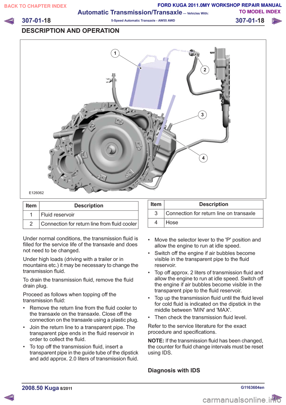
E126062
2
1
3
4
Description
Item
Fluid reservoir
1
Connection for return line from fluid cooler
2Description
Item
Connection for return line on transaxle
3
Hose
4
Under normal conditions, the transmission fluid is
filled for the service life of the transaxle and does
not need to be changed.
Under high loads (driving with a trailer or in
mountains etc.) it may be necessary to change the
transmission fluid.
To drain the transmission fluid, remove the fluid
drain plug.
Proceed as follows when topping off the
transmission fluid:
• Remove the return line from the fluid cooler to the transaxle on the transaxle. Close off the
connection on the transaxle using a plastic plug.
• Join the return line to a transparent pipe. The transparent pipe ends in the fluid reservoir in
order to collect the fluid.
• To top off the transmission fluid, insert a transparent pipe in the guide tube of the dipstick
and add approx. 2.0 liters of transmission fluid. • Move the selector lever to the 'P' position and
allow the engine to run at idle speed.
• Switch off the engine if air bubbles become visible in the transparent pipe to the fluid
reservoir.
• Top off approx. 2 liters of transmission fluid and allow the engine to run at idle speed. Switch off
the engine if air bubbles become visible in the
transparent pipe to the fluid reservoir.
• Top up the transmission fluid until the fluid level for cold fluid is indicated on the dipstick in the
middle between 'MIN' and 'MAX'.
• Then check the transmission fluid level.
Refer to the service literature for the exact
procedure and specifications.
NOTE: If the transmission fluid has been changed,
the counter for fluid change intervals must be reset
using IDS.
Diagnosis with IDS
G1163604en2008.50 Kuga8/2011
307-01- 18
Automatic Transmission/Transaxle
— Vehicles With:
5-Speed Automatic Transaxle - AW55 AWD
307-01- 18
DESCRIPTION AND OPERATION
TO MODEL INDEX
BACK TO CHAPTER INDEX
FORD KUGA 2011.0MY WORKSHOP REPAIR MANUAL
Page 1978 of 2057
Fuel System Pressure Release
Release
1.Refer to: Petrol and Petrol-Ethanol Fuel
Systems Health and Safety Precautions
(100-00 General Information, Description and
Operation).
2. Remove the fuel pump and sender unit fuse.
3. Start the engine and allow it to idle until the
engine stalls.
4. Crank the engine for approximately five seconds
to make sure that the fuel rail pressure is
released.
5. Install the fuel pump and sender unit fuse.
G551380en2008.50 Kuga8/2011
310-00- 10
Fuel System - General Information
310-00- 10
GENERAL PROCEDURES
TO MODEL INDEX
BACK TO CHAPTER INDEX
FORD KUGA 2011.0MY WORKSHOP REPAIR MANUAL
Page 1979 of 2057
Fuel Tank Draining
General EquipmentFluid Container
Fuel Tank Draining Equipment
Hose Clamp Remover/Installer
Activation
CAUTION: If the fuel tank has been filled
with the wrong type of fuel, the engine
must not be started.
NOTE: Removal steps in this procedure may
contain installation details.
6. Refer to: Petrol and Petrol-Ethanol Fuel
Systems Health and Safety Precautions
(100-00 General Information, Description and
Operation).
7. Refer to: Lifting(100-02 Jacking and Lifting,
Description and Operation).
8. WARNINGS:
Fuel may still be present in the fuel tank
after draining.
Be prepared to collect escaping fluids.
CAUTION: Use suitable paper to absorb
any escaping fluid. NOTE:
Make sure that a new component is
installed.
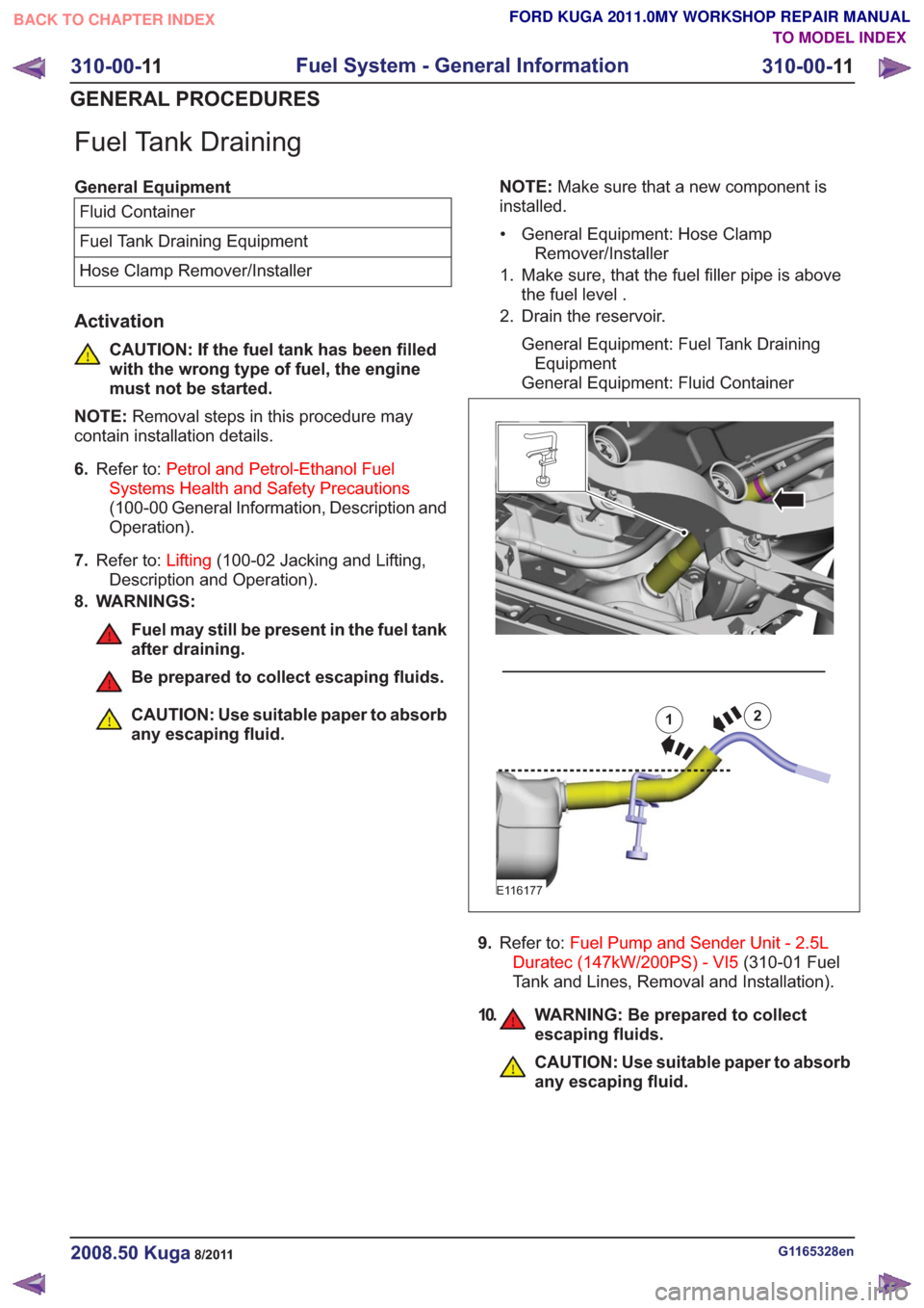
• General Equipment: Hose Clamp Remover/Installer
1. Make sure, that the fuel filler pipe is above the fuel level .
2. Drain the reservoir.
General Equipment: Fuel Tank DrainingEquipment
General Equipment: Fluid Container12
E116177
9. Refer to: Fuel Pump and Sender Unit - 2.5L
Duratec (147kW/200PS) - VI5 (310-01 Fuel
Tank and Lines, Removal and Installation).
10. WARNING: Be prepared to collect escaping fluids.
CAUTION: Use suitable paper to absorb
any escaping fluid.
G1165328en2008.50 Kuga8/2011
310-00- 11
Fuel System - General Information
310-00- 11
GENERAL PROCEDURES
TO MODEL INDEX
BACK TO CHAPTER INDEX
FORD KUGA 2011.0MY WORKSHOP REPAIR MANUAL
Page 1986 of 2057
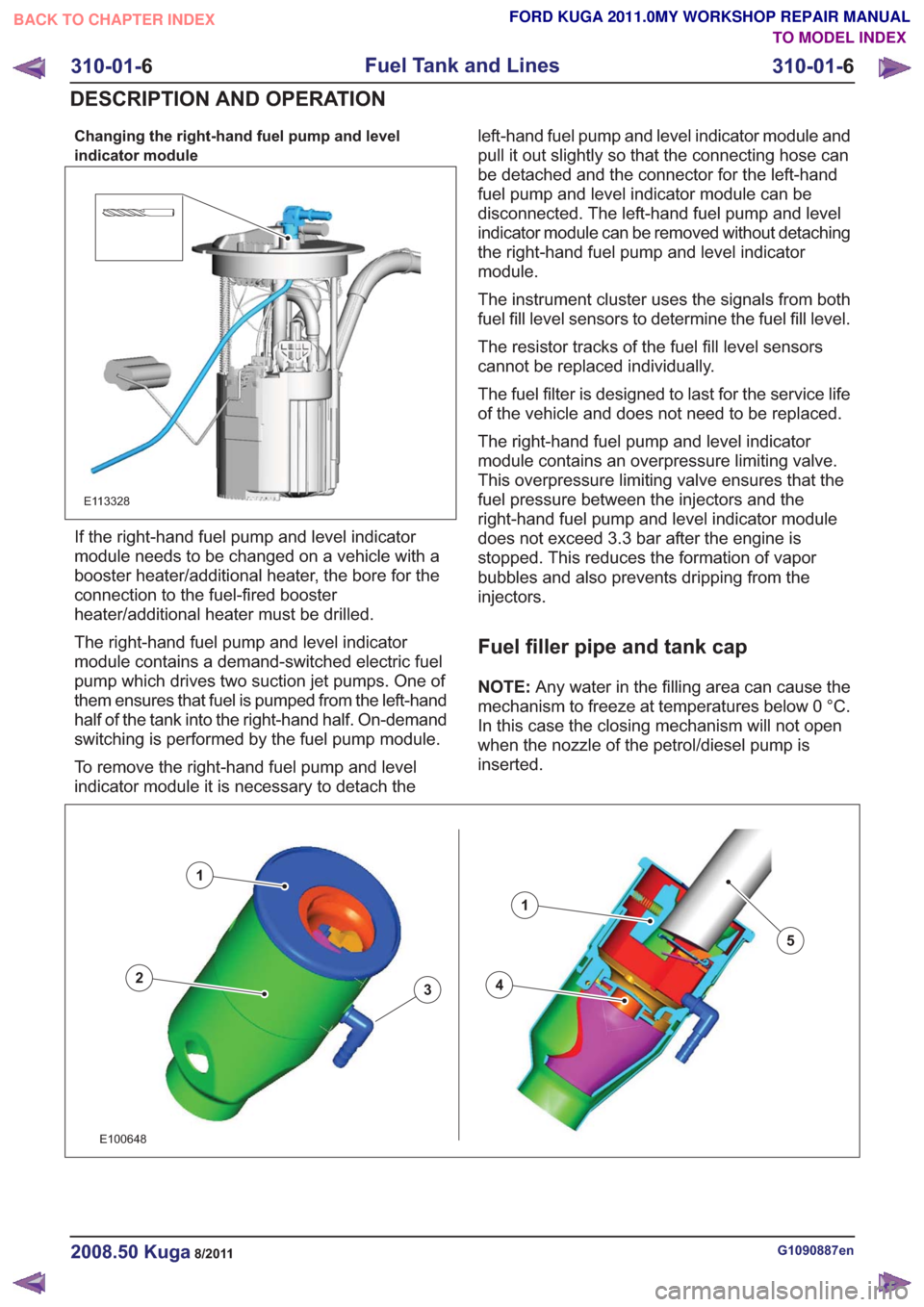
Changing the right-hand fuel pump and level
indicator module
E113328
If the right-hand fuel pump and level indicator
module needs to be changed on a vehicle with a
booster heater/additional heater, the bore for the
connection to the fuel-fired booster
heater/additional heater must be drilled.
The right-hand fuel pump and level indicator
module contains a demand-switched electric fuel
pump which drives two suction jet pumps. One of
them ensures that fuel is pumped from the left-hand
half of the tank into the right-hand half. On-demand
switching is performed by the fuel pump module.
To remove the right-hand fuel pump and level
indicator module it is necessary to detach theleft-hand fuel pump and level indicator module and
pull it out slightly so that the connecting hose can
be detached and the connector for the left-hand
fuel pump and level indicator module can be
disconnected. The left-hand fuel pump and level
indicator module can be removed without detaching
the right-hand fuel pump and level indicator
module.
The instrument cluster uses the signals from both
fuel fill level sensors to determine the fuel fill level.
The resistor tracks of the fuel fill level sensors
cannot be replaced individually.
The fuel filter is designed to last for the service life
of the vehicle and does not need to be replaced.
The right-hand fuel pump and level indicator
module contains an overpressure limiting valve.
This overpressure limiting valve ensures that the
fuel pressure between the injectors and the
right-hand fuel pump and level indicator module
does not exceed 3.3 bar after the engine is
stopped. This reduces the formation of vapor
bubbles and also prevents dripping from the
injectors.
Fuel filler pipe and tank cap
NOTE:
Any water in the filling area can cause the
mechanism to freeze at temperatures below 0 °C.
In this case the closing mechanism will not open
when the nozzle of the petrol/diesel pump is
inserted.
43
1
2
1
5
43
1
2
1
5
E100648
G1090887en2008.50 Kuga8/2011
310-01- 6
Fuel Tank and Lines
310-01- 6
DESCRIPTION AND OPERATION
TO MODEL INDEX
BACK TO CHAPTER INDEX
FORD KUGA 2011.0MY WORKSHOP REPAIR MANUAL
Page 2015 of 2057
• The refrigerant line between the fixed orificetube and the evaporator must be cold from the
point where the fixed orifice tube is installed.
Depending on the weather, the refrigerant line
may also have ice on its surface.
• The refrigerant line between the evaporator and the A/C compressor including the dehydrator
must be cold.
Evaporator outlet line temperature test
To test the power of the A/C system, the
temperature at the evaporator outlet line must be
measured. To do this, the following preconditions
must be met:
• Open all windows.
• Set the air distribution to the defrost/dashboardposition and open all the ventilation nozzles.
• DO NOT switch on recirculated air.
• Select lowest blower switch setting.
• Select lowest temperature setting.
NOTE: The temperature measurement cannot be
done with a thermometer which makes no contact.
The surface reflection from the metal line may
cause incorrect readings.
Connect the temperature sensor (Fluke 80 PK-8)
to the outlet line of the evaporator. Locate the
temperature sensor as close as possible to the
evaporator. Connect the temperature sensor to the
multimeter.
Start the engine and allow it to run at idle speed
for several minutes.
Switch on the A/C.
After three minutes, measure the surface
temperature of the evaporator outlet line.
If the temperature measured is 4° C or lower, the
A/C system is OK. If the temperature is higher, the
A/C system may be under-filled. For further
information, refer to
REFER to: Air Conditioning (A/C) System
Recovery, Evacuation and Charging (412-00
Climate Control System - General Information,
General Procedures).
Frequent faults and their causes
If the cooling power of the A/C system is not
adequate, make certain that the temperature
control flap(s) is/are operating correctly. • No or poor cooling performance:
– Blockage or narrowing of a refrigerant line orin the dehydrator. The location of the
blockage or narrowing can easily be located
by temperature comparisons at the
refrigerant lines and the dehydrator. The
blockage or restriction is located at the point
where the temperature difference is
identified. Note: A temperature difference
in the area of the fixed orifice tube is
normal. If the location of the blockage or
narrowing is found, check the corresponding
component and renew as applicable.
• Sudden drop in cooling performance (after the air conditioning has been switched off for
approx. 5 minutes, the cooling performance
returns to normal):
– The cause is an iced-up fixed orifice tubebecause of moisture in the refrigerant circuit.
In order to ensure that moisture is completely
removed from the refrigerant circuit, the
dehydrator should be renewed and the
evacuation time should be extended to 2-3
hours. For further information
REFER to: Air Conditioning (A/C) System
Recovery, Evacuation and Charging
(412-00 Climate Control System - General
Information, General Procedures).
Sequence of A/C Request Signal
NOTE: The electronic automatic temperature
control (EATC) module is integrated into the air
conditioning control assembly.
NOTE: The generic electronic module (GEM) is
an integral part of the central junction box (CJB).
After actuating the A/C ON/OFF switch integrated
into the A/C control assembly, an A/C request
signal is sent from the A/C control assembly
(vehicles with EATC: EATC module) to the GEM.
From there, the signal is sent to the instrument
cluster via the MS-CAN bus. A gateway is installed
in the instrument cluster, which establishes the
connection between the MS-CAN bus and the
HS-CAN bus.
After the signal has been converted in the gateway,
it is relayed to the powertrain control module (PCM)
via the HS-CAN bus. Once all the required
parameters have been met, the PCM switches on
the refrigerant compressor and thus the A/C system
via the A/C clutch relay.
G1055878en2008.50 Kuga8/2011
412-00- 4
Climate Control System - General Information
412-00- 4
DIAGNOSIS AND TESTING
TO MODEL INDEX
BACK TO CHAPTER INDEX
FORD KUGA 2011.0MY WORKSHOP REPAIR MANUAL