sensors FORD KUGA 2011 1.G Workshop Manual
[x] Cancel search | Manufacturer: FORD, Model Year: 2011, Model line: KUGA, Model: FORD KUGA 2011 1.GPages: 2057
Page 187 of 2057

Description
Item
Instrument Cluster
1
PCM (powertrain control module)
2
EHPS (electro-hydraulic power steering)
control module
3
Audio unit
4
GEM (generic electronic module)
5
RCM (restraints control module)
6
PATS transceiver
7 Description
Item
Steering wheel lock module
8
Left-hand steering column switch
9
Fuel level sensor
10
Washer water level warning lamp switch
11
Accelerator pedal position sensor
12
CPP (clutch pedal position) sensor/BPP
(brake pedal position) sensor
13
Lighting control switch
14
System Operation
Instrument Cluster
The instrument cluster contains analog displays
as well as warning and control lamps for displaying
the system status; in addiiton, there is an LCD
indicator field for driver information.
The instrument cluster receives the following
signals from the PCM via the high speed CAN
(controller area network) Bus (HS-CAN):
• Vehicle speed – The PCM receives the necessary signalsfrom the ABS (anti-lock brake system) wheel
sensors from the ABS control unit on the
HS-CAN.
• Engine Coolant Temperature
• Engine oil pressure.
• Engine speed
The instrument cluster receives the following
signals from the GEM via the medium speed CAN
Bus (MS-CAN):
• Ambient temperature
• Brake fluid level
• Handbrake control
• Door latch control
• Liftgate latch control
• High beam control
• Headlamp flasher control
• Direction indicator control
The fuel level signal is sent by the two fuel level
sensors in the fuel pumps in the semitrailer tank,
which is wired to the instrument cluster. The
sensors are connected in series, and the total
resistance is determined from the two individual resistors. The instrument cluster converts the raw
fuel level signal into a damped fuel level value.
The odometer shows the total distance travelled
by the vehicle and is based on the same signal as
is processed for the daily mileage counter. The
value is recorded by the instrument cluster and
stored in a protected EEPROM (Electronically
Erasable Programmable Read Only Memory) area.
This area is a memory protected against
manipulation. If the instrument cluster detects an
error in this memory area, e.g. through damage,
the driver is notified with the "Odometer error"
message.
Message center
The message center is operated using the left-hand
switch on the steering column.
The SET/RESET button is activated to select a
submenu and change the settings. If signal tones
have been activated, a short acoustic signal will
sound each time a button is pressed.
By turning the rotary switch, the different menu
displays can be scrolled through or a setting
selected.
In this display, the navigation system can also
display direction and distance information.
In addition, safety and warning messages can be
displayed in this system, such as "Coolant
overheating", "Engine system error" or "Washer
fluid level too low". In addition to a safety message,
a general warning light (red/yellow) lights up.
G1030770en
2008.50 Kuga 8/2011 413-01-4
Instrument Cluster
413-01-4
DESCRIPTION AND OPERATIONTO MODEL INDEX
BACK TO CHAPTER INDEX
FORD KUGA 2011.0MY WORKSHOP REPAIR MANUAL
Page 200 of 2057
SECTION 413-13 Parking Aid
VEHICLE APPLICATION:
2008.50 Kuga
PAGE
CONTENTS
DESCRIPTION AND OPERATION
413-13-2
Parking Aid (Component Location).....................................................................................
413-13-5
Parking Aid (Overview).......................................................................................................
413-13-5
Parking aid sensors............................................................................................................
413-13-5
Front sensors detection range............................................................................................
413-13-6
Rear sensors detection range............................................................................................
413-13-6
Parking aid camera module................................................................................................
413-13-6
Parking Aid Camera...........................................................................................................
413-13-7
Parking Aid (System Operation and Component Description)...........................................
413-13-7
System Diagram.................................................................................................................
413-13-12
System Operation...............................................................................................................
413-13-12
Parking Aid......................................................................................................................
413-13-13
Parking Aid Camera........................................................................................................
413-13-15
Component Description......................................................................................................413-13-15Rear parking aid speaker................................................................................................
413-13-15Parking aid sensors........................................................................................................
413-13-15Parking aid module.........................................................................................................
413-13-16Front parking aid speaker...............................................................................................
413-13-16Parking aid switch...........................................................................................................
413-13-16Parking aid camera module............................................................................................
413-13-16Parking Aid Camera........................................................................................................
DIAGNOSIS AND TESTING 413-13-17
Parking Aid — Vehicles With: Front Parking Aid................................................................
413-13-17
Principles of Operation.......................................................................................................
413-13-17
Inspection and Verification..................................................................................................
413-13-17
Diagnostic Trouble Codes (DTC) Index..............................................................................
413-13-21
Symptom Chart...................................................................................................................
413-13-21
Pinpoint Tests.....................................................................................................................
413-13-29
Parking Aid — Vehicles With: Rear Parking Aid.................................................................
413-13-29
Principles of Operation.......................................................................................................
413-13-29
Inspection and Verification..................................................................................................
413-13-29
Diagnostic Trouble Codes (DTC) Index..............................................................................
413-13-32
Symptom Chart...................................................................................................................
413-13-32
Pinpoint Tests.....................................................................................................................
REMOVAL AND INSTALLATION 413-13-44
Parking Aid Module.............................................................................................................
413-13-45
Parking Aid Camera Module...............................................................................................
413-13-46
Parking Aid Camera............................................................................................................
413-13-48
Front Parking Aid Speaker.................................................................................................
413-13-49
Rear Parking Aid Speaker..................................................................................................
413-13-50
Front Parking Aid Sensor....................................................................................................
413-13-56
Rear Parking Aid Sensor.................................................................................................... 413-13-1
Parking Aid
413-13-1
.
TO MODEL INDEX
BACK TO CHAPTER INDEX
FORD KUGA 2011.0MY WORKSHOP REPAIR MANUAL
Page 204 of 2057
Parking Aid – Overview
Parking aid sensors
CAUTIONS:
Always keep sensors free from dirt, ice and
snow. Do not use any sharp objects to
clean the sensors. If a high-pressure cleaner is used to wash
the vehicle, the jet must only be aimed at
the sensors briefly at a distance of at least
20 cm.
The parking aid sensors have a separate
decoupling ring, which must be removed before
painting the sensors, and then refitted.
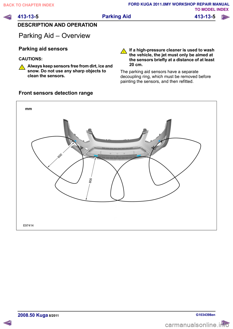
Front sensors detection range G1034398en
2008.50 Kuga 8/2011 413-13-5
Parking Aid
413-13-5
DESCRIPTION AND OPERATIONTO MODEL INDEX
BACK TO CHAPTER INDEX
FORD KUGA 2011.0MY WORKSHOP REPAIR MANUAL600800mmE97414
Page 205 of 2057
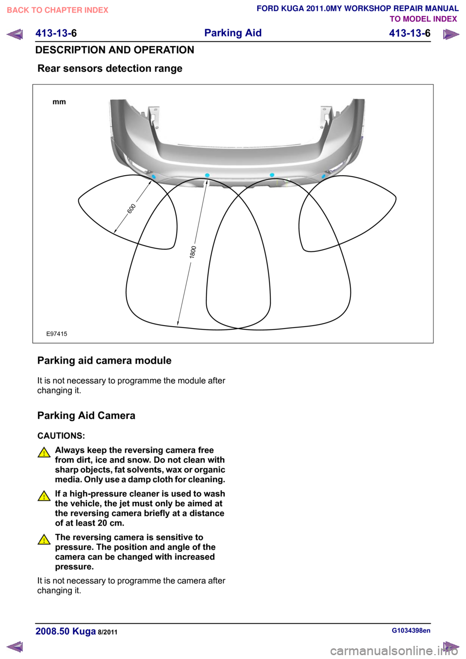
Rear sensors detection range
Parking aid camera module
It is not necessary to programme the module after
changing it.
Parking Aid Camera
CAUTIONS:
Always keep the reversing camera free
from dirt, ice and snow. Do not clean with
sharp objects, fat solvents, wax or organic
media. Only use a damp cloth for cleaning.
If a high-pressure cleaner is used to wash
the vehicle, the jet must only be aimed at
the reversing camera briefly at a distance
of at least 20 cm.
The reversing camera is sensitive to
pressure. The position and angle of the
camera can be changed with increased
pressure.
It is not necessary to programme the camera after
changing it. G1034398en
2008.50 Kuga 8/2011 413-13-6
Parking Aid
413-13-6
DESCRIPTION AND OPERATIONTO MODEL INDEX
BACK TO CHAPTER INDEX
FORD KUGA 2011.0MY WORKSHOP REPAIR MANUAL6001800mmE97415
Page 207 of 2057

Description
Item
Parking aid moduleRefertoComponentDescription:(page
15)
1
Rear parking aid speakerRefertoComponentDescription:(page
15)
2
Generic Electronic Module (GEM)
3
Reverse gear switch
4
Instrument cluster
5
ABS sensor assembly
6
ABS7 Description
Item
Trailer relay
8
Rear parking aid sensorRefer to Component Description: Parking
aidsensors(page15)
9
Rear parking aid sensorRefer to Component Description: Parking
aidsensors(page15)
10
Rear parking aid sensorRefer to Component Description: Parking
aidsensors(page15)
11
Rear parking aid sensorRefer to Component Description: Parking
aidsensors(page15)
12 G1034399en
2008.50 Kuga 8/2011 413-13-8
Parking Aid
413-13-8
DESCRIPTION AND OPERATIONTO MODEL INDEX
BACK TO CHAPTER INDEX
FORD KUGA 2011.0MY WORKSHOP REPAIR MANUAL
Page 211 of 2057

Description
Item
Rear parking aid sensorRefer to Component Description: Parking
aid sensors (page ?)
7
Rear parking aid sensorRefer to Component Description: Parking
aid sensors (page ?)
8 Description
Item
Rear parking aid sensorRefer to Component Description: Parking
aid sensors (page ?)
9
steering angle sensor
10
Navigation device
11
System Operation
Parking Aid WARNING: It is the driver's responsibility
to stay alert during reversing procedures.
The system may fail to detect small
children or animals.
CAUTION: The driver is responsible for
detecting obstacles and judging the
distance between these and the vehicle.
The system may fail to detect some
hanging objects, barriers, narrow obstacles
or painted surfaces, which could damage
the vehicle. Always pay attention when
parking.
The parking aid provides an audible warning to the
driver if there are any obstacles in front of or behind
the vehicle during reverse parking maneuvers.
At low speeds, the parking aid module uses the
parking aid sensors to monitor the area around the
vehicle. If an object is detected within a monitored
area, the parking aid module emits a warning tone
using the respective parking aid speaker.
The rear parking aid is switched on with the
ignition. However, it is only enabled when reverse
gear is selected.
The front and rear parking aid is always switched
off when the ignition is switched on. It is switched
on when reverse gear is selected or if the parking
aid switch in the center console is actuated up to
a speed of 16 km/h.
The parking aid is switched off when the vehicle is
travelling forwards at more than 16 km/h or if the
parking aid switch in the center console is actuated
again.
When the parking aid module activates the system,
the parking aid switch LED is illuminated. If the
vehicle is only fitted with the rear parking aid, there
is no switch.
The parking aid sensors emit a series of ultrasonic
impulses and switch to receiver mode to receive the echo reflected by an obstacle within the
detection range. The received echo signals are
amplified and converted from an analog signal to
a digital signal by the sensor. The digital signal is
passed to the parking aid module and compared
with pre-programmed data stored in an EEPROM
within the module. The module calculates the
distance to the obstacle by measuring the time
taken between the emitted and received impulses.
If no objects are detected there are no further
warning tones. If an object is detected, repeated
audible tones are emitted from either parking aid
speaker(s) as appropriate. The time delay between
the tones decreases as the distance between the
object and the vehicle decreases, until at
approximately 250 mm (10 inches), the audible
tone becomes continuous.
If the distance between the obstacle and the
vehicle does not decrease, the warning tone
remains constant if the object has been detected
by an internal parking aid sensor. If the obstacle
was detected by an external sensor and the
distance remains unchanged, the warning tone
stops after 3 seconds.
The parking aid module continues to monitor the
distance and will resume the warning tones if a
decrease in distance is detected.
If a trailer is connected to the vehicle, a signal is
sent to the GEM (generic electronic module) via
the trailer relay. This signal is sent to the parking
aid module via the MS CAN bus. When the parking
aid module detects that a trailer is connected to
the vehicle, the rear parking aid sensors are
disabled to prevent constant warnings due to the
close proximity of the trailer.
G1034399en
2008.50 Kuga 8/2011 413-13-12
Parking Aid
413-13-12
DESCRIPTION AND OPERATIONTO MODEL INDEX
BACK TO CHAPTER INDEX
FORD KUGA 2011.0MY WORKSHOP REPAIR MANUAL
Page 214 of 2057
Component Description
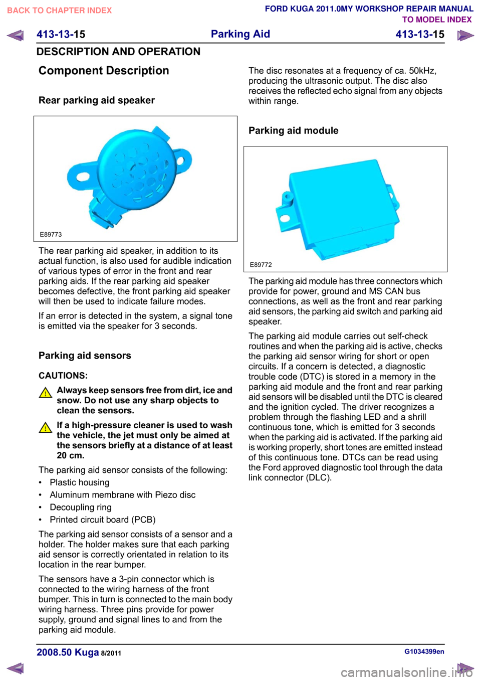
Rear parking aid speaker
The rear parking aid speaker, in addition to its
actual function, is also used for audible indication
of various types of error in the front and rear
parking aids. If the rear parking aid speaker
becomes defective, the front parking aid speaker
will then be used to indicate failure modes.
If an error is detected in the system, a signal tone
is emitted via the speaker for 3 seconds.
Parking aid sensors
CAUTIONS:
Always keep sensors free from dirt, ice and
snow. Do not use any sharp objects to
clean the sensors.
If a high-pressure cleaner is used to wash
the vehicle, the jet must only be aimed at
the sensors briefly at a distance of at least
20 cm.
The parking aid sensor consists of the following:
• Plastic housing
• Aluminum membrane with Piezo disc
• Decoupling ring
• Printed circuit board (PCB)
The parking aid sensor consists of a sensor and a
holder. The holder makes sure that each parking
aid sensor is correctly orientated in relation to its
location in the rear bumper.
The sensors have a 3-pin connector which is
connected to the wiring harness of the front
bumper. This in turn is connected to the main body
wiring harness. Three pins provide for power
supply, ground and signal lines to and from the
parking aid module. The disc resonates at a frequency of ca. 50kHz,
producing the ultrasonic output. The disc also
receives the reflected echo signal from any objects
within range.
Parking aid module
The parking aid module has three connectors which
provide for power, ground and MS CAN bus
connections, as well as the front and rear parking
aid sensors, the parking aid switch and parking aid
speaker.
The parking aid module carries out self-check
routines and when the parking aid is active, checks
the parking aid sensor wiring for short or open
circuits. If a concern is detected, a diagnostic
trouble code (DTC) is stored in a memory in the
parking aid module and the front and rear parking
aid sensors will be disabled until the DTC is cleared
and the ignition cycled. The driver recognizes a
problem through the flashing LED and a shrill
continuous tone, which is emitted for 3 seconds
when the parking aid is activated. If the parking aid
is working properly, short tones are emitted instead
of this continuous tone. DTCs can be read using
the Ford approved diagnostic tool through the data
link connector (DLC).
G1034399en
2008.50 Kuga 8/2011 413-13-15
Parking Aid
413-13-15
DESCRIPTION AND OPERATIONTO MODEL INDEX
BACK TO CHAPTER INDEX
FORD KUGA 2011.0MY WORKSHOP REPAIR MANUALE89773 E89772
Page 215 of 2057
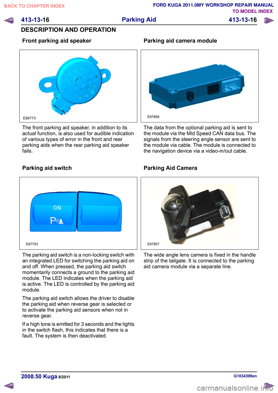
Front parking aid speaker
The front parking aid speaker, in addition to its
actual function, is also used for audible indication
of various types of error in the front and rear
parking aids when the rear parking aid speaker
fails.
Parking aid switch
The parking aid switch is a non-locking switch with
an integrated LED for switching the parking aid on
and off. When pressed, the parking aid switch
momentarily connects a ground to the parking aid
module. The LED indicates when the parking aid
is active. The LED is controlled by the parking aid
module.
The parking aid switch allows the driver to disable
the parking aid when reverse gear is selected or
to activate the parking aid sensors when not in
reverse gear.
If a high tone is emitted for 3 seconds and the lights
in the switch flash, this indicates that there is a
fault. The system is then deactivated. Parking aid camera module
The data from the optional parking aid is sent to
the module via the Mid Speed CAN data bus. The
signals from the steering angle sensor are sent to
the module via cable. The module is connected to
the navigation device via a video-in/out cable.
Parking Aid Camera
The wide angle lens camera is fixed in the handle
strip of the tailgate. It is connected to the parking
aid camera module via a separate line.
G1034399en
2008.50 Kuga 8/2011 413-13-16
Parking Aid
413-13-16
DESCRIPTION AND OPERATIONTO MODEL INDEX
BACK TO CHAPTER INDEX
FORD KUGA 2011.0MY WORKSHOP REPAIR MANUALE89773 E97703 E97856 E97857
Page 216 of 2057
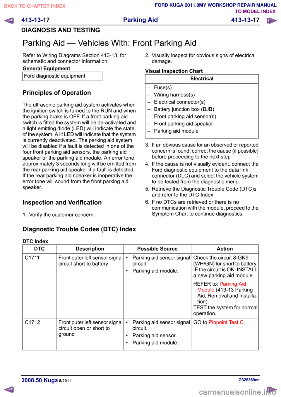
Parking Aid — Vehicles With: Front Parking Aid
Refer to Wiring Diagrams Section 413-13, for
schematic and connector information.
General Equipment
Ford diagnostic equipment
Principles of Operation
The ultrasonic parking aid system activates when
the ignition switch is turned to the RUN and when
the parking brake is OFF. If a front parking aid
switch is fitted the system will be de-activated and
a light emitting diode (LED) will indicate the state
of the system. A lit LED will indicate that the system
is currently deactivated. The parking aid system
will be disabled if a fault is detected in one of the
four front parking aid sensors, the parking aid
speaker or the parking aid module. An error tone
approximately 3 seconds long will be emitted from
the rear parking aid speaker if a fault is detected.
If the rear parking aid speaker is inoperative the
error tone will sound from the front parking aid
speaker.
Inspection and Verification
1. Verify the customer concern. 2. Visually inspect for obvious signs of electrical
damage.
Visual Inspection Chart Electrical
– Fuse(s)
– Wiring harness(s)
– Electrical connector(s)
– Battery junction box (BJB)
– Front parking aid sensor(s)
– Front parking aid speaker
– Parking aid module
3. If an obvious cause for an observed or reported concern is found, correct the cause (if possible)
before proceeding to the next step
4. If the cause is not visually evident, connect the Ford diagnostic equipment to the data link
connector (DLC) and select the vehicle system
to be tested from the diagnostic menu.
5. Retrieve the Diagnostic Trouble Code (DTC)s and refer to the DTC Index.
6. If no DTCs are retrieved or there is no communication with the module, proceed to the
Symptom Chart to continue diagnostics.
Diagnostic Trouble Codes (DTC) Index
DTC Index Action
Possible Source
Description
DTC
Check the circuit 8-GN9
(WH/GN) for short to battery.
IF the circuit is OK, INSTALL
a new parking aid module.
REFER to:Parking Aid
Module (413-13 Parking
Aid, Removal and Installa-
tion).
TEST the system for normal
operation.
• Parking aid sensor signal
circuit.
• Parking aid module.
Front outer left sensor signal
circuit short to battery
C1711
GO toPinpoint Test C.
• Parking aid sensor signal
circuit.
• Parking aid sensor.
• Parking aid module.
Front outer left sensor signal
circuit open or short to
ground
C1712 G325369en
2008.50 Kuga 8/2011 413-13-17
Parking Aid
413-13-17
DIAGNOSIS AND TESTINGTO MODEL INDEX
BACK TO CHAPTER INDEX
FORD KUGA 2011.0MY WORKSHOP REPAIR MANUAL
Page 218 of 2057
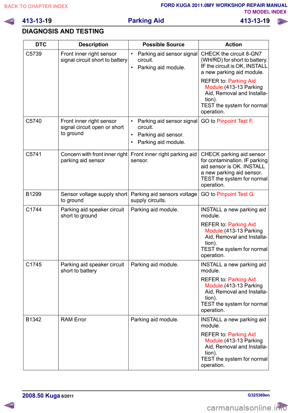
Action
Possible Source
Description
DTC
CHECK the circuit 8-GN7
(WH/RD) for short to battery.
IF the circuit is OK, INSTALL
a new parking aid module.
REFER to:Parking Aid
Module (413-13 Parking
Aid, Removal and Installa-
tion).
TEST the system for normal
operation.
• Parking aid sensor signal
circuit.
• Parking aid module.
Front inner right sensor
signal circuit short to battery
C5739
GO toPinpoint Test F.
• Parking aid sensor signal
circuit.
• Parking aid sensor.
• Parking aid module.
Front inner right sensor
signal circuit open or short
to ground
C5740
CHECK parking aid sensor
for contamination. IF parking
aid sensor is OK. INSTALL
a new parking aid sensor.
TEST the system for normal
operation.
Front inner right parking aid
sensor.
Concern with front inner right
parking aid sensor
C5741
GO toPinpoint Test G.
Parking aid sensors voltage
supply circuits.
Sensor voltage supply short
to ground
B1299
INSTALL a new parking aid
module.
REFER to:Parking Aid
Module (413-13 Parking
Aid, Removal and Installa-
tion).
TEST the system for normal
operation.
Parking aid module.
Parking aid speaker circuit
short to ground
C1744
INSTALL a new parking aid
module.
REFER to:Parking Aid
Module (413-13 Parking
Aid, Removal and Installa-
tion).
TEST the system for normal
operation.
Parking aid module.
Parking aid speaker circuit
short to battery
C1745
INSTALL a new parking aid
module.
REFER to:Parking Aid
Module (413-13 Parking
Aid, Removal and Installa-
tion).
TEST the system for normal
operation.
Parking aid module.
RAM Error
B1342 G325369en
2008.50 Kuga 8/2011 413-13-19
Parking Aid
413-13-19
DIAGNOSIS AND TESTINGTO MODEL INDEX
BACK TO CHAPTER INDEX
FORD KUGA 2011.0MY WORKSHOP REPAIR MANUAL