key FORD MUSTANG 1969 Volume One Chassis
[x] Cancel search | Manufacturer: FORD, Model Year: 1969, Model line: MUSTANG, Model: FORD MUSTANG 1969Pages: 413, PDF Size: 75.81 MB
Page 347 of 413

07-03-07
FMX Transmission
07-03-07
Gauge Pin
(No.
43 Drill)
NEUTRAL START
SWITCH
ADJUSTMENT
SCREWS
D 1759-A
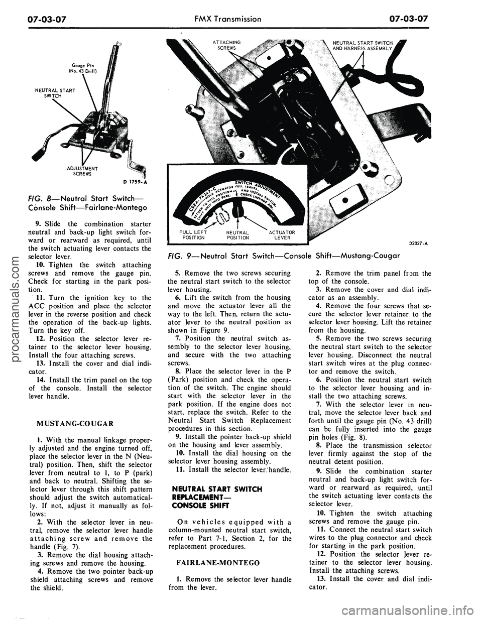
FIG. 8—
Neutral
Start Switch-
Console Shift—Fairlane-Montego
9. Slide the combination starter
neutral and back-up light switch for-
ward or rearward as required, until
the switch actuating lever contacts the
selector lever.
10.
Tighten the switch attaching
screws and remove the gauge pin.
Check for starting in the park posi-
tion.
11.
Turn the ignition key to the
ACC position and place the selector
lever in the reverse position and check
the operation of the back-up lights.
Turn the key off.
12.
Position the selector lever re-
tainer to the selector lever housing.
Install the four attaching screws.
13.
Install the cover and dial indi-
cator.
14.
Install the trim panel on the top
of the console. Install the selector
lever handle.
MUSTANG-COUGAR
1.
With the manual linkage proper-
ly adjusted and the engine turned off,
place the selector lever in the N (Neu-
tral) position. Then, shift the selector
lever from neutral to 1, to P (park)
and back to neutral. Shifting the se-
lector lever through this shift pattern
should adjust the switch automatical-
ly. If not, adjust it manually as fol-
lows:
2.
With the selector lever in neu-
tral,
remove the selector lever handle
attaching screw and remove the
handle (Fig. 7).
3.
Remove the dial housing attach-
ing screws and remove the housing.
4.
Remove the two pointer back-up
shield attaching screws and remove
the shield.
NEUTRAL START SWITCH
AND HARNESS ASSEMBLY
32027-A
FIG. 9—Neutral Start Switch—Console Shift—Mustang-Cougar
5.
Remove the two screws securing
the neutral start switch to the selector
lever housing.
6. Lift the switch from the housing
and move the actuator lever all the
way to the left. Then, return the actu-
ator lever to the neutral position as
shown in Figure 9.
7.
Position the neutral switch as-
sembly to the selector lever housing,
and secure with the two attaching
screws.
8. Place the selector lever in the P
(Park) position and check the opera-
tion of the switch. The engine should
start with the selector lever in the
park position. If the engine does not
start, replace the switch. Refer to the
Neutral Start Switch Replacement
procedures in this section.
9. Install the pointer back-up shield
on the housing and lever assembly.
10.
Install the dial housing on the
selector lever housing assembly.
11.
Install the selector lever.'handle.
NEUTRAL START SWITCH
REPLACEMENT-
CONSOLE SHIFT
On vehicles equipped with a
column-mounted neutral start switch,
refer to Part 7-1, Section 2, for the
replacement procedures.
FAIRLANE-MONTEGO
1.
Remove the selector lever handle
from the lever.
2.
Remove the trim panel from the
top of the console.
3.
Remove the cover and dial indi-
cator as an assembly.
4.
Remove the four screws that se-
cure the selector lever retainer to the
selector lever housing. Lift the retainer
from the housing.
5.
Remove the two screws securing
the neutral start switch to the selector
lever housing. Disconnect the neutral
start switch wires at the plug connec-
tor and remove the switch.
6. Position the neutral start switch
to the selector lever housing and in-
stall the two attaching screws.
7.
With the selector lever in neu-
tral,
move the selector lever back and
forth until the gauge pin (No. 43 drill)
can be fully inserted into the gauge
pin holes (Fig. 8).
8. Place the transmission selector
lever firmly against the stop of the
neutral detent position.
9. Slide the combination starter
neutral and back-up light switch for-
ward or rearward as required, until
the switch actuating lever contacts the
selector lever.
10.
Tighten the switch attaching
screws and remove the gauge pin.
11.
Connect the neutral start switch
wires to the plug connector and check
for starting in the park position.
12.
Position the selector lever re-
tainer to the selector lever housing.
Install the attaching screws.
13.
Install the cover and dial indi-
cator.procarmanuals.com
Page 375 of 413

07-04-06
C-6 Automatic Transmission
0704-06
TRANSMISSION
MANUAL LEVER
STUD-7B415
ENGAGE FLATS OF STUD IN SLOT OF
ROD BEFORE APPLYING TORQUE
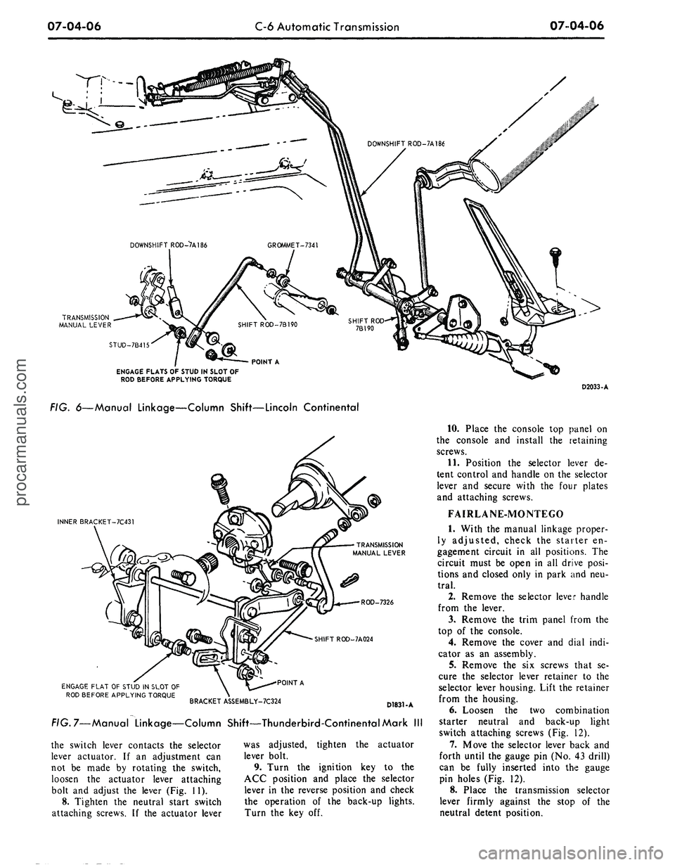
FIG. 6—Manual Linkage—Column Shift—Lincoln Continental
INNER BRACKET-7C431
TRANSMISSION
MANUAL LEVER
ROD-7326
SHIFT ROD-7A024
ENGAGE FLAT OF STUD IN SLOT
OF
ROD BEFORE APPLYING TORQUE
POINT A
BRACKET ASSEMBLY-7C324
D1831-A
FIG.
7—Manual
Linkage—Column Shift—Thunderbird-Continental Mark
III
the switch lever contacts
the
selector
lever actuator.
If an
adjustment
can
not
be
made
by
rotating
the
switch,
loosen
the
actuator lever attaching
bolt
and
adjust
the
lever (Fig.
11).
8. Tighten
the
neutral start switch
attaching screws.
If the
actuator lever
was adjusted, tighten
the
actuator
lever bolt.
9. Turn
the
ignition
key to the
ACC position
and
place
the
selector
lever
in the
reverse position
and
check
the operation
of the
back-up lights.
Turn
the key off.
D2033-A
10.
Place
the
console
top
panel
on
the console
and
install
the
retaining
screws.
11.
Position
the
selector lever
de-
tent control
and
handle
on the
selector
lever
and
secure with
the
four plates
and attaching screws.
FAIRLANE-MONTEGO
1.
With
the
manual linkage proper-
ly adjusted, check
the
starter
en-
gagement circuit
in all
positions.
The
circuit must
be
open
in all
drive posi-
tions
and
closed only
in
park
and neu-
tral.
2.
Remove
the
selector lever handle
from
the
lever.
3.
Remove
the
trim panel from
the
top
of the
console.
4.
Remove
the
cover
and
dial indi-
cator
as an
assembly.
5.
Remove
the six
screws that
se-
cure
the
selector lever retainer
to the
selector lever housing. Lift
the
retainer
from
the
housing.
6. Loosen
the two
combination
starter neutral
and
back-up light
switch attaching screws (Fig.
12).
7.
Move
the
selector lever back
and
forth until
the
gauge
pin
(No.
43
drill)
can
be
fully inserted into
the
gauge
pin holes (Fig.
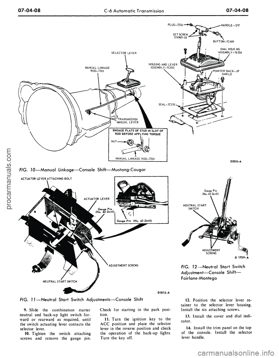
12).
8. Place
the
transmission selector
lever firmly against
the
stop
of the
neutral detent position.procarmanuals.com
Page 377 of 413

07-04-08
C-6 Automatic Transmission
07-04-08
PLUG-7256
•
•HANDLE-7217
I DIAL HOUS NG
ASSEMBLY-7E034
POINTER BACK-JP
SHIELD
HOUSING AND LEVER
ASSEMBLY-7C453
ENGAGE FLATS OF STUD IN SLOT OF
ROD BEFORE APPLYING TORQUE
D2034-A
FIG. 10—Manual Linkage—Console Shift—Mustang-Cougar
ACTUATOR LEVER ATTACHING BOLT
Gauge Pin
(No.
43 Drill)
NEUTRAL START
SWITCH
D1812-A
FIG. 11—Neutral Start Switch Adjustments—Console Shift
9. Slide the combination starter
neutral and back-up light switch for-
ward or rearward as required, until
the switch actuating lever contacts the
selector lever.
10.
Tighten the switch attaching
screws and remove the gauge pin.
Check for starting in the park posi-
tion.
11.
Turn the ignition key to the
ACC position and place the selector
lever in the reverse position and check
the operation of the back-up lights.
Turn the key off.
FIG. 72—Neutral Start Switch
Adjustment—Console Shift—
Fairlane-Montego
12.
Position the selector lever re-
tainer to the selector lever housing.
Install the six attaching screws.
13.
Install the cover and dial indi-
cator.
14.
Install the trim panel on the top
of the console. Install the selector
lever handle.procarmanuals.com