instrument panel FORD MUSTANG 1969 Volume One Chassis
[x] Cancel search | Manufacturer: FORD, Model Year: 1969, Model line: MUSTANG, Model: FORD MUSTANG 1969Pages: 413, PDF Size: 75.81 MB
Page 6 of 413
01-01-02
Vehicle Identification
01-01-02
VEHICLE WARRANTY NUMBER
The vehicle warranty number is the first line of numbers and
letters appearing on the Warranty Plates (Fig. 1). The Warranty
Plate is riveted to the left front door lock face panel. The first
number indicates the model year. The letter following the model
year number indicates the manufacturing assembly plant. The next
two numbers designate the Body Serial Code followed by a letter
expressing the Engine Code. The group of six digits remaining on
the first line indicate the Consecutive Unit Number.
VEHICLE DATA
The vehicle data appears on the second or lower line on the
Warranty Plate. The first two numbers and a letter identify the
Body Style. A letter or a number appears next indicating the
Exterior Paint Color followed by a number-letter combination
designating the Interior Trim. To the right of this code appears the
Date Code indicating the date the car was manufactured. A two-
digit number next designates the district in which the car was
ordered and may appear in conjunction with a Domestic Special
Order or Foreign Special Order number when applicable. The final
two spaces indicate the Rear Axle Ratio (numbers for regular axles,
letters for locking-types) and the Transmission type (numbers for
manual,
letters for automatic).
OFFICIAL VEHICLE IDENTIFICATION NUMBER
The official Vehicle Identification Number (VIN) for title and
registration purposes is stamped on an aluminum tab that is riveted
to the instrument panel close to the windshield on the driver's side
of the car and is visible from outside (Fig. 2).
MODEL YEAR CODE
The number 9 designates 1969.
ASSEMBLY PLANT CODES
COUGAR
Code
Letter
Code
Letter
A
B
C
D
E
F
G
H
J
K
Atlanta
L
Oakville (Canada)
N
Ontario Truck
P
Dallas
R
.,
Mahwah
S
Dearborn
T
Chicago
U
Lorain
W
Los Angeles
X
Kansas City
Y
Z
Michigan Truck
Norfolk
Twin Cities
San Jose
.
(Pilot). ...Allen Park
Metuchen
Louisville
Wayne
St. Thomas
Wixom
St. Louis
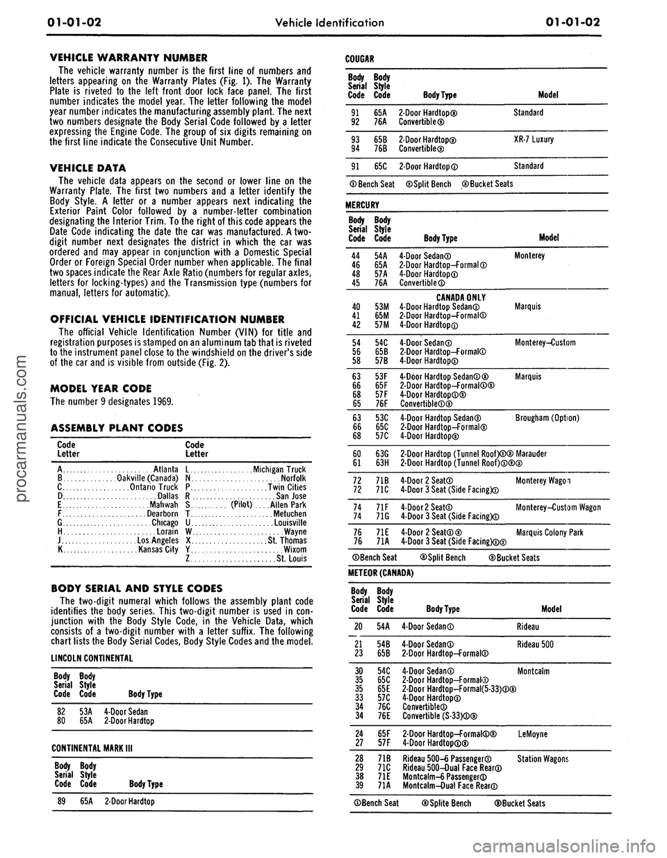
BODY SERIAL AND STYLE CODES
The two-digit numeral which follows the assembly plant code
identifies the body series. This two-digit number is used in con-
junction with the Body Style Code, in the Vehicle Data, which
consists of a two-digit number with a letter suffix. The following
chart lists the Body Serial Codes, Body Style Codes and the model.
LINCOLN CONTINENTAL
Body Body
Serial Style
Code Code Body Type
82
53A
4-Door Sedan
80
65A
2-Door
Hardtop
CONTINENTAL MARK
III
Body Body
Serial Style
Code Code Body Type
89
65A
2-Door
Hardtop
Body
Serial
Code
91
92
93
94
91
Body
Style
Code
65A
76A
65B
76B
65C
® Bench Seat
MERCURY
Body
Serial
Code
44
46
48
45
40
41
42
54
56
58
63
66
68
65
63
66
68
60
61
72
72
74
74
76
76
Body
Style
Code
54A
65A
57A
76A
53M
65M
57M
54C
65B
57B
53F
65F
57 F
76F
53C
65C
57C
63G
63H
71B
71C
71F
71G
71E
71A
©Bench Seat
Body
Type
2-Door
Hardtop©
Convertible©
2-Door
Hardtop©
Convertible®
2-Door
Hardtop®
Model
Standard
XR-7 Luxury
Standard
©Split Bench ©Bucket Seats
Body Type
4-Door Sedan©
2-Door
Hardtop-Formal®
4-Door Hardtop®
Convertible®
CANADA ONLY
4-Door Hardtop Sedan®
2-Door
Hardtop-Formal®
4-Door Hardtop®
4-Door Sedan®
2-Door
Hardtop-Formal®
4-Door Hardtop®
4-Door Hardtop Sedan®©
2-Door
Hardtop-Formal®©
4-Door Hardtop®®
Convertible®®
4-Door Hardtop Sedan©
2-Door
Hardtop-Formal©
4-Door Hardtop©
Model
Monterey
Marquis
Monterey-Custom
Marquis
Brougham (Option)
2-Door
Hardtop (Tunnel Roof)®© Marauder
2-Door
Hardtop (Tunnel Roof)®®©
4-Door 2 Seat®
4-Door 3 Seat (Side Facing)®
4-Door
2
Seat®
4-Door 3 Seat (Side Facing)®
4-Door 2 Seat®©
4-Door 3 Seat (Side Facing)®©
Monterey Wagoi
Monterey-Custom Wagon
Marquis Colony Park
©Split Bench ©Bucket Seats
METEOR (CANADA)
Body
Serial
Code
20
21
23
Body
Style
Code
54A
54B
65B
Body Type
4-Door Sedan®
4-Door Sedan®
2-Door
Hardtop-Formal®
Model
Rideau
Rideau 500
30
54C
4-Door Sedan®
35
65C
2-Door
Hardtop-Formal®
35
65E
2-Door
Hardtop-Formal{5-33)®®
33
57C
4-Door Hardtop®
34
76C
Convertible®
34
76E
Convertible (S-33)®®
Montcalm
24
65F
2-Door
Hardtop-Formal®©
27
57F
4-Door Hardtop®®
LeMoyne
28
71B
Rideau 500-6 Passenger®
29
71C
Rideau 500-Dual Face Rear®
38
71E
Mo ntcalm-6 Passenger®
39
71A
Montcalm-Dual Face Rear®
Station Wagons.
©Bench Seat ©Splite Bench ©Bucket Seatsprocarmanuals.com
Page 22 of 413
02-02-03
Brake System
02-02-03
DESCRIPTION
Disc brakes are available as option-
al equipment for the front wheels on
Ford, Mercury, Meteor, Fairlane,
Montego, Falcon, Mustang and Cou-
gar models and are standard on Thun-
derbird, Continental Mark III, and
Lincoln Continental models. The
dual-master cylinder equipped hydrau-
lic brake system employs single an-
chor, internal expanding and
self-
adjusting drum brake assemblies on
the rear wheels of vehicles with disc
brakes, and on the front and rear
wheels of all others.
A vacuum booster is used with the
power disc brake system.
DUAL MASTER CYLINDER
BRAKE SYSTEM
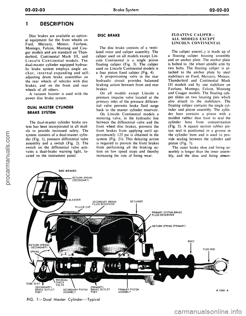
The dual-master cylinder brake sys-
tem has been incorporated in all mod-
els to provide increased safety. The
system consists of a dual-master cylin-
der (Fig. 1), pressure differential valve
assembly and a switch (Fig. 2). The
switch on the differential valve acti-
vates a dual-brake warning light, lo-
cated on the instrument panel.
DISC BRAKE
The disc brake consists of a venti-
lated rotor and caliper assembly. The
caliper used on all models except Lin-
coln Continental is a single piston
floating caliper (Fig. 3). The caliper
used on Lincoln Continental models is
a four piston fixed caliper (Fig. 4).
A proportioning valve in the rear
hydraulic circuit provides balanced
braking action between front and rear
brakes.
On all models except Lincoln a
pressure impulse valve located at the
primary inlet of the pressure differen-
tial valve prevents brake fluid surge
back to the master cylinder reservoir.
On Lincoln Continental models a
metering valve, in the hydraulic line
between the differential valve and the
front wheel disc brakes, prevents the
front brakes from applying until ap-
proximately 125 psi is obtained in the
system (Fig. 21). This delaying action
is required to prevent the front brakes
from performing all the braking ac-
tion on low speed stops and thereby
increasing the rate of lining wear.
FLOATING CALIPER—
ALL MODELS EXCEPT
LINCOLN CONTINENTAL
The caliper asseml.y is made up of
a floating caliper housing assembly
and an anchor plate. The anchor plate
is bolted to .the wheel spindle arm by
two bolts. The floating caliper is at-
tached to the anchor plate by steel
stabilizers on Ford, Mercury, Meteor,
Thunderbird and Continental Mark
III models and by one stabilizer on
Fairlane, Montego, Falcon, Mustang
and Cougar models. The floating cali-
per slides on two locating pins which
also attach to the stabilizers. The
floating caliper contains the single cyl-
inder and piston assembly. The cylin-
der bore contains a piston with a
molded rubber dust boot to seal the
cylinder bore from contamination
(Fig. 5). A square section rubber pis-
ton seal is positioned in a groove in
the cylinder bore and is used to pro-
vide sealing between the cylinder and
piston (Fig. 7).
The outer brake shoe and lining as-
sembly is longer than the inner assem-
bly, and the shoe and lining
DISC BRAKES
RETURN SPRING
(SECONDARY)
RETAINER
PRIMARY SYSTEM BRAKE
FLUID RESERVOIR
BOOT
PUSH ROD
TUBE SEAT |
(SECONDARY)
BRAKE OUTLET
PORT
RESIDUAL \ ^
CHECK \
VALVE \
SECONDARY PISTON
ASSEMBLY
(PRIMARY)
BRAKE OUTLET
PORT
PRIMARY PISTON
ASSEMBLY
H 1545-A
FIG.
I
—
Dual
Master Cylinder—Typicalprocarmanuals.com
Page 39 of 413
02-02-20
Brake System
02-02-20
1.
Disconnect the stoplight switch
wires at the connector. Remove the
spring retainer. Slide the stop light
switch off the brake pedal pin just far
enough to clear the end of the pin,
then liftfthe switch straight upward
from the pin. Use care to avoid switch
damage during removal.
2.
Slide the master cylinder push
rod and the nylon washers and bush-
ings off the brake pedal pin.
3.
Remove the brake tube from the
primary and secondary outlet ports of
the master cylinder.
4.
Remove the cap screws and lock-
washers that secure the master cylin-
der to the dirSh panel and lift the cyl-
inder forward and upward from the
vehicle.
Installation
1.
Position the boot on the push
rod and secure the boot to the master
cylinder. Carefully insert the master
cylinder push rod and boot through
the dash panel opening and position
the master cylinder on the panel.
2.
Install the cap screws at the dash
panel and torque them to specifica-
tion.
3.
Coat the nylon bushings with
SAE 10W oil. Install the nylon wash-
er and bushing on the brake pedal pin.
4.
Position the stop light switch on
the brake pedal pin, install the nylon
bushing and washer and secure them
in position with the spring retainer.
5.
Connect the wires at the stop
light switch connector.
6. Connect the brake lines to the
master cylinder leaving the brake line
fittings loose.
7.
Fill the master cylinder with the
specified brake fluid to within 1/4
inch of the top of the dual reservoirs.
Use Ford Brake Fluid— Extra Heavy
Duty-Part Number C6AZ-19542-A
(ESA-M6C25-A) or equivalent for all
drum brake applications. The extra
heavy duty brake system fluid is col-
ored blue for identification. Do not
mix low temperature brake fluids with
the specified fluid for the power disc
brake system.
8. Bleed the dual-master cylinder
and the primary and secondary brake
systems. Centralize the pressure dif-
ferential valve. Refer to Hydraulic
System Bleeding and Centralizing of
the Differential Valve, Part 2-1, Sec-
tion 2 for proper procedure.
9. Operate the brakes several times,
then check for external hydraulic
leaks.
FAIRLANE, MONTEGO,
FALCON, MUSTANG AND
COUGAR
Removal
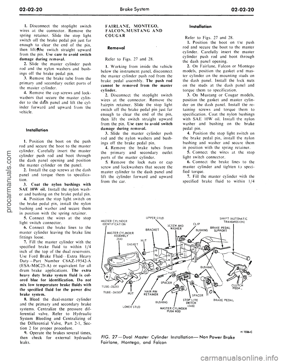
Refer to Figs. 27 and 28.
1.
Working from inside the vehicle
below the instrument panel, disconnect
the master cylinder push rod from the
brake pedal assembly. The push rod
cannot be removed from the master
cylinder.
2.
Disconnect the stoplight switch
wires at the connector. Remove the
hairpin retainer. Slide the stop light
switch off the brake pedal pin just far
enough to clear the end of the pin,
then lift the switch straight upward
from the pin. Use care to avoid switch
damage during removal.
3.
Slide the master cylinder push
rod and the nylon washers and bush-
ings off the brake pedal pin.
4.
Remove the brake tubes from
the primary and secondary outlet
ports of the master cylinder.
5.
Remove the lock nuts or cap
screw and lockwashers that secure the
master cylinder to the dash panel and
lift the cylinder forward and upward
from the car.
Installation
Refer to Figs. 27 and 28.
1.
Position the boot on tie push
rod and secure the boot to the master
cylinder. Carefully insert the master
cylinder push rod and boot through
the dash panel opening.
2.
On Fairlane, Falcon or Montego
models, position the gasket and mas-
ter cylinder on the mounting studs on
the dash panel. Install the lock nuts
on the studs at the dash panel and
torque them to specification.
3.
On Mustang or Cougar models,
position the gasket and master cylin-
der on the dash panel. Install the re-
taining screws and torque them to
specification. Coat the nylon bushings
with SAE 10W oil. Install the nylon
washer and bushing on the brake
pedal pin.
4.
Position the stop light switch on
the brake pedal pin, install the nylon
bushing and washer and secure them
in position with the spring retainer.
5.
Connect the wires at the stop
light switch connector.
6. Connect the brake lines to the
master cylinder and tighten to speci-
fied torque.
7.
Fill the master cylinder with the
specified brake fluid to within 1/4
MASTER CYLINDER
IDENTIFICATION
UPPER STUD
SHAFT (AUTOf/lATIC
TRANSMISSION)
CLIP
BRAKE PEDAL
BUSHING SUPPORT
TUBE-2B253
TUBE-2A040
CLUTCH
PEDA_
LOWER STUD
STOP LITE
SWITCH
/ 13480
MASTER CYLINDER
PUSH ROD
BRAKE PEDAL
H 1556-C
FIG. 27—Dual Master Cylinder Installation—Non Power Brake
Fairlane, Montego, and Falconprocarmanuals.com
Page 43 of 413
02-02-24
Brake
System
02-02-24
proportioning valve to the fender
apron and remove the proportioning
valve.
Installation
1.
Position the proportioning valve
to the fender apron.
2.
Connect the two brake lines at
the proportioning valve. Do not tight-
en.
3.
Install the bolt retaining the pro-
portioning valve to the fender apron.
4.
Tighten the brake line tube nuts
at the proportioning valve to specifica-
tions.
5.
Bleed the brakes and centralize
pressure differential valve.
THUNDERBIRD AND
CONTINENTAL MARK III
Removal
Refer to Fig. 20.
1.
Disconnect the two hydraulic
brake lines at the master cylinder.
2.
Remove the two nuts retaining
the master cylinder to the booster and
remove the master cylinder for clear-
ance.
3.
Disconnect the two brake lines at
the proportioning valve.
4.
Remove the bolt and nut retain-
ing the proportioning valve to the
pressure differential valve bracket and
remove the proportioning valve assem-
bly.
Installation
1.
Transfer the bracket to the new
proportioning valve.
2.
Position the proportioning valve
assembly to the pressure differential
valve bracket.
3.
Connect the two brake lines to
the proportioning valve. Do not tight-
en.
4.
Install the bolt and nut retaining
the proportioning valve to the pressure
differential valve bracket.
5.
Tighten the two brake line tube
nuts at the proportioning valve to
specifications.
6. Position the master cylinder to
the booster and install the nuts retain-
ing the master cylinder to the booster.
7.
Connect the two brake lines at
the master cylinder and tighten the
tube nuts to specifications.
8. Bleed the brakes and centralize
the pressure differential valve.
LINCOLN CONTINENTAL
Removal
Refer to Fig. 21.
1.
Disconnect the two brake lines at
the proportioning valve.
2.
Loosen the bolt and nut on the
bracket retaining the proportioning
valve to the chassis.
3.
Remove the proportioning valve
from the bracket.
Installation
- 1. Position the proportioning valve
in the bracket and connect the two
brake lines. Do not tighten.
2.
Tighten the bolt and nut on the
bracket.
3.
Tighten the tube nuts on the
brake lines at the proportioning valve
to specifications.
4.
Bleed the brakes and centralize
the pressure differential valve.
PRESSURE METERING VALVE—
LINCOLN CONTINENTAL
REMOVAL
Refer to Fig. 21.
1.
Loosen the tube nuts connecting
the inlet and outlet tubes at the me-
tering valve, and remove the tubes.
2.
Remove the two screws retaining
the metering valve to the frame
crossmember, and remove the me-
tering valve. The metering valve is ser-
viced as an assembly only.
INSTALLATION
1.
Position the metering valve to
the frame crossmember, and install
the retaining screws.
2.
Connect the inlet and outlet
tubes to the metering valve, and tight-
en the tube nuts to specification.
BRAKE BOOSTER
REMOVAL
1.
Working from inside the\ vehicle
below the instrument panel, disconnect
the booster push rod from the brake
pedal assembly. To do this, proceed as
follows:
Disconnect the stop light switch
wires at the connector. Remove the
hairpin retainer. Slide the stop light
switch off from the brake pedal pin
just far enough for the switch outer
hole to clear the pin, and then remove
the switch from the pin and booster
push rod. Be careful not to damage
the switch during removal. Slide the
booster push rod and the nylon wash-
ers and bushing off the brake pedal
pin (Figs. 29 thru 33).
2.
Open the hood and remove the
master cylinder from the booster. Se-
cure it to one side without disturbing
the hydraulic lines. It is not necessary
to disconnect the brake lines, but care
should be taken that the brake lines
are not deformed. Permanent defor-
mation of brake lines can lead to tube
failure.
3.
Disconnect the manifold vacuum
hose or hoses from the booster unit.
4.
Remove the booster-to-dash
panel attaching nuts or bolts (Figs. 29
thru 33). Remove the booster and
bracket assembly from the dash panel,
sliding the push rod link out from the
engine side of the dash panel.
5.
On Fairlane, Montego, and Fal-
con models, remove the push rod link
boot from the dash panel.
INSTALLATION
1.
On Fairlane, Montego and Fal-
con models, install the push rod link
boot in the hole in the dash panel as
shown in Fig. 23. Install the four
spacers on the mounting studs.
2.
Mount the booster and bracket
assembly to the dash panel by insert-
ing the push rod or push rod link in
through the hole and boot in the dash
panel. Install the bracket-to-dash
panel attaching lock nuts or bolts
(Figs.
29 thru 33).
3.
Connect the manifold vacuum
hose or hoses to the booster.
4.
Before installing the master cyl-
inder, check the distance from the
outer end of the booster assembly
push rod to master cylinder surface.
Turn the screw in or out to obtain the
specified length. Refer to Part 2-1,
Section 2, Power Brake Master Cylin-
der Push Rod Adjustment. Install the
master cylinder and torque the attach-
ing nuts to specifications.
5.
Working from inside the vehicle
below the instrument panel, connect
the booster push rod link to the brake
pedal assembly. To do this, proceed as
follows:
Install the inner nylon washer, the
booster push rod, and the bushing on
the brake pedal pin. Position the
switch so that it straddles the push
rod with the switch slot on the pedal
pin and the switch outer hole justprocarmanuals.com
Page 46 of 413
02-02-27
Brake System
02-02-27
4.
Connect the stop light switch
wires to the connector, and install the
wires in the retaining clip.
5.
Torque the booster mounting
nuts to specifications.
LINCOLN CONTINENTAL
Removal
1.
Disconnect the battery ground
cable from the battery.
2.
It is necessary to obtain clear-
ance to remove vacuum hoses and the
electrical connector to the temperature
heat control box. Remove the two
screws retaining the relay to the fend-
er and push the relay aside. Discon-
nect the vacuum hoses and connector
at the heat control box.
3.
Working under the instrument
panel, disconnect the vacuum hoses,
wires and retaining clip from the tem-
perature heat control box. Remove the
two screws securing the temperature
control box to the dash panel.
4.
Remove the lower control hous-
ing retaining screws (6). Disconnect
the wire harnesses at the lower control
panel and place the panel aside. Re-
move the wire harness shield. Remove
the wire harness clip. Position the
wire harness aside. Remove the tem-
perature control box and position it
aside.
5.
Remove the hair-pin type retain-
er. Slide the stop light switch off the
brake pedal pin just far enough for
the switch outer hole to clear the pin.
Lift the switch upward from the pin.
Slide the master cylinder push rod,
nylon washers and bushing off the
brake pedal pin.
6. Remove the pivot bolt and nut
that holds the pedal to the pedal sup-
port bracket. Remove the brake pedal
assembly from the support bracket
and remove the bushings.
7.
If required, remove the brake
pedal pad retaining nuts and remove
the brake pedal pad.
Installation
1.
If the brake pedal pad was re-
moved, position the pad on the pedal.
Install the pad retaining nuts and tor-
que them to specification.
2.
Apply SAE 10 engine oil to the
bushings and locate all the bushings in
their proper places on the pedal as-
sembly.
3.
Install the brake pedal assembly
and bushings to the support bracket,
and then install the pivot bolt through
the support bracket and pedal assem-
bly. Install the pivot bolt nut and tor-
que it to specification.
4.
Install the inner nylon washer,the
master cylinder push rod link, and the
bushing on the brake pedal pin. Posi-
tion the switch so that it straddles the
push rod link with the switch slot on
the pedal and the switch outer hole
just clearing the pin. Install the outer
nylon washer as shown in Fig. 33. In-
stall the hair-pin type retainer on the
brake pedal pin.
5.
Connect the stop light switch
wires to the connector, and install the
wires in the retaining clip.
6. Position the wire harness and
clip on the temperature control box
and install the retaining screw. Posi-
tion the temperature control box to
the dash panel and install the two re-
taining bolts.
7.
Connect the vacuum lines and
the electrical connector to the control
box. Position the wire harness to the
control box and install the retaining
clip.
8. Position the wire harness shield
and install two retaining bolts.
9. Connect the wire harnesses to
the lower control panel and install the
retaining screws.
10.
Working within the engine
compartment, connect the wire con-
nector to the temperature heat control
box.
11.
Position the relay to the fender
apron and install the retaining bolts.
12.
Connect the ground cable to the
battery.
13.
Check the brakes and light
switch for proper operation. Close the
hood.
PARKING BRAKE CONTROL
ASSEMBLY
FORD, MERCURY
AND METEOR
Removal
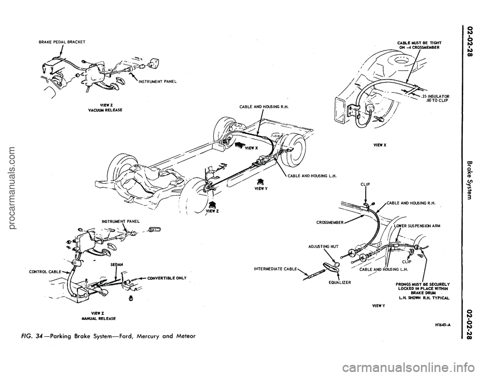
Refer to Fig. 34.
1.
Make sure the parking brake is
fully released.
2.
Remove all tension from the rear
cables by backing off the adjusting nut
from the equalizer.
3.
Remove the roll pin that secures
the release knob to the cable and re-
move the knob.
4.
Remove the nut that secures the
release cable to the instrument panel
and remove the cable from the rear of
the instrument panel.
5.
Remove the two nuts attaching
the control assembly to the dash
panel.
6. Remove the cap screw attaching
the control assembly to the cowl side
bracket.
7.
Disconnect the hose to the park-
ing brake vacuum unit, if so equipped.
8. Remove the front cable assembly
retainer clip from the cable assembly
and disconnect the cable ball from the
control clevis.
9. Remove the control assembly
from the vehicle.
Installation
1.
Position the control assembly in
the vehicle.
2.
Fit the cable assembly through
its mounting hole and install the re-
taining clip. Connect the cable ball to
the control clevis.
3.
Connect the vacuum hose to the
parking brake unit, if so equipped.
4.
Install the attaching cap screw to
the cowl side bracket. Do not tighten.
5.
Install the two control assemb-
ly-to-dash panel nuts. Tighten the nuts
and the cap screw to specifications.
6. Insert the release cable into the
instrument panel and install the re-
taining nut.
7.
Install the release knob on the
cable with the roll pin.
8. Check the operation of the park-
ing brake. Adjust the parking brake
as required.
FAIRLANE, MONTEGO
AND FALCON
Removal
Refer to Fig. 35.
1.
Make sure the parking brake is
completely released.
2.
Remove all tension from the rear
cables by backing off the jam nut and
adjusting nut from the equalizer.
3.
Working inside the vehicle, re-
move the four bolts and one nut re-
taining the left air vent and cable as-
sembly to the dash and instrument
panels. Remove the vent assembly.
4.
Remove the parking brake front
cable ball retaining clip from the clev-
is.
5.
Disconnect the cable ball from
the notch in the brake clevis.
6. Remove the three screws that at-
tach the control assembly to the left
cowl inner side panel.procarmanuals.com
Page 47 of 413
BRAKE PEDAL BRACKET
CABLE MUST BE TIGHT
ON -4 CROSSMEMBER
INSTRUMENT PANEL
VIEWZ
VACUUM RELEASE
INSTRUMENT PANEL
CONTROL CABLE
CABLE AND HOUSING R.H.
.25 INSULATOR
.00 TO CLIP
VIEWX
CABLE AND HOUSING L.H.
CLIP
CROSSMEMBER
CABLE AND HOUSING R.H.
LOWER SUSPENSION ARM
INTERMEDIATE CABLE
CONVERTIBLE ONLY
EQUALIZER
VIEWY
VIEWZ
MANUAL RELEASE
PRONGS MUST BE SECURELY
LOCKED IN PLACE WITHIN
BRAKE DRUM
L.H. SHOWN R.H. TYPICAL
H1645-A
FIG. 34—Parking Brake System—Ford, Mercury and Meteorprocarmanuals.com
Page 49 of 413
02-02-30
Brake System
02-02-30
7.
Disconnect the wire lead at the
parking brake warning light switch
and remove the control assembly.
Installation
1.
Connect the wire lead to the
parking brake warning light switch.
2.
Position the control assembly to
the cowl inner side panel and install
the three attaching screws.
3.
Connect the ball-end of the park-
ing brake front cable assembly to the
control assembly, and install the hair-
pin retainer.
4.
Position the cable ball in the
notch in the brake clevis.
5.
Position the left air vent assem-
bly to the dash and instrument panels.
Install the four bolts and one nut re-
taining the air vent to the panels.
6. Check the operation of the park-
ing brake. Adjust the parking brake.
MUSTANG AND COUGAR
Removal
Refer to Fig. 36.
1.
Make sure the parking brake is
completely released,
2.
Remove all tension from the rear
cables by backing off the jam nut and
adjusting nut from the equalizer.
3.
Disconnect the wire lead at the
parking brake warning light switch (if
so equipped).
4.
Remove the parking brake front
cable ball retaining clip from the clev-
is.
5.
Remove the parking brake warn-
ing light switch and attaching screw (if
so equipped).
6. Disconnect the cable ball from
the notch in the brake clevis.
7.
Remove the three screws that at-
tach the control assembly to the left
cowl inner side panel.
8. Pull the control away from the
cowl, panel. Remove the hair-pin re-
tainer securing the front cable assem-
bly to the control assembly. Remove
the control assembly
Installation
1.
Connect the ball-end of the park-
ing brake front cable assembly to the
control assembly, and install the hair-
pin retainer.
2.
Position the control assembly to
the cowl inner side panel and install
the three attaching screws.
3.
Position the parking brake warn-
ing light switch and install the attach-
ing screw. Connect the parking brake
warning light switch wire lead (if vehi-
cle is so equipped).
4.
Position the cable ball in the
notch in the brake clevis.
5.
Check the operation of the park
ing brake. Adjust the parking brake.
THUNDERBIRD AND
CONTINENTAL MARK III
Removal
Refer to Fig. 37.
1.
Remove the two nuts retaining
the control to the dash panel.
2.
Remove two screws from the left
scuff plate.
3.
Remove one screw retaining the
left cowl trim panel and remove the
panel.
4.
Remove the two screws retaining
the left air duct and remove the air
duct.
5.
Remove the two screws retaining
the dimmer switch and position the
switch out of the way.
6. Remove the clip retaining the
cable assembly to the control.
7.
Disconnect the cable ball from
the control clevis.
8. Disconnect the vacuum hose at
the brake release.
9. Remove the bolt retaining the
control to the cowl side bracket and
remove the control.
Installation
1.
Position the parking brake con-
trol in the vehicle.
2.
Install the cable assembly in the
control and connect the cable ball to
the control clevis.
3.
Install the clip retaining the
cable to the control.
4.
Install the bolt retaining the con-
trol to the cowl side bracket.
5.
Connect the vacuum hose to the
parking brake release vacuum motor.
6. Position the dimmer switch and
install the retaining screws.
7.
Position the air duct and install
the retaining screws.
8. Position the cowl trim panel and
install the retaining screw.
9. Install the two scuff plate screws.
10.
Install the two nuts retaining
the control to the dash panel.
11.
Adjust the parking brakf
LINCOLN CONTINENTAL
Removal
Refer to Fig. 38.
1.
Raise the vehicle on a hoist.
2.
Loosen the parking brake cable
adjusting nut, remove the return
spring and remove the cable ball end
from the equalizer.
3.
Lower the vehicle.
4.
Disconnect the battery.
5.
Disconnect the wire harness con-
nector and two vacuum hoses at the
Automatic Temperature Control box.
6. Working inside the vehicle, re-
move the windshield wiper control
knob and bezel from the lower control
panel.
7.
Remove the screws retaining the
lower control panel. Lower the control
panel and disconnect wire harnesses
and vacuum hoses. Position the con-
trol panel aside.
8. Remove the screw retaining the
plastic wire cover and place 'the cover
aside.
9. Disconnect three vacuum hoses
and the wiring harness at the Auto-
matic Temperature Control box.
10.
Remove the two screws retain-
ing the Automatic Temperature Con-
trol box to the dash panel and remove
the box for clearance.
11.
Disconnect the ball end of the
cable from the control clevis.
12.
Remove the four bolts retaining
the control to the dash panel and
lower instrument panel flange.
13.
Disconnect the vacuum release
hose from the control and remove the
control assembly from the vehicle.
Installation
1.
Position the control assembly to
the dash panel and instrument panel
flange and install the four retaining
screws.
2.
Connect the vacuum release hose
to the control assembly.
3.
Connect the cable ball to the
control clevis.
4.
Position the Automatic Temper-
ature Control box to the dash panel
and install the retaining screws.
5.
Connect the wiring harness and
vacuum hoses to the Automatic Tem-
perature Control box.
6. Position the plastic wire covei
and install the retaining screw.
7.
Connect the wire harnesses and
vacuum lines to the lower control
panel and position the panel to the inprocarmanuals.com
Page 118 of 413
03-05-05
Steering Columns And Linkage
03-05-05
TILT-AWAY STEERING
COLUMN REPAIRS
VACUUM RELEASE VALVE-
COUGAR AND MUSTANG
Removal
1.
Working from the underside of
the instrument panel disconnect the
hose from the valve.
2.
Disconnect the wire from the
connector on the valve and the con-
nector from the relay.
3.
Remove the bracket-
to-instrument panel attaching bolt and
let the bracket swing down.
4.
Remove the two screws that se-
cure the valve to the mounting bracket
and remove the valve.
Installation
1.
Secure the valve to the mounting
bracket with the two attaching screws.
2.
Position the bracket to the in-
strument panel and install the attach-
ing bolt.
3.
Connect the wire to the terminal
on the valve.
4.
Connect the hose from the vacu-
um motor to the horizontal connector
on the valve and the hose from the
reservoir to the vertical connector.
VACUUM RELEASE VALVE—
THUNDERBIRD
Removal
1.
Remove the lower finish panel.
2.
Disconnect the vacuum hose
from the vacuum release valve.
3.
Disconnect the vacuum release
valve electrical leads at the connector.
4.
Loosen the two attaching screws
holding the bracket to the dash. Lift
up the bracket to clear the screws and
swing it down below the panel.
5.
Remove the screws attaching the
valve to the panel and remove the
valve.
Installation
1.
Position the vacuum release
valve on the bracket.
2.
Install the two attaching screws
and swing the bracket up and over the
screws. Tighten the screws.
3.
Connect the electrical leads to
the wiring harness.
4.
Connect the hose from the vacu-
um dash panel junction block to the
connector on the vacuum release valve
that points downward and forward.
Connect the hose from the vacuum
motor to the other connector on the
release valve.
5.
Install the lower finish panel.
VACUUM MOTOR-
COUGAR AND MUSTANG
Removal
1.
Working from the underside of
the instrument panel, disconnect the
hose to the valve and the wires to the
relay and valve.
2.
Remove the bracket-
to-instrument panel attaching bolt and
swing the bracket downward.
3.
Remove the clevis pin that se-
cures the cable to the vacuum motor
rod.
4.
Disconnect the starter safety
switch wire at the connector.
5.
Remove the two motor-
to-bracket attaching screws and re-
move the motor, disconnecting the
hose to the solenoid.
Installation
1.
Position the motor on the
mounting bracket and the attaching
screws.
2.
Connect the control cable to the
vacuum motor rod with the clevis pin.
3.
Position the bracket to the in-
strument panel and install the attach-
ing bolt. Make all electrical and vacu-
um connections.
4.
Readjust the cable bracket to as-
sure full engagement of the locking
pawl when in driving position.
5.
Connect the hose to the vacuum
motor.
VACUUM MOTOR—
THUNDERBIRD
Removal
1.
Remove the lower finish panel.
2.
Disconnect the vacuum hose
from the solenoid valve. Disconnect
the electrical lead.
3.
Loosen the screws that attach
the bracket to the dash and lift the
bracket up; then, swing it down.
4.
Remove the clevis pin holding
the motor to the cable.
5.
Remove the two attaching
screws, then lift the motor from the
bracket.
C-CLAMP
PIVOT PIN
G 1462-A
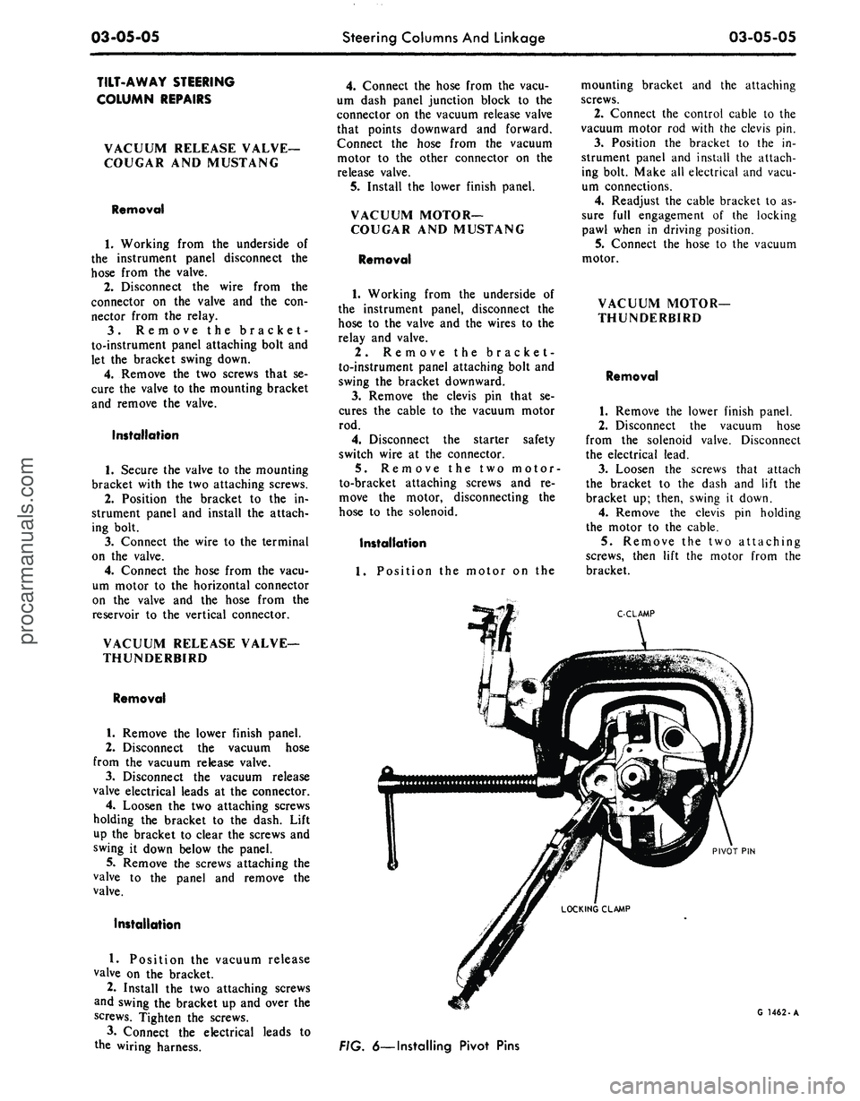
FIG. 6—Installing Pivot Pinsprocarmanuals.com
Page 119 of 413
03-05-06
Steering Columns And Linkage
03-05-06
Installation.
1.
Position the vacuum motor on
the bracket. Tighten the two attaching
screws.
2.
Connect the cable to the motor
with the clevis pin. Adjust the cable
bracket so the motor rod is fully ex-
tended, but not tight.
3.
Slide the vacuum motor as re-
quired to align the locking pawl rod
and vacuum motor. Retighten the two
vacuum motor attaching screws.
4.
Connect the vacuum hose to the
vacuum motor.
5.
Install the lower finish panel.
LOCKING LEVER
REPLACEMENT
Removal
1.
Remove the upper flange and
bearings from the column.
2.
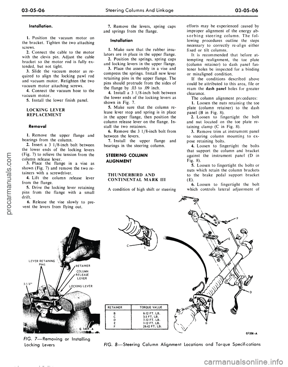
Insert a 3
1/8-inch
bolt between
the lower ends of the locking levers
(Fig. 7) to relieve the tension from the
column release lever.
3.
Place the flange in a vise as
shown (Fig. 7) and remove the two re-
tainers with a screwdriver.
4.
Lift the column release lever
from the flange.
5.
Drive the locking lever retaining
pins from the flange with a small
drift.
6. Release the vise slowly to pre-
vent the levers from flying out.
LEVER RETAINING
PINS
3-1/8'
7.
Remove the levers, spring caps
and springs from the flange.
Installation
1.
Make sure that the rubber insu-
lators are in place in the upper flange.
2.
Position the springs, spring caps
and locking levers in the upper flange.
3.
Place the assembly in a vise and
compress the springs. Install new lever
retaining pins in the upper flange. The
pins should protrude from the sides of
the flange by .03 to .09 inch.
4.
Install a 3
1/8-inch
bolt between
the lower ends of the locking levers as
shown in Fig. 7.
5.
Make sure that the column re-
lease lever stop and spring is in place
in the upper flange, then position the
column release lever on the flange. In-
stall the two retainers.
6. Remove the 3
1/8-inch
bolt from
between the levers.
7.
Install the upper flange and
bearings in the steering column.
STEERING COLUMN
ALIGNMENT
THUNDERBIRD AND
CONTINENTAL MARK III
A condition of high shift or steering
efforts may be experienced caused by
improper alignment of the energy ab-
sorbing steering column. The fol-
lowing procedures outline the steps
necessary to correctly re-align either
fixed or tilt columns.
It is recommended that before at-
tempting realignment, the toe plate
(column retainer) to dash panel fas-
tener holes be inspected for a binding
or misaligned condition.
If the conditions described above
could be attributed to this area, file or
ream the dash panel holes for greater
clearance.
The column alignment procedures:
1.
Loosen the nuts retaining the toe
plate (column retainer) to the dash
panel (B in Fig. 8).
2.
Loosen to fingertight the bolt
and nut located on the toe plate re-
taining clamp (C in Fig. 8).
3.
Remove trim at instrument panel
to steering column mounting to ex-
pose retaining bolts.
4.
Loosen to fingertight {.he bolts
that support the column and bracket
against the instrument panel (D in
Fig. 8).
5.
Loosen to fingertight the bolts or
nuts which retain the column brackets
to the brake pedal support bracket
(E).
6. Loosen to fingertight the bolt
which controls lateral adjustment of
RETAINER
B
c
D
E
F
TORQUE VALUE
8-12 FT. LB.
3-5 FT. LB.
7.12 FT. LB.
7.12 FT. LB.
28-42 FT. LB.
G1536-A
FIG. 7—Removing or Installing
Locking Levers
FIG. 8—Steering Column Alignment Locations and Torque Specificationsprocarmanuals.com
Page 121 of 413
03-05-08
Steering Columns And Linkage
03-05-08
tube.
In some instances the column
will shift into proper alignment when
the toe plate attaching nuts are loos-
ened. (Alignment is acceptable if a
.010 inch feeler blade can be passed
freely, completely around the area be-
tween the outer diameter of the steer-
ing shaft and the shift tube.) if the
misalignment condition can be attrib-
uted to this area, file or ream the dash
panel holes for greater clearance. If
the alignment is maintained after the
toe plate nuts and toe plate to column
clamp bolt and nut are torqued to the
8-12 ft-lb specification, no further ad-
justment is necessary.
4.
Remove instrument panel lower
trim panel. Vehicles equipped with a
combination radio stereo tape player
will require removal of the radio and
tape player assembly in order to gain
access to the upper R.H. steering col-
umn support bracket bolt.
5.
Loosen the seven bolts at the
steering column support bracket and
brake pedal support bracket.
6. Install a 3/16 inch diameter rod
spacer in the flex coupling to assure
proper clearance between upper and
lower steering shaft.
7.
Raise the vehicle, remove the
transmission splash shield, and visual-
ly align the column to center the
steering shaft in the column. Tighten
two toe plate attaching nuts sufficient-
ly to hold the column alignment (two
persons may be required for this oper-
ation).
8. Lower the vehicle.
9. Check the clearance between the
steering column support bracket and
the instrument panel bracket. It may
be necessary to add shims (Part Num-
ber MK-3054-A .060 inch thick, or
C3AZ-3054-A, .113 inch thick) be-
tween the support bracket and the in-
strument panel bracket to prevent
movement of the column when the
support bracket bolts are tightened.
10.
Loosen the two toe plate at-
taching nuts previously tightened. Re-
check steering column alignment. In
some instances it may be necessary to
enlarge the holes in the dash panel in
order to obtain proper column align-
ment.
11.
With the column properly al-
igned, torque the four toe plate at-
taching nuts to 4-9 ft-lbs.
12.
Torque the toe plate to steering
column clamp bolt to 3-5 ft-lbs.
13.
Recheck steering shaft to shift
tube alignment. A 0.10 inch feeler
blade should pass freely, completely
around the area between the outer di-
ameter of the steering shaft and shift-
er tube.
14.
Raise the vehicle.
15.
Adjust transmission shift link-
age.
16.
Install transmission splash
shield.
17.
Lower the vehicle.
18.
Install the radio stereo tape
player if so equipped.
19.
Install instrument panel lower
trim panel.
20.
Connect the battery.
REMOVAL AND INSTALLATION
STEERING COLUMN
FORD, MERCURY, METEOR
Removal
1.
Disconnect the battery cable
from the negative post.
2.
Disconnect the turn signal switch
wires at the connector.
3.
Disconnect the neutral start
switch and back-up light switch wires
from the switches.
4.
Disconnect the transmission con-
trol rod(s) from the lever(s) at the
lower end of the column.
5.
Remove the bolt that secures the
flex coupling to the steering gear.
6. Remove the nuts that secure the
column retainer and seal at the toe
plate (Fig. 11).
7.
Ford, Meteor: Remove the two
screws that secure the lower trim
shroud to the upper trim shroud. Re-
move the two shrouds.
Mercury: Remove the two screws
that secure the lower trim shroud to
the upper trim shroud. Remove the
top shroud Disconnect the ignition
switch light bulb. Remove the ignition
and light switch bezels and spring clip
and remove the lower shroud. Discon-
nect the light switch electrical connec-
tor block.
8. Remove the two screws that se-
cure the intermediate bracket to the
column lower bracket.
9. While supporting the steering
column, remove the two nuts that se-
cure the column lower bracket to the
instrument panel. Remove the brack-
ets.
10.
Lift the steering column and
wheel from the vehicle.
Installation
1.
Position the steering column in
the vehicle. Index the block tooth on
the steering gear shaft with the corre-
sponding slot on the flex coupling. In-
stall and tighten the flex coupling-
to-steering gear attaching bolt.
2.
Place the column upper bracket
and column lower bracket in position
on the column and install but do not
tighten the four attaching nuts.
3.
Install and tighten the two nuts
that secure the column lower bracket
to the instrument panel. Make certain
the column is properly positioned rela-
tive to the flex coupling input shaft
connection.
4.
Install and tighten the screws
that secure the intermediate bracket to
the column lower bracket.
5.
Tighten the four attaching nuts
at the upper and lower brackets and
the two nuts at the upper bracket to
instrument panel. The dial pointer (if
so equipped) should be adjusted to
coincide with the selector lever.
6. Install and tighten the nuts and
bolts that secure the column retainer
and seal at the toe plate. Make sure
the steering shaft is centered in the
column before tightening the nuts.
7.
Ford, Meteor: Install and tighten
the two screws that secure the lower
trim shroud to the upper trim shroud.
Mercury: Connect the light switch
harness block. Install the ignition and
light switch bezels. Connect the igni-
tion switch light bulb. Install the top
shroud and the two screws that secure
the lower trim shroud to the upper
shroud.
8. Connect the transmission control
rod(s) to the lever(s) at the lower end
of the column.
9. Connect the neutral start switch
and back-up light switch to their re-
spective terminals.
10.
Connect the turn signal switch
wires.
11.
Connect the negative battery
cable to the battery.
12.
Check the operation of the
steering tilt mechanism if so equipped
and the switches.procarmanuals.com