brake rotor FORD MUSTANG 1969 Volume One Chassis
[x] Cancel search | Manufacturer: FORD, Model Year: 1969, Model line: MUSTANG, Model: FORD MUSTANG 1969Pages: 413, PDF Size: 75.81 MB
Page 96 of 413

03-02-20
Suspension
03-02-20
hub and rotor on the spindle. Position
the caliper over the rotor and install
the attaching bolts. Torque the bolts
to specification (Part 3-13). Install the
wheel and tire on the hub and adjust
the wheel bearings as outlined in Part
3-12 .
7.
Install the hub cap or wheel
cover. Then, remove the support stand
and lower the vehicle.
8. Check caster, camber, and toe-in
(Part 3-1) and adjust as necessary.
COUGAR, FAIRLANE,
FALCON, MONTEGO,
MUSTANG
Drum Brakes
Removal
1.
Position a support between the
upper arm and frame as shown in
Figs.
8 and 9; then, raise the vehicle
and position safety stands.
2.
Remove the hub cap or wheel
cover.
3.
Remove the grease cap from the
hub;
then, remove the adjusting nut,
washer, and outer bearing cone and
roller assembly.
4.
Pull the wheel, hub, and drum
assembly off the wheel spindle.
5.
Remove the brake backing plate
from the spindle. Support the plate to
prevent damage to the brake hose.
6. Disconnect the spindle connect-
ing rod end from the spindle arm
using Tool 3290-C.
7.
Remove the cotter pins from
both ball joint stud nuts, and loosen
the nuts one or two turns. Do not re-
move the nuts from the studs at this
time.
8. Position the ball joint remover
tool between the upper and lower ball
joint studs (Fig. 10). The tool should
seat firmly against the ends of both
studs and not against the stud nuts.
9. Turn the tool with a wrench until
the tool places the studs under consid-
erable tension, and, with a hammer,
hit the spindle smartly near the studs
to break them loose in the spindle. Do
not loosen the studs in the spindle
with tool pressure alone.
10.
Remove the stud nuts and re-
move the spindle from both studs.
Installation
1.
Position the spindle on the lower
ball joint stud and install the stud nut
(Fig. 25).
2.
Raise the lower suspension arm
and guide the upper ball joint stud
into the spindle. Install the stud nut.
3.
Torque the upper stud nut and
then the lower stud nut to specifica-
tion. Continue to tighten both nuts
until the cotter pin holes and slots line
up.
Install new cotter pins.
4.
Connect the spindle connecting
rod end to the spindle arm.
5.
Install the brake backing plate
on the spindle, and torque the bolts to
specification.
6. Install the wntel and drum and
adjust the wheel bearing (Part 3-12).
7.
Remove the safety stands, and
lower the vehicle.
8. Remove the support from be-
tween the upper arm and frame.
9. Check and, if necessary, adjust
caster, camber, and toe-in.
Disc Brakes
Removal
1.
Remove the hub cap or wheel
cover, and remove the wheel and tire
from the hub.
2.
Remove two bolts attaching the
caliper to the spindle. Remove the cal-
iper from the rotor and wire it to the
underbody to prevent damage to the
brake hose.
3.
Remove the grease cap from the
hub,
then, remove the adjusting nut,
washer, and outer bearing cone and
roller assembly.
4.
Pull the hub and rotor assembly
off the wheel spindle.
5.
Remove the three caliper shield
attaching bolts and remove the shield.
6. Disconnect the spindle connect-
ing rod end from the spindle arm
using Tool-3290-C.
7.
Remove the cotter pins from
both ball joint stud nuts, and loosen
the nuts one or two turns. Do not re-
move the nuts from the studs at this
time.
8. Position the ball joint remover
tool between the upper and lower ball
joint studs (Fig. 10). The tool should
seat firmly against the ends of both
studs and not against the stud nuts.
9. Turn the tool with a wrench until
the tool places the studs under consid-
erable tension, and, with a hammer,
hit the spindle smartly near the studs
to break them loose in the spindle. Do
not loosen the studs in the spindle
with tool pressure alone.
10.
Position a floor jack under the
lower suspension arm.
11.
Remove the upper and lower
ball joint stud nuts; lower the jack
and remove the spindle.
Installation
1.
Position the spindle on the lower
ball joint stud and install the stud nut
(Fig. 25). Torque the nut to specifica-
tion and install the cotter pin.
2.
Raise the lower suspension arm,
and guide the upper ball joint stud
into the spindle. Install the stud nut.
3.
Torque the nut to specifications
and install the cotter pin. Then, re-
move the floor jack.
4.
Connect the spindle connecting
rod end to the spindle arm and install
the attaching nut. Torque the nut to
specification and install the cotter pin.
5.
Position the caliper splash shield
to the spindle and install the attaching
bolts and nuts. Torque the nuts and
bolts to specification.
6. Install the hub and rotor on the
spindle.
7.
Position the caliper to the rotor
and spindle and install the attaching
bolts.
Torque the bolts to specification
and install the safety wire.
8. Install the wheel and tire on the
hub and adjust the wheel bearing
(Part 3-12).
9. Install the hub cap or wheel
cover.
10.
Before driving the vehicle,
pump the brake pedal several times to
obtain normal brake lining-to-rotor
clearance and restore normal brake
pedal travel.
LINCOLN CONTINENTAL
Removal
1.
Raise the vehicle. Place a sup-
port under each side rail to the rear of
the lower arm in the lifting pad area.
2.
Remove the wheel and tire from
the hub.
3.
Remove 2 bolts and washers that
attach the caliper to the spindle. Re-
move the caliper from the rotor and
wire it to the underbody to prevent
damage to the brake hose.
4.
Remove the hub and rotor from
the spindle.
5.
Remove the splash shield and
gasket from the spindle.
6. Disconnect the spindle arm con-
necting rod from the spindle arm with
Tool 3290-C. See Fig. 23.
7.
Remove the cotter pins from
both ball joint stud nuts. Loosen the
nuts one to two turns.procarmanuals.com
Page 172 of 413
03-12-01
Wheels
And
Tires
03-12-01
PART
3-12
Wheels
And
Tires
COMPONENT INDEX
FRONT
HUB AND
DRUM ASSEMBLY
Removal
and
Installation
FRONT
HUB AND
ROTOR ASSEMBLY
Removal
and
Installation
FRONT WHEEL ASSEMBLY DESCRIPTION
FRONT WHEEL BEARING ADJUSTMENT
FRONT WHEEL GREASE SEAL
AND
BEARING
Removal, Installation, Repacking
HOISTING INSTRUCTIONS
LIFE GUARD TIRE
Balancing
Correcting Vibration
and
Shake
Description
Repairs
REAR WHEEL ASSEMBLY DESCRIPTION
WHEELS AND TIRES (Conventional)
Removal
and
Installation
MODEL APPLICATION
All
Models
12-07
12-07
12-01
12-02
12-05
12-02
12-01
12-03
Ford
N/A
N/A
N/A
N/A
Mercury
N/A
N/A
N/A
N/A
Meteor
N/A
N/A
N/A
N/A
Cougar
N/A
N/A
N/A
N/A
Fairlane
N/A
N/A
N/A
N/A
Falcon
N/A
N/A
N/A
N/A
Montego
N/A
N/A
N/A
N/A
Mustang
N/A
N/A
N/A
N/A
Lincoln-
Continental
12-03
12-03
12-02
12-08
Thunderbird
12-03
12-03
12-02
12-08
Continental-
Mark
III
12-03
12-03
12-02
12-08
A page number indicates that
the
item
is for the
vehicle listed
at the
head
of the
column.
N/A indicates that
the
item
is not
applicable
to the
vehicle listed.
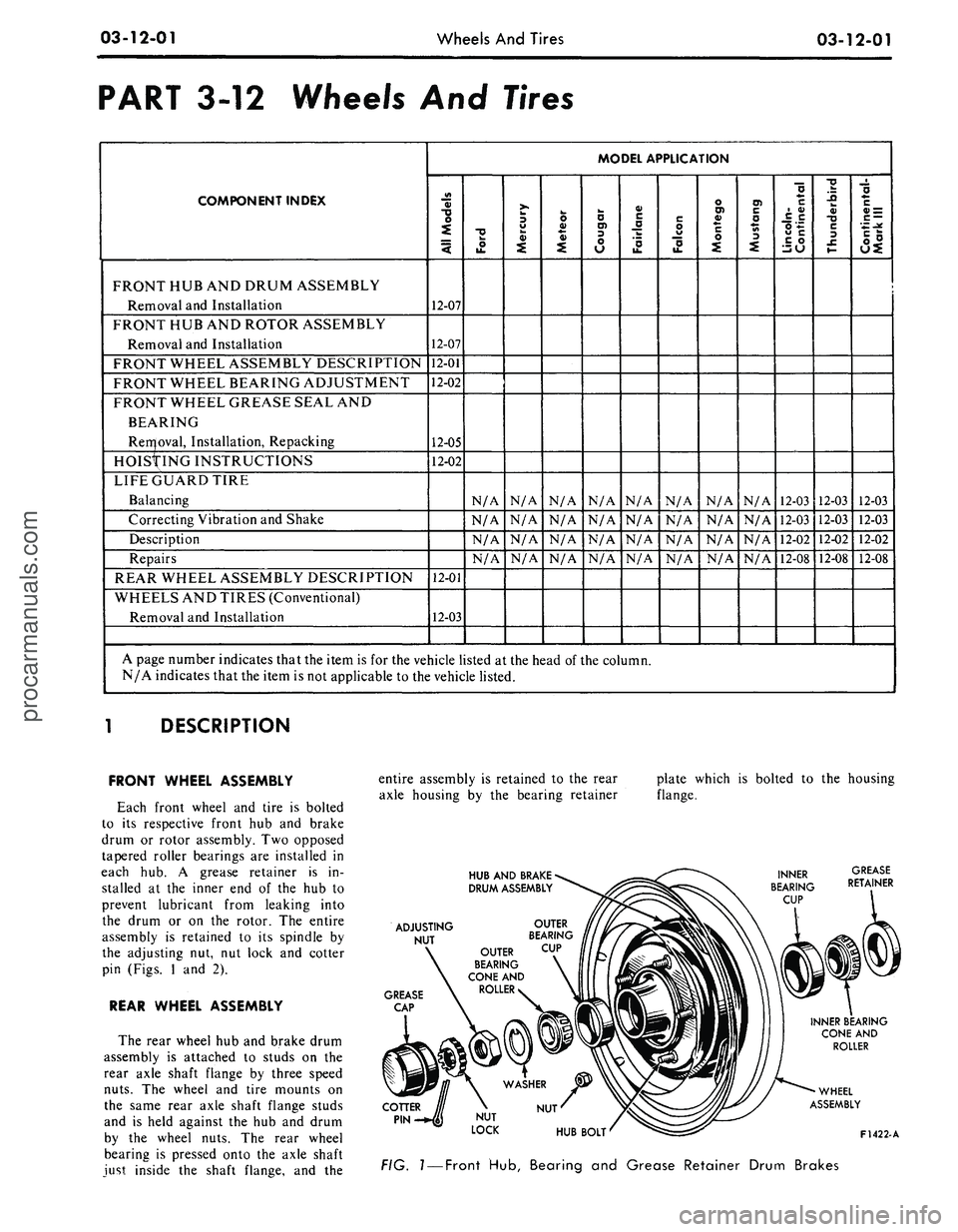
DESCRIPTION
FRONT WHEEL ASSEMBLY
Each front wheel
and
tire
is
bolted
to
its
respective front
hub and
brake
drum
or
rotor assembly.
Two
opposed
tapered roller bearings
are
installed
in
each
hub. A
grease retainer
is in-
stalled
at the
inner
end of the hub to
prevent lubricant from leaking into
the drum
or on the
rotor.
The
entire
assembly
is
retained
to its
spindle
by
the adjusting
nut, nut
lock
and
cotter
pin (Figs.
1 and 2).
REAR WHEEL ASSEMBLY
The rear wheel
hub and
brake drum
assembly
is
attached
to
studs
on the
rear axle shaft flange
by
three speed
nuts.
The
wheel
and
tire mounts
on
the same rear axle shaft flange studs
and
is
held against
the hub and
drum
by
the
wheel nuts.
The
rear wheel
bearing
is
pressed onto
the
axle shaft
just inside
the
shaft flange,
and the
entire assembly
is
retained
to the
rear
axle housing
by the
bearing retainer
HUB
AND
BRAKE
DRUM
ASSEMBLY
plate which
is
bolted
to the
housing
flange.
ADJUSTING
NUT
GREASE
CAP
OUTER
BEARING
OUTER
CUP
BEARING
CONE
AND
ROLLER
NUT
INNER BEARING
CONE
AND
ROLLER
WHEEL
ASSEMBLY
HUB
BOLT'
^£=3^
F1422-A
FIG.
1
—
Front
Hub,
Bearing
and
Grease Retainer Drum Brakes
procarmanuals.com
Page 173 of 413
03-12-02
Wheels
And
Tires
03-12-02
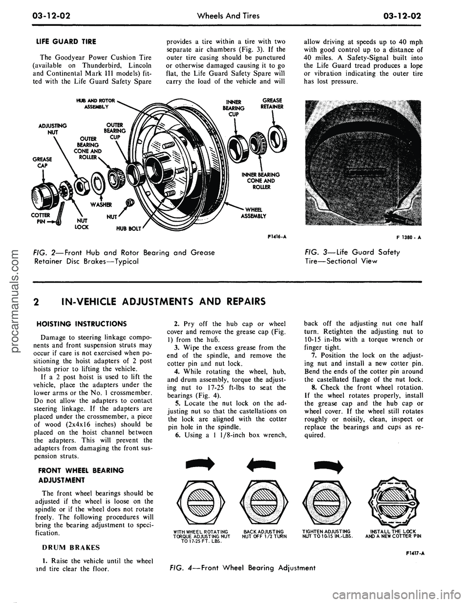
LIFE GUARD TIRE
The Goodyear Power Cushion Tire
(available
on
Thunderbird, Lincoln
and Continental Mark
III
models)
fit-
ted with
the
Life Guard Safety Spare
provides
a
tire within
a
tire with
two
separate
air
chambers
(Fig.
3). If the
outer tire casing should
be
punctured
or otherwise damaged causing
it to go
flat,
the
Life Guard Safety Spare will
carry
the
load
of the
vehicle
and
will
allow driving
at
speeds
up to 40 mph
with good control
up to a
distance
of
40 miles.
A
Safety-Signal built into
the Life Guard tread produces
a
lope
or vibration indicating
the
outer tire
has lost pressure.
HUB AND ROTOR
ASSEMBLY
INNER
BEARING
CUP
GREASE
RETAINER
ADJUSTING
NUT
OUTER
BEARING
CONE
AND
ROLLER
INNER BEARING
CONE
AND
ROLLER
WHEEL
ASSEMBLY
F1416-A
F- 1380 •
A
FIG. 2—Front
Hub and
Rotor Bearing
and
Grease
Retainer Disc Brakes—Typical
FIG. 3—Life Guard Safety
Tire—Sectional View
IN-VEHICLE ADJUSTMENTS AND REPAIRS
HOISTING INSTRUCTIONS
Damage
to
steering linkage compo-
nents
and
front suspension struts
may
occur
if
care
is
not
exercised when
po-
sitioning
the
hoist adapters
of 2
post
hoists prior
to
lifting
the
vehicle.
If
a 2
post hoist
is
used
to
lift
the
vehicle, place
the
adapters under
the
lower arms
or
the No. 1
crossmember.
Do
not
allow
the
adapters
to
contact
steering linkage.
If the
adapters
are
placed under
the
crossmember,
a
piece
of wood (2x4x16 inches) should
be
placed
on the
hoist channel between
the adapters. This will prevent
the
adapters from damaging
the
front
sus-
pension struts.
FRONT WHEEL BEARING
ADJUSTMENT
The front wheel bearings should
be
adjusted
if the
wheel
is
loose
on the
spindle
or if the
wheel does
not
rotate
freely.
The
following procedures will
bring
the
bearing adjustment
to
speci-
fication.
DRUM BRAKES
1.
Raise
the
vehicle until
the
wheel
and tire clear
the
floor.
2.
Pry off the hub cap or
wheel
cover
and
remove
the
grease
cap (Fig.
1) from
the hu6.
3.
Wipe
the
excess grease from
the
end
of the
spindle,
and
remove
the
cotter
pin and nut
lock.
4.
While rotating
the
wheel,
hub,
and drum assembly, torque
the
adjust-
ing
nut to 17-25
ft-lbs
to
seat
the
bearings
(Fig.
4).
5.
Locate
the nut
lock
on the ad-
justing
nut so
that
the
castellations
on
the lock
are
aligned with
the
cotter
pin hole
in the
spindle.
6. Using
a 1
1/8-inch
box
wrench,
WITH WHEEL ROTATING
TORQUE ADJUSTING
NUT
TO 17-25 FT. LBS.
BACK ADJUSTING
NUT
OFF
1/2
TURN
back
off the
adjusting
nut one
half
turn. Retighten
the
adjusting
nut to
10-15 in-lbs with
a
torque wrench
or
finger tight.
7.
Position
the
lock
on the
adjust-
ing
nut and
install
a new
cotter
pin.
Bend
the
ends
of
the
cotter
pin
around
the castellated flange
of the nut
lock.
8. Check
the
front wheel rotation.
If
the
wheel rotates properly, install
the grease
cap and the hub cap or
wheel cover.
If the
wheel still rotates
roughly
or
noisily, clean, inspect
or
replace
the
bearings
and
cups
as re-
quired.
TIGHTEN ADJUSTING
NUT
TO
10-15 IN.-LBS.
INSTALL THE LOCK
AND
A
NEW COTTER
PIN
F1417-A
FIG. 4— Front Wheel Bearing Adjustmentprocarmanuals.com
Page 174 of 413
03-12-03
Wheels And Tires
03-12-03
DISC BRAKES
1.
Raise the vehicle until the wheel
and tire clear the floor.
2.
Pry off the wheel cover and re-
move the grease cap (Fig. 2) from the
hub.
3.
Wipe the excess grease from the
end of the spindle, and remove the ad-
justing nut cotter pin and nut lock.
4.
Loosen the bearing adjusting nut
three turns. Then, rock the wheel,
hub,
and rotor assembly in and out
several times to push the shoe and lin-
ings away from the rotor.
5.
While rotating the wheel, hub,
and rotor assembly, torque the adjust-
ing nut to 17-25 ft-lbs to seat the
bearings (Fig. 4).
6. Back the adjusting nut off one
half turn. Then, retighten the adjust-
ing nut to 10-15 in-lbs with a torque
wrench or finger tight.
7.
Locate the nut lock on the ad-
justing nut so that the castellations on
the lock are aligned with the cotter
pin hole in the spindle.
8. Install a new cotter pin, and
bend the ends of the cotter pin around
the castellated flange of the nut lock.
9. Check the front wheel rotation.
If the wheel rotates properly, install
the grease cap and the hub cap or
wheel cover. If the wheel still rotates
roughly or noisily, clean or replace the
bearings and cups as required.
10.
Before driving the vehicle,
pump the brake pedal several times to
obtain normal brake lining to rotor
clearance and restore normal brake
pedal travel.
BALANCING LIFE
GUARD TIRE
Tires fitted with the Life Guard
Safety Spare are balanced in the same
manner as conventional tires. If an ex-
cessive out of balance condition exists
the following procedure can be used to
correct the condition:
1.
Remove the core housing and de-
flate both air chambers.
2.
Install the core housing.
3.
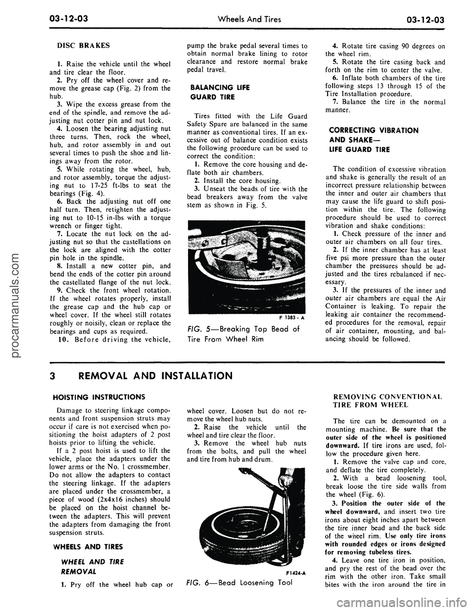
Unseat the beads of tire with the
bead breakers away from the valve
stem as shown in Fig. 5.
F 1383
FIG. 5—Breaking Top Bead of
Tire From Wheel Rim
4.
Rotate tire casing 90 degrees on
the wheel rim.
5.
Rotate the tire casing back and
forth on the rim to center the valve.
6. Inflate both chambers of the tire
following steps 13 through 15 of the
Tire Installation procedure.
7.
Balance the tire in the normal
manner.
CORRECTING VIBRATION
AND SHAKE-
LIFE GUARD TIRE
The condition of excessive vibration
and shake is generally the result of an
incorrect pressure relationship between
the inner and outer air chambers that
may cause the life guard to shift posi-
tion within the tire. The following
procedure should be used to correct
vibration and shake conditions:
1.
Check pressure of the inner and
outer air chambers on all four tires.
2.
If the inner chamber has at least
five psi more pressure than the outer
chamber the pressures should be ad-
justed and the tires rebalanced if nec-
essary.
3.
If the pressures of the inner and
outer air chambers are equal the Air
Container is leaking. To repair the
leaking air container the recommend-
ed procedures for the removal, repair
of air container, mounting, and bal-
ancing should be followed.
REMOVAL AND INSTALLATION
HOISTING INSTRUCTIONS
Damage to steering linkage compo-
nents and front suspension struts may
occur if care is not exercised when po-
sitioning the hoist adapters of 2 post
hoists prior to lifting the vehicle.
If a 2 post hoist is used to lift the
vehicle, place the adapters under the
lower arms or the No. 1 crossmember.
Do not allow the adapters to contact
the steering linkage. If the adapters
are placed under the crossmember, a
piece of wood (2x4x16 inches) should
be placed on the hoist channel be-
tween the adapters. This will prevent
the adapters from damaging the front
suspension struts.
WHEELS AND TIRES
WHEEL AND TIRE
REMOVAL
1.
Pry off the wheel hub cap or
wheel cover. Loosen but do not re-
move the wheel hub nuts.
2.
Raise the vehicle until the
wheel and tire clear the floor.
3.
Remove the wheel hub nuts
from the bolts, and pull the wheel
and tire from hub and drum.
F1424-
A
FIG.
6—Bead
Loosening Tool
REMOVING CONVENTIONAL
TIRE FROM WHEEL
The tire can be demounted on a
mounting machine. Be sure that the
outer side of the wheel is positioned
downward. If tire irons are used, fol-
low the procedure given here.
1.
Remove the valve cap and core,
and deflate the tire completely.
2.
With a bead loosening tool,
break loose the tire side walls from
the wheel (Fig. 6).
3.
Position the outer side of the
wheel downward, and insert two tire
irons about eight inches apart between
the tire inner bead and the back side
of the wheel rim. Use only tire irons
with rounded edges or irons designed
for removing tubeless tires.
4.
Leave one tire iron in position,
and pry the rest of the bead over the
rim with the other iron. Take small
bites with the iron around the tire inprocarmanuals.com
Page 177 of 413
03-12-06
Wheels And Tires
03-12-06
Tool-T56P-1217-A
INNER CUP
INSTALLATION
OUTER CUP
INSTALLATION
F1464-A
FIG. ^.Installing Front Wheel
Drum Bearing Cups
LUBR
F1427. A
FIG. 75—Front Wheel Hub
Lubrication
10.
All old grease should be com-
pletely cleaned from the bearings and
surrounding surfaces before repacking
them with new grease (C1AZ-
19590-B). The new lithium base grease
is not compatible with sodium base
grease which may have been present
on the bearing surfaces. Pack the
bearing cone and roller assemblies
with wheel bearing grease. A bearing
packer is desirable for this operation.
If a packer is not available, work as
much lubricant as possible between
the rollers and cages. Lubricate the
cone surfaces with grease.
11.
Place the inner bearing cone
and roller assembly in the inner cup,
Apply a light film of grease to the
lip(s) of the grease retainer and install
the new grease retainer with the rev-
erse end of the tool shown in Fig. 6.
Be sure that the retainer is properly
seated.
12.
Adjust the brake shoes as out-
lined in Group 2.
13.
Install the wheel, hub, and
drum assembly on the wheel spindle.
Keep the hub centered on the spindle
to prevent damage to the grease re-
tainer or the spindle threads.
14.
Install the outer bearing cone
and roller assembly and the flat wash-
er on the spindle, then install the ad-
justing nut (Fig. 1).
15.
Adjust the wheel bearings as
outlined in Section 2, and install a
new cotter pin. Bend the ends of the
cotter pin around the castellations of
the nut lock to prevent interference
with the radio static collector in the
grease cap. Install the grease cap.
16.
Install the hub cap or wheel
cover.
DISC BRAKES
1.
Raise the vehicle until the wheel
and tire clear the floor.
2.
Remove the wheel cover or hub
cap from the wheel.
3.
Remove the wheel and tire from
the hub and rotor.
4.
Remove 2 bolts and washers that
attach the caliper to the spindle. Re-
move the caliper from the rotor and
wire it to the underbody to prevent
damage to the brake hose.
5.
Remove the grease cap from the
hub.
Remove the cotter pin, nut lock,
adjusting nut, and flat washer from
the spindle. Remove the outer bearing
cone and roller assembly (Fig. 2).
6. Pull the hub and rotor assembly
off the wheel spindle.
7.
Remove and discard the old
grease retainer and the inner bearing
cone and roller assembly from the
hub.
8. Clean the lubricant off the inner
and outer bearing cups with solvent
and inspect the cups for scratches,
pits,
excessive wear, and other dam-
age.
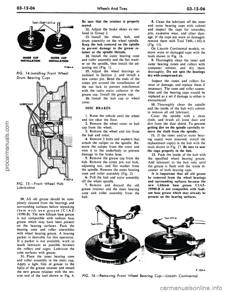
If the cups are worn or damaged,
remove them with Tool T69L-1102-A
(Fig. 13).
On Lincoln Continental models, re-
move worn or damaged cups with the
tools shown in Fig. 16.
9. Thoroughly clean the inner and
outer bearing cones and rollers with
computer solvent, and dry them
thoroughly. Do not spin the bearings
dry with compressed air.
Inspect the cones and rollers for
wear or damage, and replace them if
necessary. The cone and roller assem-
blies and the bearing cups should be
replaced as a set if damage to either is
encountered.
10.
Thoroughly clean the spindle
and the inside of the hub with solvent
to remove all old lubricant.
Cover the spindle with a clean
cloth, and brush all loose dust and
dirt from the dust shield. To prevent
getting dirt on the spindle carefully re-
move the cloth from the spindle.
11.
If the inner and/or outer bear-
ing cup(s) were removed, install the
replacement cup(s) in the hub with the
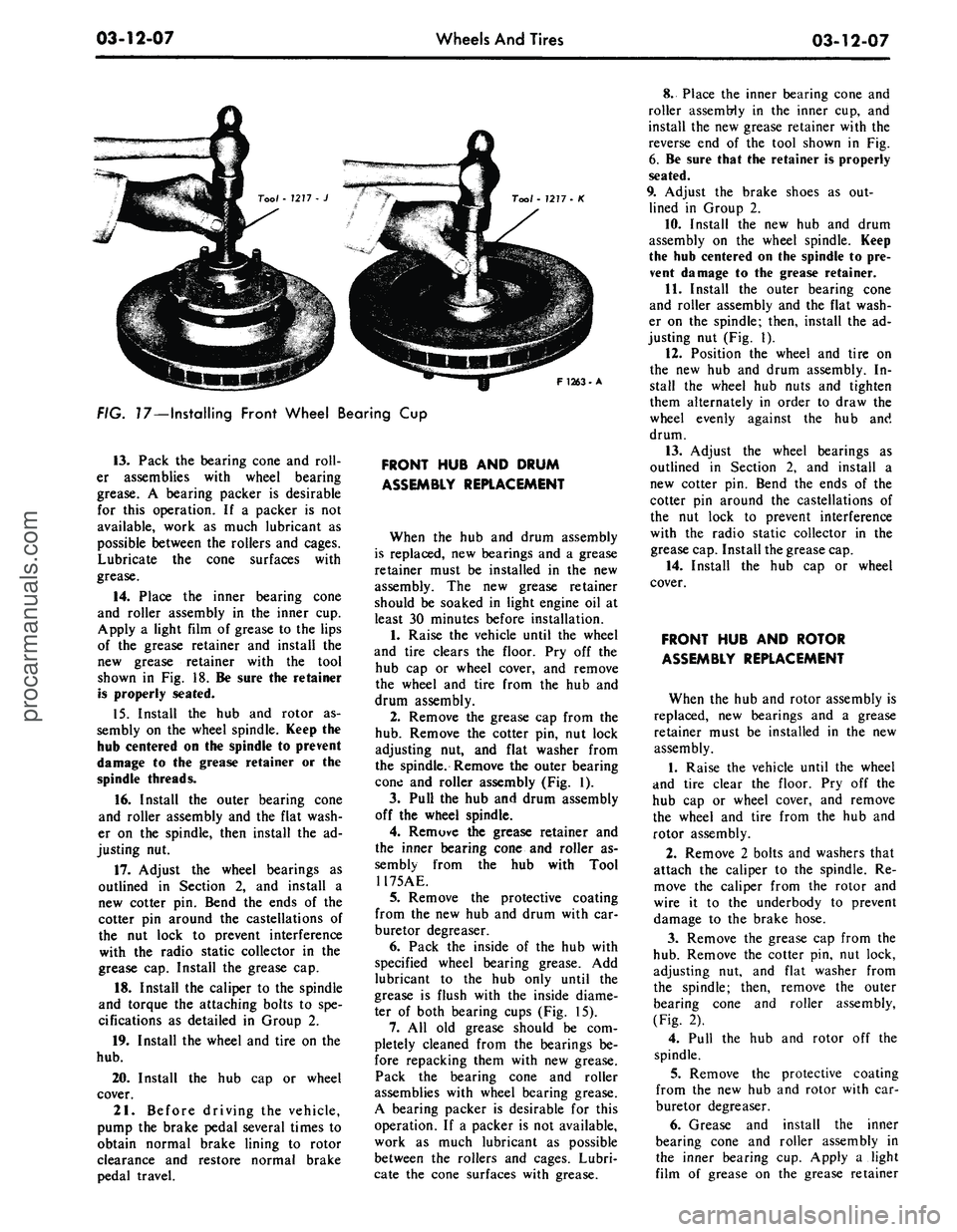
tools shown in Fig. 17. Be sure to seat
the cups properly in the hub.
12.
Pack the inside of the hub with
the specified wheel bearing grease.
Add lubricant to the hub only until
the grease is flush with the inside di-
ameter of both bearing cups.
It is important that all old grease
be removed from the wheel bearings
and surrounding surfaces because the
new Lithium base grease C1AZ-
19590-B is not compatible with Sodi-
um base grease which may already be
present on the bearing surfaces.
F 1502-A
FIG. 16—Removing Front Wheel Bearing Cup—Lincoln Continentalprocarmanuals.com
Page 178 of 413
03-12-07
Wheels And Tires
03-12-07
Tool - 7277- K
F 1263-A
FIG. 17—Installing Front Wheel Bearing Cup
13.
Pack the bearing cone and roll-
er assemblies with wheel bearing
grease. A bearing packer is desirable
for this operation. If a packer is not
available, work as much lubricant as
possible between the rollers and cages.
Lubricate the cone surfaces with
grease.
14.
Place the inner bearing cone
and roller assembly in the inner cup.
Apply a light film of grease to the lips
of the grease retainer and install the
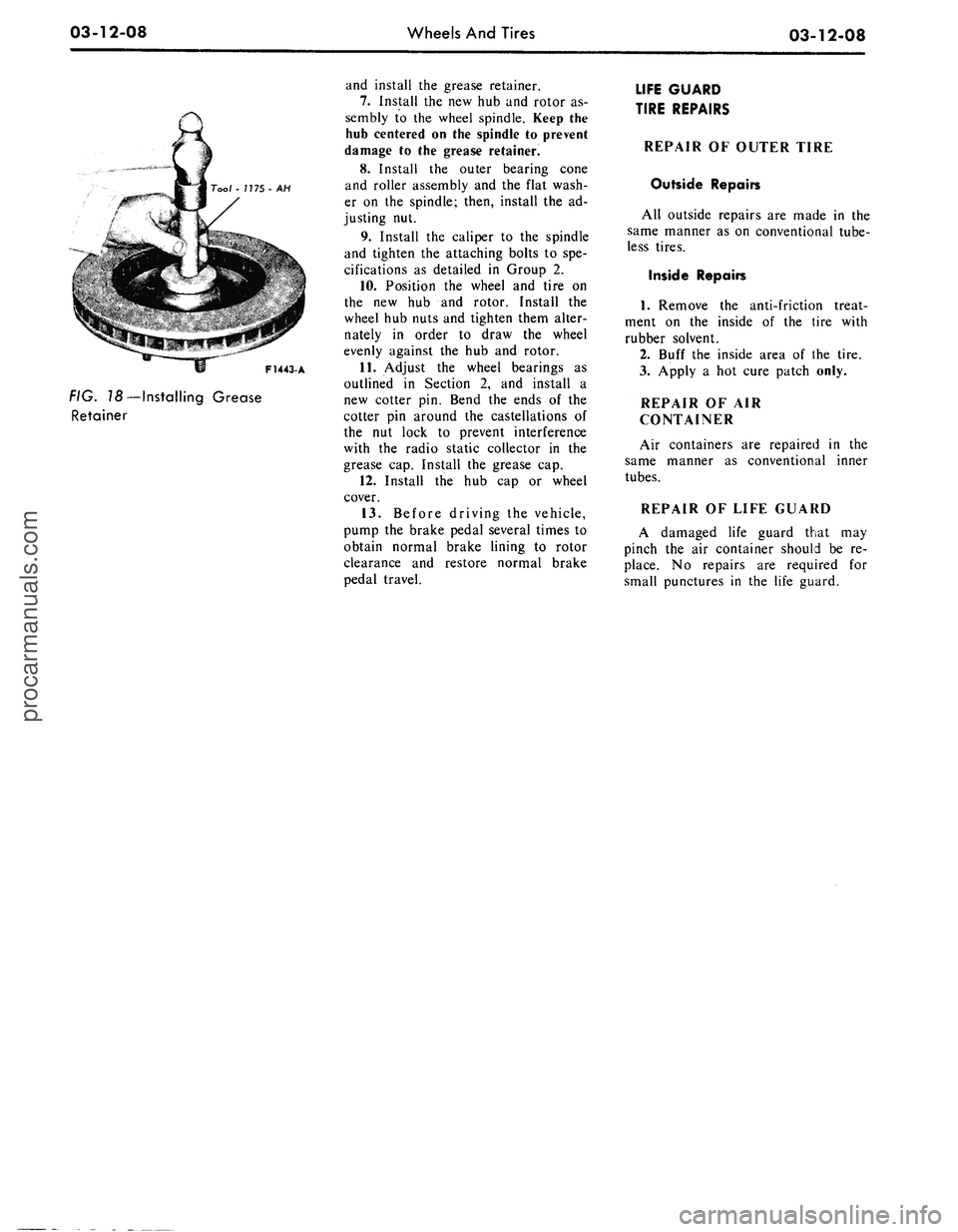
new grease retainer with the tool
shown in Fig. 18. Be sure the retainer
is properly seated.
15.
Install the hub and rotor as-
sembly on the wheel spindle. Keep the
hub centered on the spindle to prevent
damage to the grease retainer or the
spindle threads.
16.
Install the outer bearing cone
and roller assembly and the flat wash-
er on the spindle, then install the ad-
justing nut.
17.
Adjust the wheel bearings as
outlined in Section 2, and install a
new cotter pin. Bend the ends of the
cotter pin around the castellations of
the nut lock to prevent interference
with the radio static collector in the
grease cap. Install the grease cap.
18.
Install the caliper to the spindle
and torque the attaching bolts to spe-
cifications as detailed in Group 2.
19.
Install the wheel and tire on the
hub.
20.
Install the hub cap or wheel
cover.
21.
Before driving the vehicle,
pump the brake pedal several times to
obtain normal brake lining to rotor
clearance and restore normal brake
pedal travel.
FRONT HUB AND DRUM
ASSEMBLY REPLACEMENT
When the hub and drum assembly
is replaced, new bearings and a grease
retainer must be installed in the new
assembly. The new grease retainer
should be soaked in light engine oil at
least 30 minutes before installation.
1.
Raise the vehicle until the wheel
and tire clears the floor. Pry off the
hub cap or wheel cover, and remove
the wheel and tire from the hub and
drum assembly.
2.
Remove the grease cap from the
hub.
Remove the cotter pin, nut lock
adjusting nut, and flat washer from
the spindle. Remove the outer bearing
cone and roller assembly (Fig. 1).
3.
Pull the hub and drum assembly
off the wheel spindle.
4.
Remuve the grease retainer and
the inner bearing cone and roller as-
sembly from the hub with Tool
1175AE.
5.
Remove the protective coating
from the new hub and drum with car-
buretor degreaser.
6. Pack the inside of the hub with
specified wheel bearing grease. Add
lubricant to the hub only until the
grease is flush with the inside diame-
ter of both bearing cups (Fig. 15).
7.
All old grease should be com-
pletely cleaned from the bearings be-
fore repacking them with new grease.
Pack the bearing cone and roller
assemblies with wheel bearing grease.
A bearing packer is desirable for this
operation. If a packer is not available,
work as much lubricant as possible
between the rollers and cages. Lubri-
cate the cone surfaces with grease.
8. Place the inner bearing cone and
roller assembly in the inner cup, and
install the new grease retainer with the
reverse end of the tool shown in Fig.
6. Be sure that the retainer is properly
seated.
9. Adjust the brake shoes as out-
lined in Group 2.
10.
Install the new hub and drum
assembly on the wheel spindle. Keep
the hub centered on the spindle to pre-
vent damage to the grease retainer.
11.
Install the outer bearing cone
and roller assembly and the flat wash-
er on the spindle; then, install the ad-
justing nut (Fig. 1).
12.
Position the wheel and tire on
the new hub and drum assembly. In-
stall the wheel hub nuts and tighten
them alternately in order to draw the
wheel evenly against the hub and
drum.
13.
Adjust the wheel bearings as
outlined in Section 2, and install a
new cotter pin. Bend the ends of the
cotter pin around the castellations of
the nut lock to prevent interference
with the radio static collector in the
grease cap. Install the grease cap.
14.
Install the hub cap or wheel
cover.
FRONT HUB AND ROTOR
ASSEMBLY REPLACEMENT
When the hub and rotor assembly is
replaced, new bearings and a grease
retainer must be installed in the new
assembly.
1.
Raise the vehicle until the wheel
and tire clear the floor. Pry off the
hub cap or wheel cover, and remove
the wheel and tire from the hub and
rotor assembly.
2.
Remove 2 bolts and washers that
attach the caliper to the spindle. Re-
move the caliper from the rotor and
wire it to the underbody to prevent
damage to the brake hose.
3.
Remove the grease cap from the
hub.
Remove the cotter pin, nut lock,
adjusting nut, and flat washer from
the spindle; then, remove the outer
bearing cone and roller assembly,
(Fig. 2).
4.
Pull the hub and rotor off the
spindle.
5.
Remove the protective coating
from the new hub and rotor with car-
buretor degreaser.
6. Grease and install the inner
bearing cone and roller assembly in
the inner bearing cup. Apply a light
film of grease on the grease retainerprocarmanuals.com
Page 179 of 413
03-12-08
Wheels And Tires
03-12-08
Tool -
7
775 - AH
F1443-A
FIG.
18
— Installing Grease
Retainer
and install the grease retainer.
7.
Install the new hub and rotor as-
sembly to the wheel spindle. Keep the
hub centered on the spindle to prevent
damage to the grease retainer.
8. Install the outer bearing cone
and roller assembly and the flat wash-
er on the spindle; then, install the ad-
justing nut.
9. Install the caliper to the spindle
and tighten the attaching bolts to spe-
cifications as detailed in Group 2.
10.
Position the wheel and tire on
the new hub and rotor. Install the
wheel hub nuts and tighten them alter-
nately in order to draw the wheel
evenly against the hub and rotor.
11.
Adjust the wheel bearings as
outlined in Section 2, and install a
new cotter pin. Bend the ends of the
cotter pin around the castellations of
the nut lock to prevent interference
with the radio static collector in the
grease cap. Install the grease cap.
12.
Install the hub cap or wheel
cover.
13.
Before driving the vehicle,
pump the brake pedal several times to
obtain normal brake lining to rotor
clearance and restore normal brake
pedal travel.
LIFE GUARD
TIRE REPAIRS
REPAIR OF OUTER TIRE
Outside Repairs
All outside repairs are made in the
same manner as on conventional tube-
less tires.
Inside Repairs
1.
Remove the anti-friction treat-
ment on the inside of the tire with
rubber solvent.
2.
Buff the inside area of the tire.
3.
Apply a hot cure patch only.
REPAIR OF AIR
CONTAINER
Air containers are repaired in the
same manner as conventional inner
tubes.
REPAIR OF LIFE GUARD
A damaged life guard that may
pinch the air container should be re-
place. No repairs are required for
small punctures in the life guard.procarmanuals.com