Strut rod FORD MUSTANG 1969 Volume One Chassis
[x] Cancel search | Manufacturer: FORD, Model Year: 1969, Model line: MUSTANG, Model: FORD MUSTANG 1969Pages: 413, PDF Size: 75.81 MB
Page 87 of 413
03-02-11
Suspension
03-02-11
nuts to specification. Make sure that
the joint is completely filled with the
specified lubricant.
9. Guide the ball joint stud into the
spindle. Install the stud nut and tor-
que it to specification. Continue to
tighten the nut to line up the cotter
pin hole. Install the cotter pin.
10.
Install the wheel and tire. Tor-
que the wheel nuts to specification.
STABILIZER REPAIR
FORD, MERCURY,
METEOR, THUNDERBIRD,
CONTINENTAL MARK III
To replace the end bushings on each
stabilizer link, use the following pro-
cedure.
1.
Raise the vehicle on a hoist.
2.
Remove the nut, washer and in-
sulator from the lower end of the sta-
bilizer bar attaching bolt.
3.
Remove the bolt and the remain-
ing washers(3) insulators (3) and the
spacer.
4.
Assemble a flat washer and a
new insulator on the bolt.
5.
Insert the bolt through the stabi-
lizer bar then install a new insulator
and a flat washer on it.
6. Install the spacer, flat washer
and another new insulator on the bolt
(Fig. 1).
7.
Insert the bolt through the lower
arm and install a new insulator and a
flat washer. Install and torque the at-
taching nut to specification.
COUGAR, FAIRLANE,
FALCON, MONTEGO,
MUSTANG
1.
Raise the vehicle high enough to
provide working space, and place sup-
ports under both front wheels.
2.
Disconnect the stabilizer from
each link. Disconnect both stabilizer
attaching brackets, and remove the
stabilizer.
3.
Coat the necessary parts of the
stabilizer with RUGLYDE or a com-
parable lubricant, and slide new insu-
lators onto the stabilizer.
4.
Secure each end of the stabilizer
bar to the lower arm making sure that
the bolt head is at the top (Fig. 2) to
eliminate interference with the brake
hose.
5.
Remove the supports and lower
the vehicle.
FRONT SUSPENSION LOWER
ARM STRUT AND/OR
BUSHING
FORD, MERCURY,
METEOR, THUNDERBIRD,
CONTINENTAL MARK III
1.
Remove the cotter pin from the
lower arm strut at the frame front
crossmember and remove the nut,
washer, and bushing from the strut.
2.
Remove nuts, washers, and bolts
attaching the strut and rubber bumper
to the lower arm (Fig. 1).
3.
Pull the strut from the frame
crossmember.
4.
Remove the crossmember rear
side bushing and washer from the
strut.
5.
Place the crossmember rear side
washer and bushing on the strut and
position the strut to the frame and
lower arm.
6. Position the rubber bumper on
the strut and install the bolts, washer,
and nuts attaching the strut to the
lower arm. Torque the nuts and bolts
to specification.
7.
Install the bushing, washer, and
nut on the strut at the front cross-
member. Tighten the nut and install
the cotter pin.
8. Check caster, camber, and toe-in
and adjust if necessary.
LOWER ARM STRUT AND/OR
BUSHING REPLACEMENT
COUGAR, FAIRLANE,
FALCON, MONTEGO,
MUSTANG
1.
Position the support as shown in
Figs.
8 and 9 under the upper arm.
2.
Raise the vehicle, position safety
stands, and remove the wheel and tire.
3.
Remove the cotter pin, castelated
nut and the adjustment nut from the
front of the strut.
4.
With two pry bars approximately
18 inches long, one at each side and at
the rear of the front washer, pry it
forward to separate the inner sleeve
from the outer sleeve. Remove the
front insulator from the strut (Fig.
26).
5.
Install the new rear washer
(large ID), outer sleeve and insulator
bushing on the forward end of the
strut rod.
6. Position the strut into the
crossmember and to the lower suspen-
sion arm. Install the strut-to-arm at-
taching bolts and nuts, and torque
them to specification.
7.
Install the forward insulator
washer (small ID), inner sleeve and
adjustment nut on the forward end of
the strut. The inner sleeve need not be
crimped to the outer sleeve.
8. Install the wheel and tire, re-
move the safety stands and lower the
vehicle. Remove the tool supporting
the upper arm.
9. Adjust the caster and camber to
specification.
10.
Install the castellated nut and
cotter pin.
DRIVE SHAFT PINION
ANGLE ADJUSTMENT
FORD, MERCURY,
METEOR, THUNDERBIRD,
CONTINENTAL MARK III
The pinion-drive shaft working
angle must be checked and adjusted to
ADJUSTING
SCREW
F1432- A
F1503-A
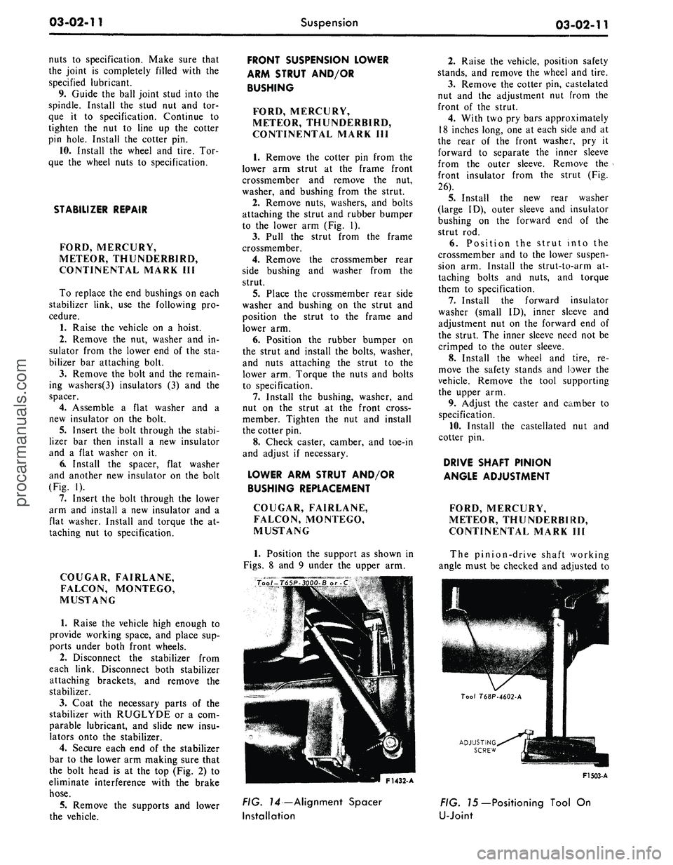
FIG. 14—Alignment Spacer
Installation
FIG. 75—Positioning Tool On
U-Jointprocarmanuals.com
Page 173 of 413
03-12-02
Wheels
And
Tires
03-12-02
LIFE GUARD TIRE
The Goodyear Power Cushion Tire
(available
on
Thunderbird, Lincoln
and Continental Mark
III
models)
fit-
ted with
the
Life Guard Safety Spare
provides
a
tire within
a
tire with
two
separate
air
chambers
(Fig.
3). If the
outer tire casing should
be
punctured
or otherwise damaged causing
it to go
flat,
the
Life Guard Safety Spare will
carry
the
load
of the
vehicle
and
will
allow driving
at
speeds
up to 40 mph
with good control
up to a
distance
of
40 miles.
A
Safety-Signal built into
the Life Guard tread produces
a
lope
or vibration indicating
the
outer tire
has lost pressure.
HUB AND ROTOR
ASSEMBLY
INNER
BEARING
CUP
GREASE
RETAINER
ADJUSTING
NUT
OUTER
BEARING
CONE
AND
ROLLER
INNER BEARING
CONE
AND
ROLLER
WHEEL
ASSEMBLY
F1416-A
F- 1380 •
A
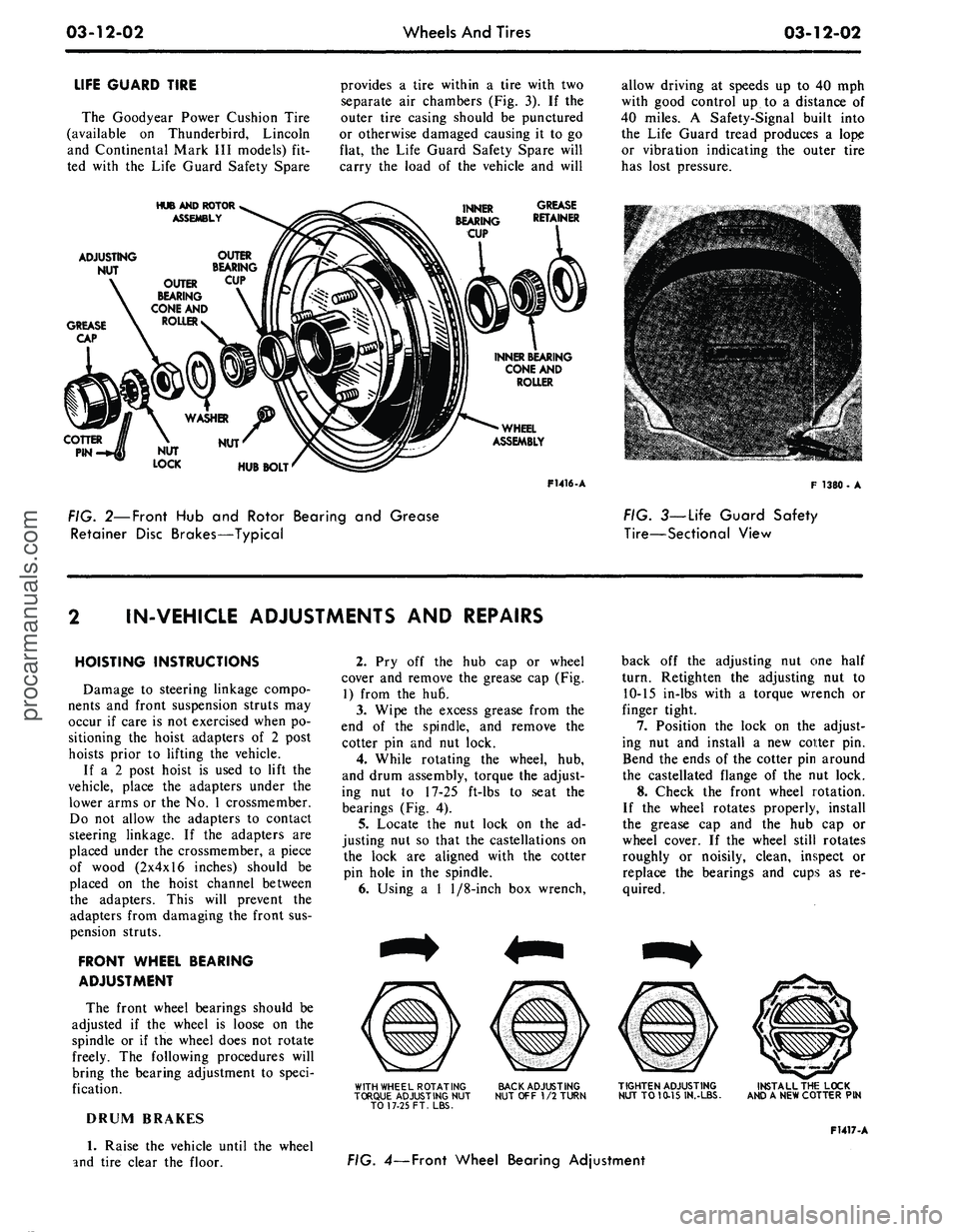
FIG. 2—Front
Hub and
Rotor Bearing
and
Grease
Retainer Disc Brakes—Typical
FIG. 3—Life Guard Safety
Tire—Sectional View
IN-VEHICLE ADJUSTMENTS AND REPAIRS
HOISTING INSTRUCTIONS
Damage
to
steering linkage compo-
nents
and
front suspension struts
may
occur
if
care
is
not
exercised when
po-
sitioning
the
hoist adapters
of 2
post
hoists prior
to
lifting
the
vehicle.
If
a 2
post hoist
is
used
to
lift
the
vehicle, place
the
adapters under
the
lower arms
or
the No. 1
crossmember.
Do
not
allow
the
adapters
to
contact
steering linkage.
If the
adapters
are
placed under
the
crossmember,
a
piece
of wood (2x4x16 inches) should
be
placed
on the
hoist channel between
the adapters. This will prevent
the
adapters from damaging
the
front
sus-
pension struts.
FRONT WHEEL BEARING
ADJUSTMENT
The front wheel bearings should
be
adjusted
if the
wheel
is
loose
on the
spindle
or if the
wheel does
not
rotate
freely.
The
following procedures will
bring
the
bearing adjustment
to
speci-
fication.
DRUM BRAKES
1.
Raise
the
vehicle until
the
wheel
and tire clear
the
floor.
2.
Pry off the hub cap or
wheel
cover
and
remove
the
grease
cap (Fig.
1) from
the hu6.
3.
Wipe
the
excess grease from
the
end
of the
spindle,
and
remove
the
cotter
pin and nut
lock.
4.
While rotating
the
wheel,
hub,
and drum assembly, torque
the
adjust-
ing
nut to 17-25
ft-lbs
to
seat
the
bearings
(Fig.
4).
5.
Locate
the nut
lock
on the ad-
justing
nut so
that
the
castellations
on
the lock
are
aligned with
the
cotter
pin hole
in the
spindle.
6. Using
a 1
1/8-inch
box
wrench,
WITH WHEEL ROTATING
TORQUE ADJUSTING
NUT
TO 17-25 FT. LBS.
BACK ADJUSTING
NUT
OFF
1/2
TURN
back
off the
adjusting
nut one
half
turn. Retighten
the
adjusting
nut to
10-15 in-lbs with
a
torque wrench
or
finger tight.
7.
Position
the
lock
on the
adjust-
ing
nut and
install
a new
cotter
pin.
Bend
the
ends
of
the
cotter
pin
around
the castellated flange
of the nut
lock.
8. Check
the
front wheel rotation.
If
the
wheel rotates properly, install
the grease
cap and the hub cap or
wheel cover.
If the
wheel still rotates
roughly
or
noisily, clean, inspect
or
replace
the
bearings
and
cups
as re-
quired.
TIGHTEN ADJUSTING
NUT
TO
10-15 IN.-LBS.
INSTALL THE LOCK
AND
A
NEW COTTER
PIN
F1417-A
FIG. 4— Front Wheel Bearing Adjustmentprocarmanuals.com
Page 317 of 413
07-02-09
C4 Automatic Transmission
07-02-09
11.
Remove the handle from the se-
lector lever.
12.
Install the selector housing and
lever assembly as shown in Figure 8.
Torque the attaching bolts 4-6 ft-lbs.
13.
Connect the dial indicator light.
14.
Install the pointer back-up
shield on the housing and lever assem-
bly.
15.
Install the dial housing and
tighten the attaching screws.
16.
Install the selector lever handle
and tighten the attaching screw.
17.
Position the selector lever in the
D position.
18.
Raise the vehicle. Install the
transmission manual lever rod to the
selector lever. Adjust the manual link-
age.
19.
Lower the vehicle and check the
transmission operation in each selo:c-
tor lever detent position.
BAND ADJUSTMENT
INTERMEDIATE BAND
1.
Clean all the dirt from the band
adjusting screw area. Remove and dis-
card the locknut.
2.
Install a new locknut on the ad-
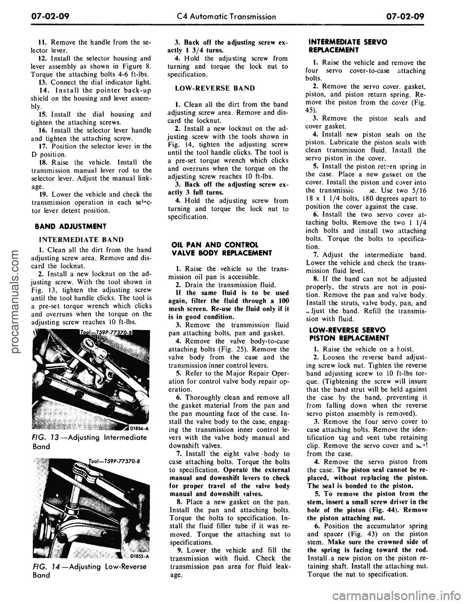
justing screw. With the tool shown in
Fig. 13, tighten the adjusting screw
until the tool handle clicks. The tool is
a pre-set torque wrench which clicks
and overruns when the torque on the
adjusting screw reaches 10 ft-lbs.
I D1854-A
FIG. 13—Adjusting Intermediate
Band
Tool-T59P-77370-B
D1855-A
FIG. 14—Adjusting Low-Reverse
Band
3.
Back off the adjusting screw ex-
actly 1 3/4 turns.
4.
Hold the adjusting screw from
turning and torque the lock nut to
specification.
LOW-REVERSE BAND
1.
Clean all the dirt from the band
adjusting screw area. Remove and dis-
card the locknut.
2.
Install a new locknut on the ad-
justing screw with the tools shown in
Fig. 14, tighten the adjusting screw
until the tool handle clicks. The tool is
a pre-set torque wrench which clicks
and overruns when the torque on the
adjusting screw reaches 10 ft-lbs.
3.
Back off the adjusting screw ex-
actly 3 full turns.
4.
Hold the adjusting screw from
turning and torque the lock nut to
specification.
OIL PAN AND CONTROL
VALVE BODY REPLACEMENT
1.
Raise the vehicle so the trans-
mission oil pan is accessible.
2.
Drain the transmission fluid.
If the same fluid is to be used
again, filter the fluid through a 100
mesh screen. Re-use the fluid only if it
is in good condition.
3.
Remove the transmission fluid
pan attaching bolts, pan and gasket.
4.
Remove the valve body-to-case
attaching bolts (Fig. 25). Remove the
valve body from the case and the
transmission inner control levers.
5.
Refer to the Major Repair Oper-
ation for control valve body repair op-
eration.
6. Thoroughly clean and remove all
the gasket material from the pan and
the pan mounting face of the case. In-
stall the valve body to the case, engag-
ing the transmission inner control le-
vers with the valve body manual and
downshift valves.
7.
Install the eight valve body to
case attaching bolts. Torque the bolts
to specification. Operate the external
manual and downshift levers to check
for proper travel of the valve body
manual and downshift valves.
8. Place a new gasket on the pan.
Install the pan and attaching bolts.
Torque the bolts to specification. In-
stall the fluid filler tube if it was re-
moved. Torque the attaching nut to
specifications.
9. Lower the vehicle and fill the
transmission with fluid. Check the
transmission pan area for fluid leak-
age.
INTERMEDIATE SERVO
REPLACEMENT
1.
Raise the vehicle and remove the
four servo cover-to-case attaching
bolts.
2.
Remove the servo cover, gasket,
piston, and piston return spring. Re-
move the piston from the cover (Fig.
45).
3.
Remove the piston seals and
cover gasket.
4.
Install new piston seals on the
piston. Lubricate the piston seals with
clean transmission fluid. Install the
servo piston in the cover.
5.
Install the piston retvrn spring in
the case. Place a new gasicet on the
cover. Install the piston and cover into
the transmissic se. Use two 5/16
18 x 1 1/4 bolts, 180 degrees apart to
position the cover against the case.
6. Install the two servo cover at-
taching bolts. Remove the two 1 1/4
inch bolts and install two attaching
bolts.
Torque the bolts to specifica-
tion.
7.
Adjust the intermediate band.
Lower the vehicle and check the trans-
mission fluid level.
8. If the band can not be adjusted
properly, the struts are not in posi-
tion. Remove the pan and valve body.
Install the struts, valve body, pan, and
adjust the band. Refill the transmis-
sion with fluid.
LOW-REVERSE SERVO
PISTON REPLACEMENT
1.
Raise the vehicle on a hoist.
2.
Loosen the reverse band adjust-
ing screw lock nut. Tighten the reverse
band adjusting screw to 10 ft-lbs tor-
que.
(Tightening the screw will insure
that the band strut will be held against
the case by the band, preventing it
from falling down when the reverse
servo piston assembly is removed).
3.
Remove the four servo cover to
case attaching bolts. Remove the iden-
tification tag and vent tube retaining
clip.
Remove the servo cover and s»»^
from the case.
4.
Remove the servo piston from
the case. The piston seal cannot be re-
placed, without replacing the piston.
The seal is bonded to the piston.
5. To remove the piston from the
stem, insert a small screw driver in the
hole of the piston (Fig. 44). Remove
the piston attaching nut.
6. Position the accumulator spring
and spacer (Fig. 43) on the piston
stem. Make sure the crowned side of
the spring is facing toward the rod.
Install.a new piston on the piston re-
taining shaft. Install the attaching nut.
Torque the nut to specification.procarmanuals.com
Page 320 of 413
07-02-12
C4 Automatic Transmission
07-02-12
MAJOR REPAIR OPERATIONS
Before removing
any of the sub-
assemblies, thoroughly clean
the out-
side
of the
transmission
to
prevent dirt
from entering
the
mechanical parts.
During
the
repair operations, refer
to
Part 7-1
for
common adjustments
and
repairs
or
cleaning
and
inspection
pro-
cedures.
During
the
transmission disassem-
bly
or
assembly operations,
ten
thrust
washers located between
the sub-
assemblies must
be
removed
and in-
stalled.
It is
important that each
thrust washer
be in the
correct posi-
tion during
the
assembly operation.
To properly locate
and
identify
the
thrust washers,
the
various positions
of
the
thrust washers
are
shown
in the
illustrations
and are
numbered
1
through
10. No. 1 is at the
first thrust
washer located
at the
front pump.
The
last thrust washer,
No. 10, is
located
at
the
parking pawl ring gear.
DISASSEMBLY
OF
TRANSMISSION
1.
Remove
the
converter from
the
transmission front pump
and
convert-
er housing.
2.
Remove
the
transmission vacuum
unit with
the
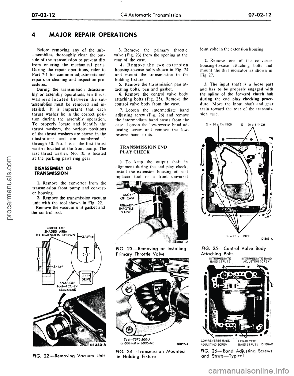
tool shown
in Fig. 22.
Remove
the
vacuum unit gasket and
the control
rod.
GRIND OFF
SHADED AREA
TO DIMENSION SHOWN L .
SNAP-ON
Tool-FCO-24
(Reworked)
D1380-A
FIG. 22—Removing Vacuum Unit
3.
Remove
the
primary throttle
valve (Fig.
23)
from
the
opening
at the
rear
of the
case.
4.
Remove
the two
extension
housing-to-case bolts shown
in Fig. 24
and mount
the
transmission
in the
holding fixture.
5.
Remove
the
transmission
pan at-
taching bolts,
pan and
gasket.
6. Remove
the
control valve body
attaching bolts (Fig.
25).
Remove
the
control valve body from
the
case.
7.
Loosen
the
intermediate band
adjusting screw
(Fig. 26) and
remove
the intermediate band struts from
the
case.
Loosen
the
low-reverse band
ad-
justing screw
and
remove
the low-
reverse band struts.
TRANSMISSION END
PLAY CHECK
1.
To
keep
the
output shaft
in
alignment during
the end
play check,
install
the
extension housing
oil
seal
replacer tool
or a
front universal
D1861-A
FIG. 23—Removing
or
Installing
Primary Throttle Valve
Tool-T57L-500-A
or 6005-M or 6005-MS
D1862-A
joint yoke in the extension housing.
2.
Remove
one of the
converter
housing-to-case attaching bolts
and
mount
the
dial indicator
as
shown
in
Fig. 27.
3.
The
input shaft
is a
loose part
and
has to be
properly engaged with
the spline
of the
forward clutch
hub
during
the end
play checking proce-
dure.
Move
the
input shaft
and
gear
train toward
the
rear
of the
transmis-
sion case.
V*
- 20 x
V/7 INCH
V*
- 20 x 1
INCH
V*
- 20 x 1
INCH
D1863-A
FIG. 25—Control Valve Body
Attaching Bolts
INTERMEDIATE
BAND STRUTS
INTERMEDIATE BAND
ADJUSTING SCREW
I
LOW-REVERSE BAND
ADJUSTING SCREW
LOW-REVERSE
BAND STRUTS
D
1384-B
FIG.
24—Transmission
Mounted
in Holding Fixture
FIG. 26—Band Adjusting Screws
and Struts—Typicalprocarmanuals.com
Page 324 of 413
07-02-16
C4 Automatic Transmission
07-02-16
COVER SEAL
STEM NUT
SERVO PISTON STEM
PISTON RETURN SPRING PISTON AND SEAL
(SEAL BONDED TO PISTON)
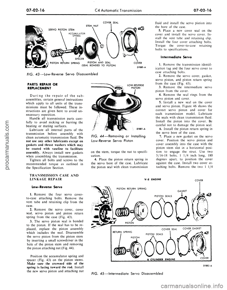
FIG. 43—Low-Reverse Servo Disassembled
PARTS REPAIR OR
REPLACEMENT
During the repair of the sub-
assemblies, certain general instructions
which apply to all units of the trans-
missions must be followed. These in-
structions are given here to avoid un-
necessary repetition.
Handle all transmission parts care-
fully to avoid nicking or burring the
bearing or mating surfaces.
Lubricate all internal parts of the
transmission before assembly with
clean automatic transmission fluid. Do
not use any other lubricants except on
gaskets and thrust washers which may
be coated with vaseline to facilitate
assembly. Always install new gaskets
when assembling the transmission.
Tighten all bolts and screws to the
recommended torque as outlined in
the Specification Section.
TRANSMISSION CASE AND
LINKAGE REPAIR
Low-Reverse Servo
1.
Remove the four servo cover-
to-case attaching bolts. Remove the
vent tube and retaining clip from the
case.
2.
Remove the servo cover, cover
seal, servo piston and piston return
spring from the case (Fig. 43).
3.
The servo piston seal is bonded
to the piston. If the seal has to be re-
placed, replace the piston assembly
which includes the seal. Disassemble
the servo piston from the piston stem
by inserting a small screwdriver in the
hole of the piston stem and removing
the piston attaching nut (Fig. 44).
Position the accumulator spring and
spacer (Fig. 43) on the piston stems.
Make sure the crowned side of the
spring is facing toward the rod. Install
the new servo piston and attaching nut
COVER
D1880-A
LOW-REVERSE
PISTON
D1881-A
FIG. 44—Removing or Installing
Low-Reverse Servo Piston
on the stem, torque the nut to specifi-
cation.
4.
Place the piston return spring in
the servo bore of the case. Lubricate
the piston seal with clean transmission
fluid and install the servo pistion into
the bore of the case.
5.
Place a new cover seal on the
cover and install the servo cover. In-
stall the vent tube and retaining clip.
Install the four cover attaching bolts.
Torque the cover-to-case retaining
bolts to specifications.
Intermediate Servo
1.
Remove the transmission
identif-
ication tag and the four servo cover to
case attaching bolts.
2.
Remove the servo cover, gasket,
servo piston, and piston return spring
from the case (Fig. 45).
3.
Remove the intermediate servo
piston from the cover.
4.
Remove the seal rings from the
servo piston and cover.
5.
Install a new seal on the cover
and servo piston. Figure 46 shows the
correct servo piston and cover for
each transmission model. Lubricate
the seals with clean transmission fluid.
Install the piston into the cover. Be
careful not to damage the piston seal.
6. Install the piston return spring in
the servo bore of the case.
7.
Place a new gasket on the servo
cover. Position the servo piston and
cover assembly into the case with the
piston stem slot in a horizontal posi-
tion to engage the strut. Use two
5/16-18 bolts, 1 1/4 inch long, 180
degrees apart, to position the cover
against the case. Install two cover at-
taching bolts. Remove the two 1 1/4
V-8 ENGINE
COVER
RETURN SPRING
PISTON
COVER SEAL COVER^ GASKET
PISTON SEALS
6 CYLINDER ENGINE
COVER
D1882-A
FIG. 45—Intermediate Servo Disassembledprocarmanuals.com
Page 352 of 413
07-03-12
FMX Transmission
07-03-12
11.
Move the control valve body
toward the center of the case until the
clearance is less than 0.050 inch, be-
tween the manual valve and the act-
uating pin on the manual detent lever.
12.
Torque the attaching bolts to
specification. Be sure that the rear
fluid filter retaining clip is installed
under the valve body bolt as shown in
Figure 17.
13.
Install the tubes to the pressure
regulator and the control valve body.
14.
Turn the manual valve one full
turn in each manual lever detent posi-
tion. If the manual valve binds against
the actuating pin in any detent posi-
tion, loosen the valve body attaching
bolts and move the body away from
the center of the case. Move the valve
body only enough to relieve the bind-
ing. Torque the attaching bolts and
recheck the manual valve for binding.
15.
Position the push rod in the
bore of the vacuum diaphragm unit.
Using the diaphragm unit as a guide,
insert the push rod into the threaded
opening of the case. Torque the dia-
phragm unit to specification. Connect
the vacuum hose.
16.
Torque the front servo attach-
ing bolts to specification.
17.
Adjust the front band. If the
unit is a model PHB-C, D, E, F, G or
H, adjust the rear band at this time.
18.
Install the fluid filter and the
filter retaining clip.
19.
Position a new fluid pan gasket
on the bottom of the transmission
case,
and install the pan. Torque the
pan screws to specification.
20.
Adjust the rear band on
PHB-A and PHD models.
21.
Fill the transmission with fluid.
If
the
fluid that
was
drained from
the
transmission
is to be
used
again,
filter
the fluid through
a
100-mesh screen
as
it
is
poured back into
the
transmis-
sion.
Re-use
the
fluid only
if it is in
good
condition.
22.
If the control valve body was
replaced, adjust the transmission con-
trol linkage.
PRESSURE REGULATOR
REPLACEMENT
1. Drain the fluid from the trans-
mission, and remove the pan and fluid
filter.
2.
Remove the small compensator
pressure tube and the large control
pressure tube from the control valve
body and the pressure regulator.
3.
Remove the pressure regulator
spring retainer, springs, and spacer.
Maintain pressure
on the
retainer
to
prevent
the
springs from flying
out.
4.
Remove the pressure regulator
attaching bolts and washers, and re-
move the regulator.
5.
Position the replacement regula-
tor body on the transmission case and
install the two attaching bolts. Torque
the bolts to specification.
6. Check the converter pressure and
control pressure valves to be sure the
valves operate freely in the bores.
7.
Install the valve springs, spacer,
and retainer.
8. Install the large control pressure
tube,
and the small compensator pres-
sure tube.
9. Install the fluid filter and the
pan, and fill the transmission to the
correct level with the specified fluid.
FRONT SERVO REPLACEMENT
1. Drain the fluid from the trans-
mission, and remove the pan and fluid
filter.
2.
Remove the vacuum diaphragm
unit.
3.
Loosen the three control valve
body attaching bolts.
4.
Remove the attaching bolts from
the front servo (Fig. 17), hold the
strut with the fingers, and remove the
servo.
5.
To install the front servo, posi-
tion the front band forward in the
case with the end of the band facing
downward. Make sure the front servo
anchor pin is in position in the case
web.
Align the large end of the servo
strut with the servo actuating lever,
and align the small end with the band
end.
6. Rotate the band, strut, and servo
to align the anchor end of the band
with the anchor in the case.
Push the servo body onto the con-
trol valve body tubes.
7.
Install the attaching bolts and
torque to specification.
8. Torque the control valve body
attaching bolts to specification.
Check the clearance between the
manual valve and manual lever actuat-
ing pin as given in Oil Pan and Con-
trol Valve Body Replacement.
9. Adjust the front band.
10.
Install the vacuum diaphragm
unit and rod.
11.
Install the fluid filter and pan,
and fill the transmission with fluid.
12.
Adjust the downshift and manu-
al linkage.
REAR SERVO REPLACEMENT
1. Drain the fluid from the trans-
mission, and remove the pan and fluid
filter.
2.
Remove the vacuum diaphragm
unit.
3.
Remove the control valve body
and the two front servo tubes.
4.
Remove the attaching bolts from
the rear servo, hold the actuating and
anchor struts with the fingers, and re-
move the servo. Remove the servo
dowel on PHB models.
5.
To install the rear servo, position
the servo anchor strut on the servo
band, and rotate the band to engage
the strut.
6. Hold the servo anchor strut in
position with the fingers, position the
actuating lever strut, and install the
servo. Insert the servo dowel on PHB
models.
7.
Install the servo attaching bolts,
and torque them to specification. The
longer bolt must
be
installed
in the
inner bolt
hole.
8.
Install the two front servo tubes
and the control valve body.
Check the clearance between the
manual valve and the manual lever
actuating pin as given above in Oil
Pan and Control Valve Body Replace-
ment.
9. Adjust the rear band.
10.
Install the fluid filter and pan,
and fill the transmission with fluid.
Too/~7?75-AB
7oo/-T50T-JOO-A
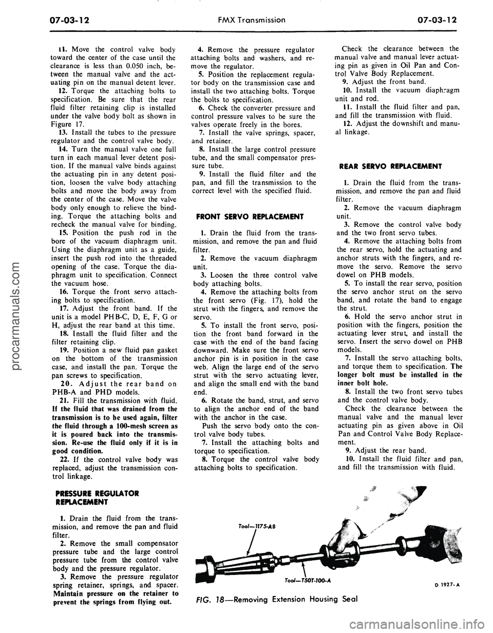
78—Removing Extension Housing Seal
D 1927-Aprocarmanuals.com
Page 380 of 413
07-04-11
C-6 Automatic Transmission
07-04-11
BAND ADJUSTMENT
INTERMEDIATE BAND
1.
Raise the vehicle on a hoist or
jack stands.
2.
Clean all the dirt from the band
adjusting screw area. Remove and dis-
card the lock nut.
3.
Install a new lock nut and tight-
en the adjusting screw to 10 ft-lbs tor-
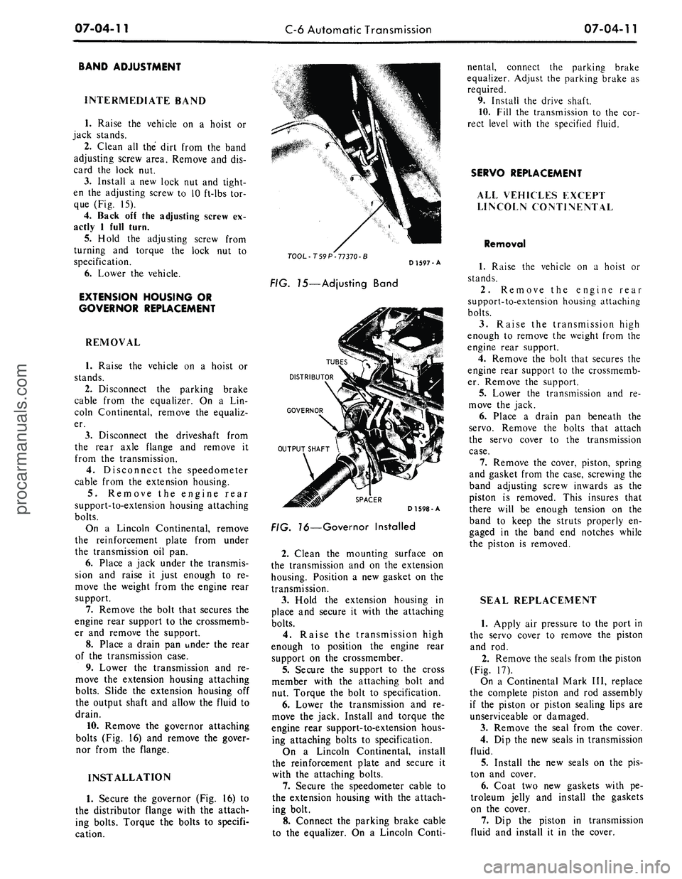
que (Fig. 15).
4.
Back off the adjusting screw ex-
actly 1 full turn.
5.
Hold the adjusting screw from
turning and torque the lock nut to
specification.
6. Lower the vehicle.
EXTENSION HOUSING OR
GOVERNOR REPLACEMENT
REMOVAL
1.
Raise the vehicle on a hoist or
stands.
2.
Disconnect the parking brake
cable from the equalizer. On a Lin-
coln Continental, remove the equaliz-
er.
3.
Disconnect the driveshaft from
the rear axle flange and remove it
from the transmission.
4.
Disconnect the speedometer
cable from the extension housing.
5.
Remove the engine rear
support-to-extension housing attaching
bolts.
On a Lincoln Continental, remove
the reinforcement plate from under
the transmission oil pan.
6. Place a jack under the transmis-
sion and raise it just enough to re-
move the weight from the engine rear
support.
7.
Remove the bolt that secures the
engine rear support to the crossmemb-
er and remove the support.
8. Place a drain pan under the rear
of the transmission case.
9. Lower the transmission and re-
move the extension housing attaching
bolts.
Slide the extension housing off
the output shaft and allow the fluid to
drain.
10.
Remove the governor attaching
bolts (Fig. 16) and remove the gover-
nor from the flange.
INSTALLATION
1.
Secure the governor (Fig. 16) to
the distributor flange with the attach-
ing bolts. Torque the bolts to specifi-
cation.
TOOL-T59 P-77370-B
FIG. 75—Adjusting Band
D 1597-A
TUBES
DISTRIBUTOR
GOVERNOR
SPACER
D1598-A
FIG. 76—Governor Installed
2.
Clean the mounting surface on
the transmission and on the extension
housing. Position a new gasket on the
transmission.
3.
Hold the extension housing in
place and secure it with the attaching
bolts.
4.
Raise the transmission high
enough to position the engine rear
support on the crossmember.
5.
Secure the support to the cross
member with the attaching bolt and
nut. Torque the bolt to specification.
6. Lower the transmission and re-
move the jack. Install and torque the
engine rear support-to-extension hous-
ing attaching bolts to specification.
On a Lincoln Continental, install
the reinforcement plate and secure it
with the attaching bolts.
7.
Secure the speedometer cable to
the extension housing with the attach-
ing bolt.
8. Connect the parking brake cable
to the equalizer. On a Lincoln Conti-
nental, connect the parking brake
equalizer. Adjust the parking brake as
required.
9. Install the drive shaft.
10.
Fill the transmission to the cor-
rect level with the specified fluid.
SERVO REPLACEMENT
ALL VEHICLES EXCEPT
LINCOLN CONTINENTAL
Removal
1.
Raise the vehicle on a hoist or
stands.
2.
Remove the engine rear
support-to-extension housing attaching
bolts.
3.
Raise the transmission high
enough to remove the weight from the
engine rear support.
4.
Remove the bolt that secures the
engine rear support to the crossmemb-
er. Remove the support.
5.
Lower the transmission and re-
move the jack.
6. Place a drain pan beneath the
servo.
Remove the bolts that attach
the servo cover to the transmission
case.
7.
Remove the cover, piston, spring
and gasket from the case, screwing the
band adjusting screw inwards as the
piston is removed. This insures that
there will be enough tension on the
band to keep the struts properly en-
gaged in the band end notches while
the piston is removed.
SEAL REPLACEMENT
1.
Apply air pressure to the port in
the servo cover to remove the piston
and rod.
2.
Remove the seals from the piston
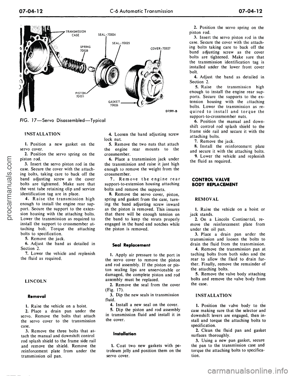
(Fig. 17).
On a Continental Mark III, replace
the complete piston and rod assembly
if the piston or piston sealing lips are
unserviceable or damaged.
3.
Remove the seal from the cover.
4.
Dip the new seals in transmission
fluid.
5.
Install the new seals on the pis-
ton and cover.
6. Coat two new gaskets with pe-
troleum jelly and install the gaskets
on the cover.
7.
Dip the piston in transmission
fluid and install it in the cover.procarmanuals.com
Page 381 of 413
07-04-12
C-6 Automatic Transmission
07-04-12
•TRANSMISSION
CASE SEAL-7D024
SEAL-7D025
COVER .7D027
D1599-B
FIG. 17—Servo Disassembled—Typical
INSTALLATION
1.
Position a new gasket on the
servo cover.
2.
Position the servo spring on the
piston rod.
3.
Insert the servo piston rod in the
case.
Secure the cover with the attach-
ing bolts, taking care to back off the
band adjusting screw as the cover
bolts are tightened. Make sure that
the vent tube retaining clip and service
identification tag are in place.
4.
Raise the transmission high
enough to install the engine rear sup-
port. Secure the support to the exten-
sion housing with the attaching bolts.
Lower the transmission as required to
install the support to crossmember at-
taching bolt. Torque the attaching
bolts to specification.
5.
Remove the jack.
6. Adjust the band as detailed in
Section 2.
7.
Lower the vehicle and replenish
the fluid as required.
LINCOLN
Removal
1.
Raise the vehicle on a hoist.
2.
Place a drain pan under the
servo.
Remove the bolts that attach
the servo cover to the transmission
case.
3.
Remove the three bolts that at-
tach the manual and downshift control
rod splash shield to the frame side rail
and remove the shield. Remove the
reinforcement plate from under the
transmission oil pan.
4.
Loosen the band adjusting screw
lock nut.
5.
Remove the two nuts that attach
the engine rear mounts to the
crossmember.
6. Place a transmission jack under
the transmission and raise it just high
enough to remove the weight from the
crossmember.
7.
Remove the engine rear
support-to-extension housing attaching
bolts and remove the supports.
8. Remove the servo cover, piston,
spring and gasket from the case, turn-
ing the band adjusting screw inward
as the piston is removed. This insures
that there will be enough tension on
the band to keep the struts properly
engaged in the band end notches while
the piston is removed.
Seal Replacement
1.
Apply air pressure to the port in
the servo cover to remove the piston
and rod assembly. If the piston or pis-
ton sealing lips are unserviceable or
damaged, the complete piston and rod
assembly must be replaced.
2.
Remove the seal from the cover
(Fig. 17).
3.
Dip the new seals in transmission
fluid.
4.
Install a new seal on the cover.
5.
Dip the piston and rod assembly
in transmission fluid and install it in
the cover.
Installation
1.
Coat two new gaskets with pe-
troleum jelly and position them on the
servo cover.
2.
Position the servo spring on the
piston rod.
3.
Insert the servo piston rod in the
case.
Secure the cover with the attach-
ing bolts taking care to back off the
band adjusting screw as the cover
bolts are tightened. Make sure that
the transmission identification tag is
installed utfider the lower front cover
bolt.
4.
Adjust the band as detailed in
Section 2.
5.
"Raise the transmission high
enough to install the engine rear sup-
ports.
Secure the supports to the ex-
tension housing with the attaching
bolts.
Lower the transmission as re-
quired to install and torque the
support-to-crossmember nuts.
6. Position the manual and down-
shift control rod splash shield to the
frame side rail and secure it with the
attaching bolts.
7.
Remove the jack.
8. Install the reinforcement plate
and secure it with the attaching bolts.
9. Lower the vehicle and replenish
the fluid as required.
CONTROL VALVE
BODY REPLACEMENT
REMOVAL
1.
Raise the vehicle on a hoist or
jack stands.
2.
On a Lincoln Continental, re-
move the reinforcement plate from
under the oil pan.
3.
Place a drain pan under the
transmission and loosen the bolts to
drain the fluid from the transmission.
4.
Remove the transmission pan at
taching bolts from both sides and the
rear to allow the fluid to drain fur-
ther. Finally, remove the remainder of
the attaching bolts.
5.
Remove the valve body attaching
bolts and remove the valve body from
the case.
INSTALLATION
1.
Position the valve body to the
case making sure that the selector and
downshift levers are engaged, then in-
stall and torque the attaching bolts to
specification.
2.
Clean the fluid pan and gasket
surfaces thoroughly.
3.
Using a new pan gasket, secure
the pan to the transmission case and
torque the attaching bolts to specifica-
tion.procarmanuals.com
Page 387 of 413
07-04-18
C-6 Automatic Transmission
07-04-18
16.
Position the manual and down-
shift control rod splash shield to the
frame side rail and secure it with the
attaching bolts.
17.
Connect the speedometer cable
to the extension housing.
18.
Connect the vacuum hose to the
vacuum diaphragm and secure with a
clamp.
19.
Connect the two oil cooler lines
to the fittings on the right side of the
case.
20.
Install the cooler lines under
the clip at the cylinder head.
21.
Position the reinforcement plate
and torque the attaching bolts.
22.
Install the equalizer and park-
ing brake cables. Install the equalizer
lever retracting spring.
23.
Install the drive shaft.
24.
Install a new seal on the filler
tube and install it in the transmission
case.
Secure the filler tube to the cyl-
inder head.
25.
Install the starting motor and
connect the cable.
26.
Install the idler arm bracket-
to-frame side rail.
27.
Lower the vehicle.
28.
Fill the transmission to the cor-
rect level with the specified fluid.
29.
Adjust the manual and throttle
linkage as required.
MAJOR REPAIR OPERATIONS
DISASSEMBLY OF
TRANSMISSION
1.
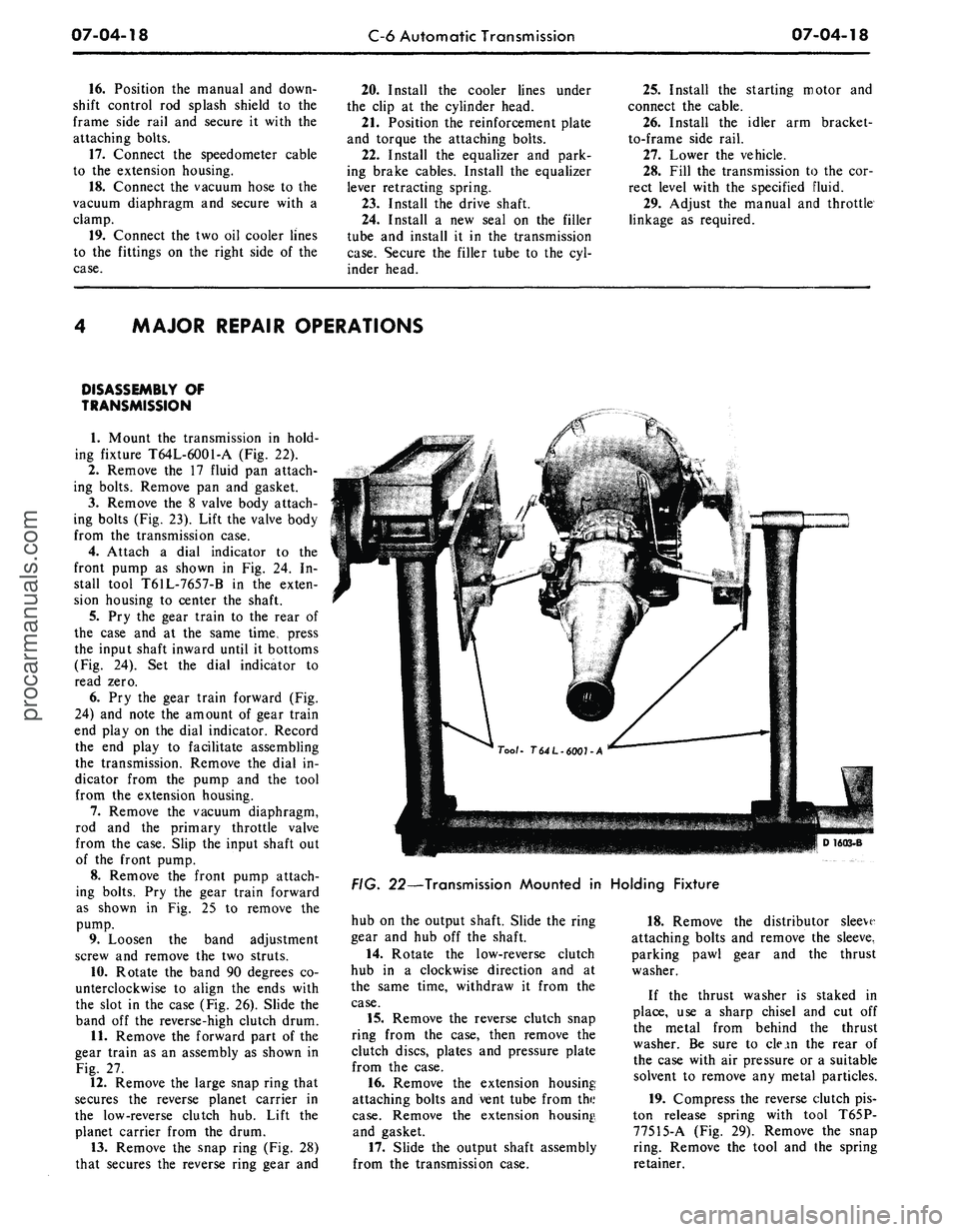
Mount the transmission in hold-
ing fixture T64L-6001-A (Fig. 22).
2.
Remove the 17 fluid pan attach-
ing bolts. Remove pan and gasket.
3.
Remove the 8 valve body attach-
ing bolts (Fig. 23). Lift the valve body
from the transmission case.
4.
Attach a dial indicator to the
front pump as shown in Fig. 24. In-
stall tool T61L-7657-B in the exten-
sion housing to center the shaft.
5.
Pry the gear train to the rear of
the case and at the same time, press
the input shaft inward until it bottoms
(Fig. 24). Set the dial indicator to
read zero.
6. Pry the gear train forward (Fig.
24) and note the amount of gear train
end play on the dial indicator. Record
the end play to facilitate assembling
the transmission. Remove the dial in-
dicator from the pump and the tool
from the extension housing.
7.
Remove the vacuum diaphragm,
rod and the primary throttle valve
from the case. Slip the input shaft out
of the front pump.
8. Remove the front pump attach-
ing bolts. Pry the gear train forward
as shown in Fig. 25 to remove the
pump.
9. Loosen the band adjustment
screw and remove the two struts.
10.
Rotate the band 90 degrees co-
unterclockwise to align the ends with
the slot in the case (Fig. 26). Slide the
band off the reverse-high clutch drum.
11.
Remove the forward part of the
gear train as an assembly as shown in
Fig. 27.
12.
Remove the large snap ring that
secures the reverse planet carrier in
the low-reverse clutch hub. Lift the
planet carrier from the drum.
13.
Remove the snap ring (Fig. 28)
that secures the reverse ring gear and
D16Q3-B
FIG. 22—Transmission Mounted in Holding Fixture
hub on the output shaft. Slide the ring
gear and hub off the shaft.
14.
Rotate the low-reverse clutch
hub in a clockwise direction and at
the same time, withdraw it from the
case.
15.
Remove the reverse clutch snap
ring from the case, then remove the
clutch discs, plates and pressure plate
from the case.
16.
Remove the extension housing
attaching bolts and vent tube from the
case.
Remove the extension housing,
and gasket.
17.
Slide the output shaft assembly
from the transmission case.
18.
Remove the distributor sleeve
attaching bolts and remove the sleeve,
parking pawl gear and the thrust
washer.
If the thrust washer is staked in
place, use a sharp chisel and cut off
the metal from behind the thrust
washer. Be sure to clean the rear of
the case with air pressure or a suitable
solvent to remove any metal particles.
19.
Compress the reverse clutch pis-
ton release spring with tool T65P-
77515-A (Fig. 29). Remove the snap
ring. Remove the tool and the spring
retainer.procarmanuals.com