washer fluid FORD MUSTANG 1969 Volume One Chassis
[x] Cancel search | Manufacturer: FORD, Model Year: 1969, Model line: MUSTANG, Model: FORD MUSTANG 1969Pages: 413, PDF Size: 75.81 MB
Page 34 of 413
BOLT-381877
TUBE-2267
BRACKET-2A448
TUBE-2268
VIEW IN CIRCLE X
TYPICAL 3 PLACES
TUBE ASSEMBLY-2B162
TUBE ASSEMBLY-2264
TUBE ASSEMBLY-2263
TUBE-2267
BEND CLIPS TO RETAIN
TUBES AT ASSEMBLY
5 PLACES
CHECK BRAKE HOSE CLEARANCE
TO ALL COMPONENTS IN METAL/METAL
JOUNCE AND METAL/METAL REBOUND
TUBE-2268
PROPORTIONING
VALVE ASSEMBLY
BRACKET-2B266
BOOSTER ASSEMBLY-2B195
PULLOUT WHILE BLEEDING
BRAKE SYSTEM-USE CARE
NOT TO BEND PIN
TUBE-2420
DIFFERENTIAL VALVE-C8VA
VIEW IN CIRCLE M
TUBE-2A280
TUBE-2A280
PRESSURE DIFFERENTIAL
VALVE ASSEMBLY-C8VA-2B328-C
TUBE ASSEMBLY-2264
BRACKET-2082 R.H.
-2AO56 L.H.
CLIP-97502
2 REQUIRED
357444-S 2 REQUIRED
TO CALIPER ASSEMBLY
HOSE-2B171 R.H.
-2B218 L.H.
VIEWN
HOSE-2A448
TUBE-2A280
VIEWP
SHIELD-2A337
VIEW IN CIRCLE S
TYPICAL 4 PLACES
TUBE-2A280
VIEWR
V1EWU
VIEWV
WASHER-2149 2 REQUIRED
TUBE-2B166 R.H.
-2B168 L.H.
STOP LAMPS MUST LIGHT WITH MAXIMUM FOOT
PEDAL EFFORT OF 4 POUNDS AND WITHOUT AUDIBLE
SOUND FROM THE SWITCH UNDER NORMAL OPERATION.
ALL BRAKE LINES, FITTINGS AND FLEXIBLE HOSES
MUST BE KEPT FREE OF FOREIGN MATERIAL BEFORE
AND DURING ASSEMBLY OPERATIONS.
ALL CONNECT
IONS,
TUBES,
MASTER CYLINDER AND
FITTINGS MUST BE FREE OF FLUID LEAKAGE.
H 1528-C
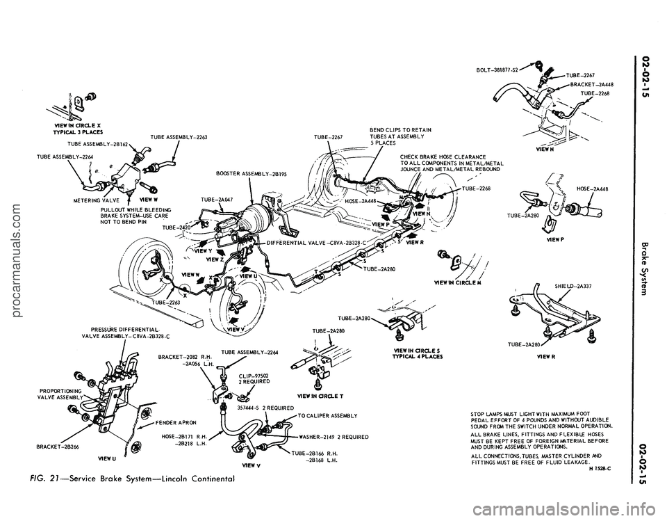
FIG. 21—Service Brake System—Lincoln Continentalprocarmanuals.com
Page 35 of 413
02-02-16
Brake System
02-02-16
fitting that connects the tube to the
cylinder. Do not pull the metal tube
away from the cylinder. Pulling the
tube out of the cylinder connection
will bend the metal tube and make in-
stallation difficult. The tube will sepa-
rate from the cylinder when the cylin-
der is removed from the backing
plate.
4.
On all except the front wheels on
Ford, Mercury, and Meteor models,
remove the wheel cylinder attaching
bolts and lock washers and remove the
cylinder. On the front wheel of Ford,
Mercury and Meteor models, remove
the nut and washer that attaches the
cylinder to the anchor pin. Remove
the cylinder from the anchor pin.
INSTALLATION
Wipe the end(s) of the hydraulic
line to remove any foreign matter be-
fore making connections.
1.
On all models except Ford, Mer-
cury and Meteor, to install a front
wheel cylinder, position the cylinder to
the backing plate. Install the two lock
washers and attaching bolts. Torque
them to specifications.
On Ford, Mercury and Meteor
models, to install a front wheel cylin-
der, position the cylinder on the an-
chor pin against the backing plate. In-
stall the washer and cylinder attaching
nut on the anchor pin, and torque it
to specification. Lock the washer re-
tainer securely.
2.
Install a new copper gasket over
the hose fitting. Thread the hose into
the cylinder and tighten it to specified
torque.
3.
Engage the opposite end of the
hose to the bracket on the frame. In-
stall the horseshoe-type retaining clip,
and connect the brake tube to the
hose with the tube fitting nut. Tighten
the nut to specification with tool
1112-144.
4.
To install a rear wheel cylinder,
place the rear wheel cylinder into po-
sition. Enter the tubing into the cylin-
der, and start the tube fitting nut into
the threads of the cylinder.
5.
Secure the cylinder to the back-
ing plate by installing the attaching
bolts and lock washers.
6. Tighten the tube fitting nut to
specification with tool 1112-144.
7.
Install the links in the ends of
the wheel cylinder, install the shoes
and adjuster assemblies, and adjust
the shoes as outlined in this section.
8. Adjust the brakes (Part 2-2, Sec-
tion 2). Install the brake drum and
wheel. Bleed the brakes and centralize
the differential valve as outlined in
Part 2-1, Section 2.
BRAKE BACKING PLATE
DRUM BRAKE
REMOVAL
1.
Remove the wheel and brake
drum. Disconnect the brake line from
the brake cylinder.
2.
Remove the brake shoe and ad-
juster assemblies and the wheel cylin-
der as outlined in this section. On the
rear wheels, disconnect the parking
brake lever from the cable.
3.
If the rear backing plate is being
replaced, remove the axle shaft from
the applicable rear axle as outlined in
Group 4, Part 4-2— Rear Axle, Sec-
tion 2, disengage parking brake cable
retainer from backing plate. Remove
the backing plate and gasket.
If the front backing plate is being
replaced, remove the bolts and nuts
that secure the backing plate to the
front wheel spindle and remove the
plate and gasket.
INSTALLATION
If a rear backing plate is to be re-
placed, position a new rear backing
plate and gasket on the attaching
bolts in the axle housing flange. Insert
parking brake cable into backing plate
and secure retaining fingers. Install
the rear axle shaft for applicable rear
axle.
Refer to Group 4, Part 4-2 —
Rear Axle, Section 2 for the proper
installation procedure.
1.
If the front brake backing plate
is to be replaced, position a new front
backing plate and gasket to the wheel
spindle and install the attaching bolts
and nuts.
2.
Install the wheel cylinder and
connect the brake line as outlined in
this section.
3.
Install the brake shoe and ad-
juster assemblies as outlined in this
section. On a rear brake, connect the
parking brake cable to the lever.
4.
Adjust the brake shoes (Section
2),
and install the brake drums and
wheels. Bleed the brake system and
centralize the differential valve as out-
lined in Part 2-1, Section 2.
DISC BRAKE CALIPER
ASSEMBLY
ALL MODELS EXCEPT
LINCOLN CONTINENTAL
Removal
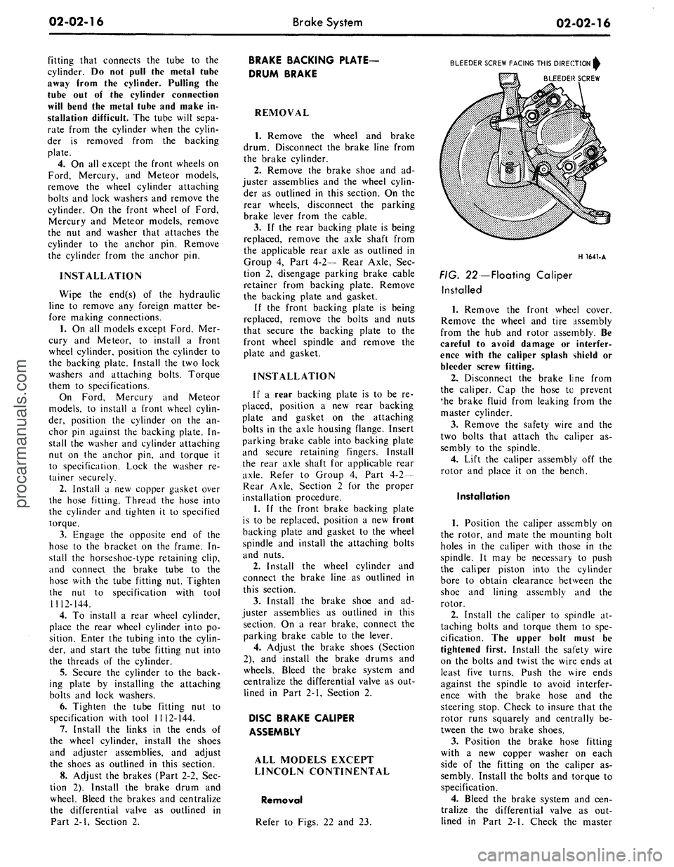
Refer to Figs. 22 and 23.
BLEEDER SCREW FACING THIS DIRECTION^
BLEEDER SCREW
H 1641-A
FIG. 22—Floating Caliper
Installed
1.
Remove the front wheel cover.
Remove the wheel and tire assembly
from the hub and rotor assembly. Be
careful to avoid damage or interfer-
ence with the caliper splash shield or
bleeder screw fitting.
2.
Disconnect the brake line from
the caliper. Cap the hose to prevent
*he brake fluid from leaking from the
master cylinder.
3.
Remove the safety wire and the
two bolts that attach the caliper as-
sembly to the spindle.
4.
Lift the caliper assembly off the
rotor and place it on the bench.
Installation
1.
Position the caliper assembly on
the rotor, and mate the mounting bolt
holes in the caliper with those in the
spindle. It may be necessary to push
the caliper piston into the cylinder
bore to obtain clearance between the
shoe and lining assembly and the
rotor.
2.
Install the caliper to spindle at-
taching bolts and torque them to spe-
cification. The upper bolt must be
tightened first. Install the safety wire
on the bolts and twist the wire ends at
least five turns. Push the wire ends
against the spindle to avoid interfer-
ence with the brake hose and the
steering stop. Check to insure that the
rotor runs squarely and centrally be-
tween the two brake shoes.
3.
Position the brake hose fitting
with a new copper washer on each
side of the fitting on the caliper as-
sembly. Install the bolts and torque to
specification.
4.
Bleed the brake system and cen-
tralize the differential valve as out-
lined in Part 2-1. Check the masterprocarmanuals.com
Page 38 of 413
02-02-19
Brake System
02-02-19
that the tabs on the shoe flanges seat
fully against the caliper bridges (Fig.
25).
2.
Install the caliper splash shield
and secure the shield to the caliper
with two retaining bolts (Fig. 4).
3.
Pump the brake pedal several
times until a firm pedal is obtained
and the shoe and lining assemblies are
properly seated.
4.
Install the wheel and tire assem-
bly on the hub and rotor assembly.
5.
Check and refill the master cyl-
inder reservoir with specified brake
fluid as required.
6. Road test the car.
It should not be necessary to bleed
the system after a shoe and lining re-
placement.
FRONT WHEEL HUB AND
ROTOR ASSEMBLY-
DISC BRAKES
REMOVAL
1.
Remove the wheel and tire from
the hub (Figs. 23 and 24). Be careful
to avoid damage or interference with
the bleeder screw fitting. On Lincoln
Continental models be careful to avoid
damage to the caliper splash shield or
transfer tube.
2.
Remove the caliper assembly
from the spindle and the rotor. If the
caliper does not require servicing, it is
not necessary to disconnect the brake
hose or remove the caliper from the
vehicle. Position the caliper out of the
way, and support it with a wire to
avoid damaging the caliper or stretch-
ing the hose. Insert a clean cardboard
spacer between the linings to prevent
the piston from coming out of the cyl-
inder bore while the caliper is re-
moved.
Handle the rotor and caliper assem-
blies in such a way as to avoid defor-
mation of the rotor and nicking,
scratching or contamination of the
brake linings.
3.
Remove the grease cap from the
hub.
Remove the cotter pin, nut lock,
adjusting nut, and flat washer from
the spindle. Remove the outer bearing
cone and roller assembly.
4.
Remove the hub and rotor as-
sembly from the spindle.
INSTALLATION
1.
If the rotor is being replaced, re-
move the protective coating from the
new rotor with carburetor degreaser.
Pack a new set of bearings with speci-
fied grease (M-1C75B), and install the
inner bearing cone and roller assembly
in the inner cup. Pack grease lightly
between the lips of a new grease seal
and install the seal (Figs. 23 and 24).
If the original rotor is being in-
stalled, make sure that the grease in
the hub is clean and adequate, that
the inner bearing and grease seal are
lubricated and in good condition, and
that the rotor braking surfaces are
clean.
2.
Install the hub and rotor assem-
bly on the spindle.
3.
Lubricate and install the outer
wheel bearing, washer and adjusting
nut.
4.
Adjust the wheel bearings to
specification, and then install the nut
lock, cotter pin, and grease cap. The
wheel bearing adjustment is especially
important with disc brakes.
5. Mount the caliper assembly on
the spindle following the Disc Brake
Caliper Assembly Installation proce-
dure in this section.
DISC BRAKE ROTOR
SPLASH SHIELD
REMOVAL
1.
Remove the caliper and the hub
and rotor assembly as outlined under
Removal in the foregoing procedure
(it is not necessary to disconnect hy-
draulic connections).
2.
Remove the three bolts that at-
tach the splash shield to the spindle,
and remove the shield (Figs. 23 and
24).
3.
Remove and discard the splash
shield to spindle gasket.
INSTALLATION
1.
Install a new splash shield to
spindle gasket.
2.
If the shield is bent, straighten it
out before installation. Position the
shield to the mounting bracket, install
the attaching bolts, nuts and torque
them to specification.
3.
Install the hub and rotor assem-
bly and the caliper as outlined under
Installation in the foregoing proce-
dure.
DUAL MASTER CYLINDER—
NON POWER BRAKES
FORD, MERCURY
AND METEOR
Removal
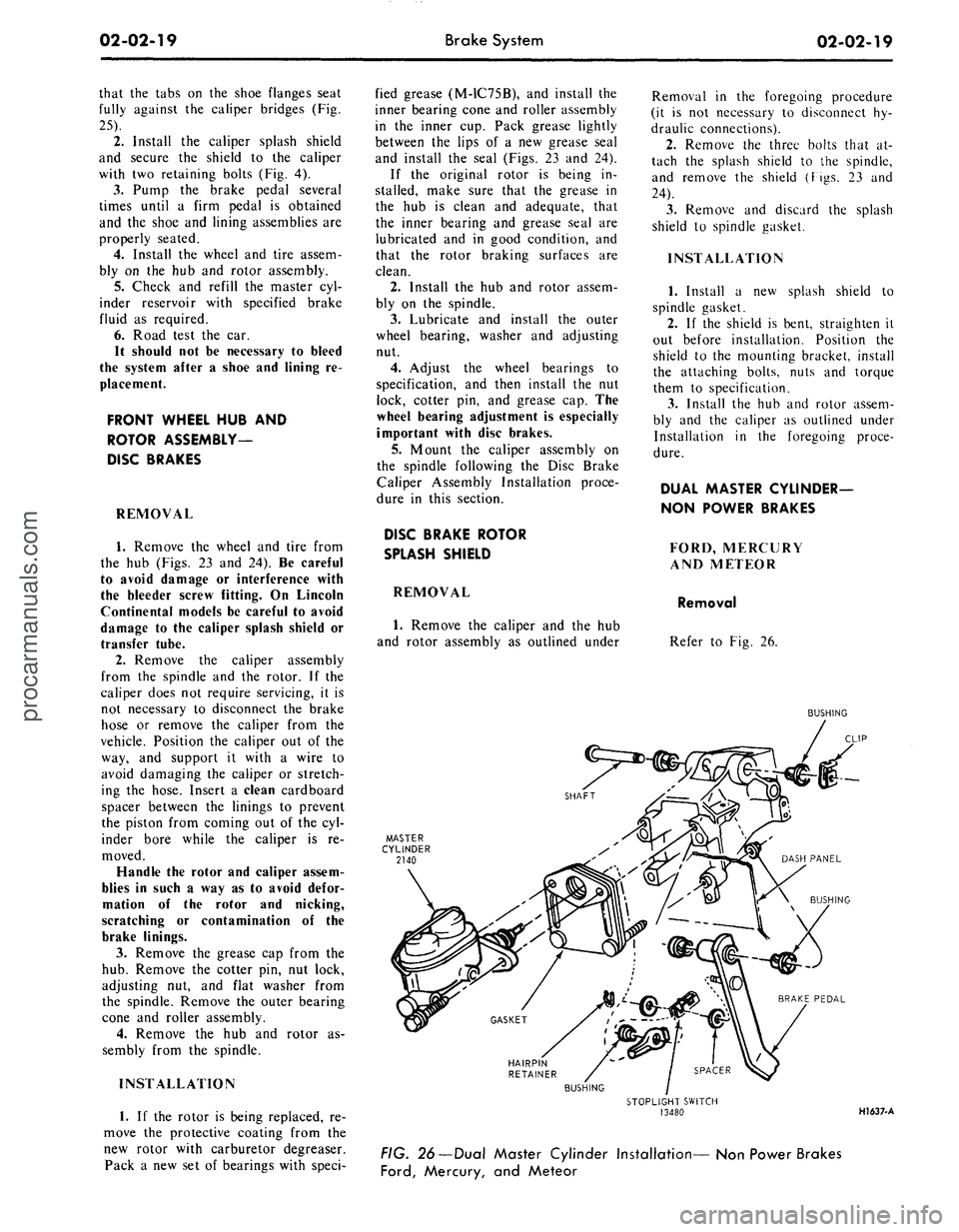
Refer to Fig. 26.
BUSHING
HAIRPIN
RETAINER
BUSHING
STOPLIGHT SWITCH
13480
HI 637-A
FIG. 26—Dual Master Cylinder Installation— Non Power Brakes
Ford,
Mercury, and Meteorprocarmanuals.com
Page 39 of 413
02-02-20
Brake System
02-02-20
1.
Disconnect the stoplight switch
wires at the connector. Remove the
spring retainer. Slide the stop light
switch off the brake pedal pin just far
enough to clear the end of the pin,
then liftfthe switch straight upward
from the pin. Use care to avoid switch
damage during removal.
2.
Slide the master cylinder push
rod and the nylon washers and bush-
ings off the brake pedal pin.
3.
Remove the brake tube from the
primary and secondary outlet ports of
the master cylinder.
4.
Remove the cap screws and lock-
washers that secure the master cylin-
der to the dirSh panel and lift the cyl-
inder forward and upward from the
vehicle.
Installation
1.
Position the boot on the push
rod and secure the boot to the master
cylinder. Carefully insert the master
cylinder push rod and boot through
the dash panel opening and position
the master cylinder on the panel.
2.
Install the cap screws at the dash
panel and torque them to specifica-
tion.
3.
Coat the nylon bushings with
SAE 10W oil. Install the nylon wash-
er and bushing on the brake pedal pin.
4.
Position the stop light switch on
the brake pedal pin, install the nylon
bushing and washer and secure them
in position with the spring retainer.
5.
Connect the wires at the stop
light switch connector.
6. Connect the brake lines to the
master cylinder leaving the brake line
fittings loose.
7.
Fill the master cylinder with the
specified brake fluid to within 1/4
inch of the top of the dual reservoirs.
Use Ford Brake Fluid— Extra Heavy
Duty-Part Number C6AZ-19542-A
(ESA-M6C25-A) or equivalent for all
drum brake applications. The extra
heavy duty brake system fluid is col-
ored blue for identification. Do not
mix low temperature brake fluids with
the specified fluid for the power disc
brake system.
8. Bleed the dual-master cylinder
and the primary and secondary brake
systems. Centralize the pressure dif-
ferential valve. Refer to Hydraulic
System Bleeding and Centralizing of
the Differential Valve, Part 2-1, Sec-
tion 2 for proper procedure.
9. Operate the brakes several times,
then check for external hydraulic
leaks.
FAIRLANE, MONTEGO,
FALCON, MUSTANG AND
COUGAR
Removal
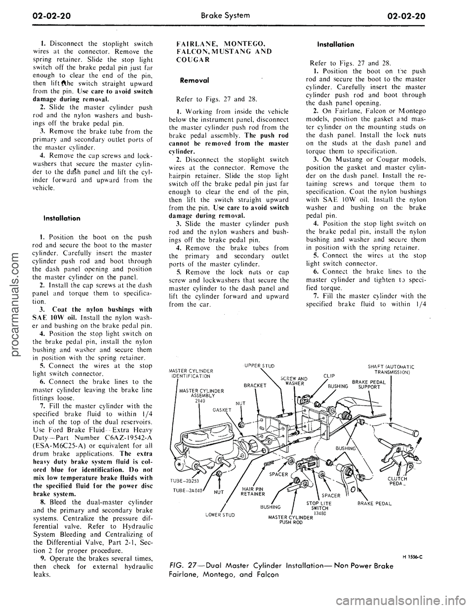
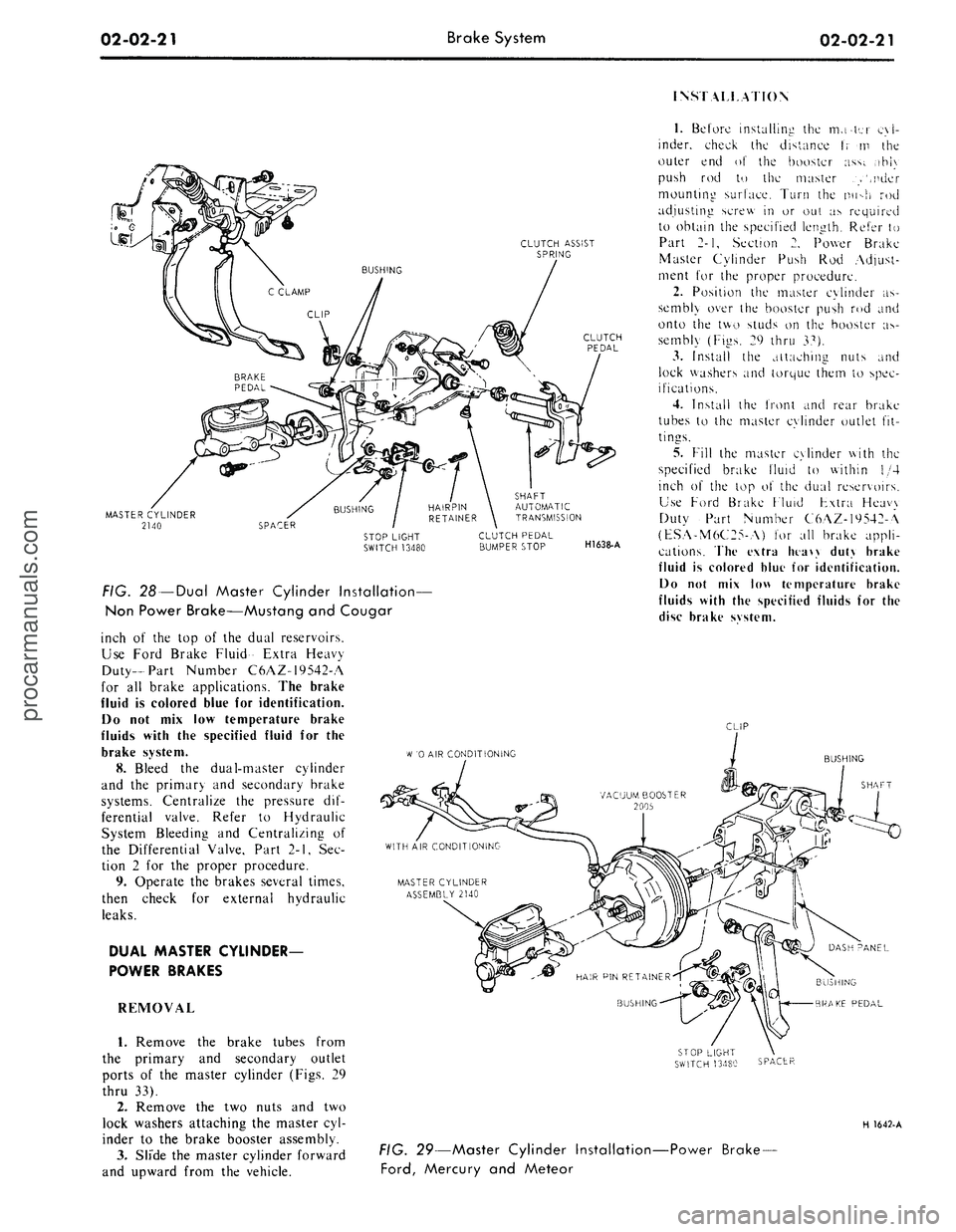
Refer to Figs. 27 and 28.
1.
Working from inside the vehicle
below the instrument panel, disconnect
the master cylinder push rod from the
brake pedal assembly. The push rod
cannot be removed from the master
cylinder.
2.
Disconnect the stoplight switch
wires at the connector. Remove the
hairpin retainer. Slide the stop light
switch off the brake pedal pin just far
enough to clear the end of the pin,
then lift the switch straight upward
from the pin. Use care to avoid switch
damage during removal.
3.
Slide the master cylinder push
rod and the nylon washers and bush-
ings off the brake pedal pin.
4.
Remove the brake tubes from
the primary and secondary outlet
ports of the master cylinder.
5.
Remove the lock nuts or cap
screw and lockwashers that secure the
master cylinder to the dash panel and
lift the cylinder forward and upward
from the car.
Installation
Refer to Figs. 27 and 28.
1.
Position the boot on tie push
rod and secure the boot to the master
cylinder. Carefully insert the master
cylinder push rod and boot through
the dash panel opening.
2.
On Fairlane, Falcon or Montego
models, position the gasket and mas-
ter cylinder on the mounting studs on
the dash panel. Install the lock nuts
on the studs at the dash panel and
torque them to specification.
3.
On Mustang or Cougar models,
position the gasket and master cylin-
der on the dash panel. Install the re-
taining screws and torque them to
specification. Coat the nylon bushings
with SAE 10W oil. Install the nylon
washer and bushing on the brake
pedal pin.
4.
Position the stop light switch on
the brake pedal pin, install the nylon
bushing and washer and secure them
in position with the spring retainer.
5.
Connect the wires at the stop
light switch connector.
6. Connect the brake lines to the
master cylinder and tighten to speci-
fied torque.
7.
Fill the master cylinder with the
specified brake fluid to within 1/4
MASTER CYLINDER
IDENTIFICATION
UPPER STUD
SHAFT (AUTOf/lATIC
TRANSMISSION)
CLIP
BRAKE PEDAL
BUSHING SUPPORT
TUBE-2B253
TUBE-2A040
CLUTCH
PEDA_
LOWER STUD
STOP LITE
SWITCH
/ 13480
MASTER CYLINDER
PUSH ROD
BRAKE PEDAL
H 1556-C
FIG. 27—Dual Master Cylinder Installation—Non Power Brake
Fairlane, Montego, and Falconprocarmanuals.com
Page 40 of 413
02-02-21
Brake System
02-02-21
INSTALLATION
CLUTCH ASSIST
SPRING
MASTER CYLINDER
2140
FIG. 28 —Dual Master Cylinder Installation—
Non Power Brake—Mustang and Cougar
inch of the top of the dual reservoirs.
Use Ford Brake Fluid- Extra Heavy
Duty-Part Number C6AZ-19542-A
for all brake applications. The brake
fluid is colored blue for identification.
Do not mix low temperature brake
fluids with the specified fluid for the
brake system.
8. Bleed the dual-master cylinder
and the primary and secondary brake
systems. Centralize the pressure dif-
ferential valve. Refer to Hydraulic
System Bleeding and Centralizing of
the Differential Valve, Part 2-1, Sec-
tion 2 for the proper procedure.
9. Operate the brakes several times,
then check for external hydraulic
leaks.
DUAL MASTER CYLINDER-
POWER BRAKES
REMOVAL
1.
Remove the brake tubes from
the primary and secondary outlet
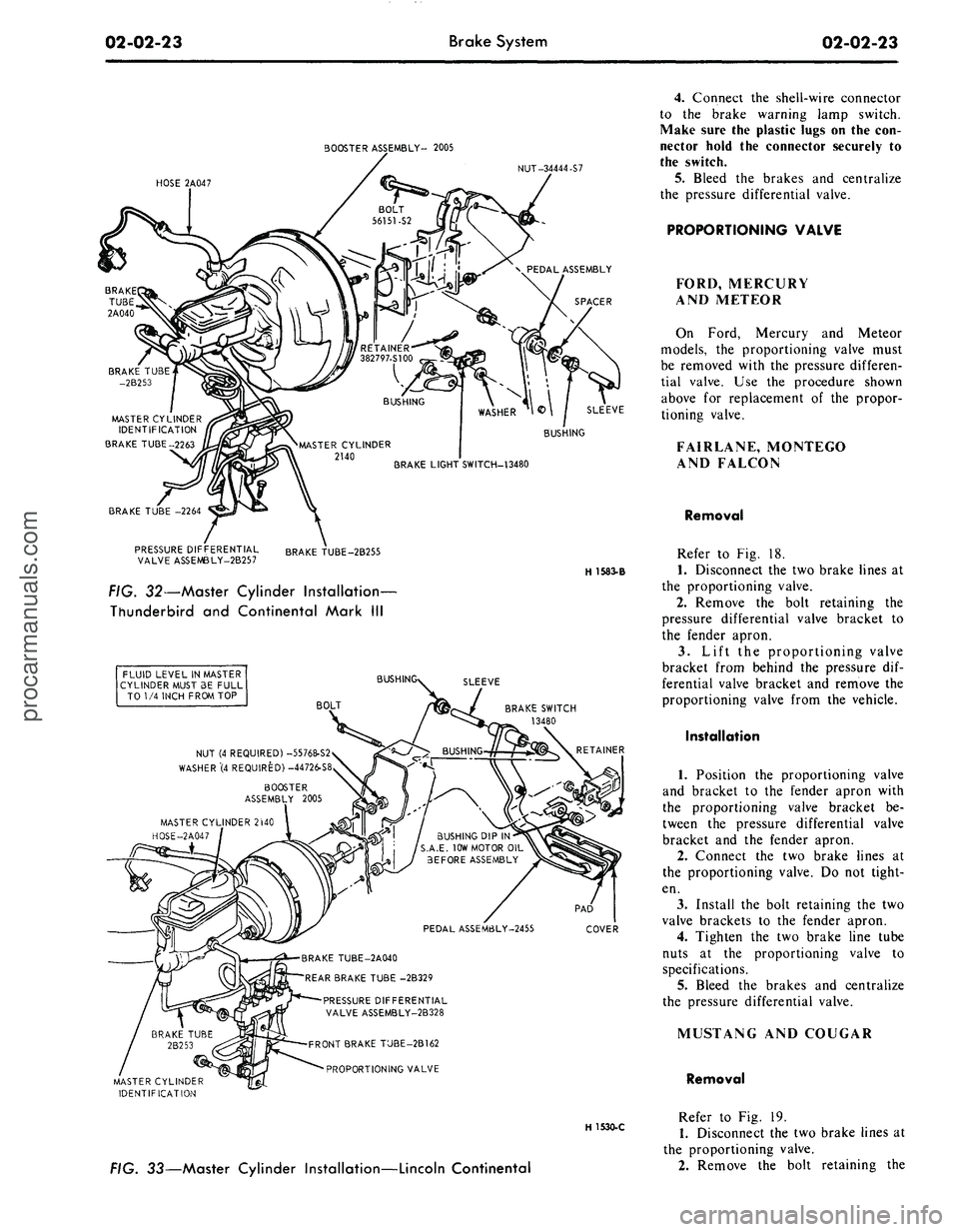
ports of the master cylinder (Figs. 29
thru 33).
2.
Remove the two nuts and two
lock washers attaching the master cyl-
inder to the brake booster assembly.
3.
Slide the master cylinder forward
and upward from the vehicle.
SHAFT
AUTOMATIC
TRANSMISSION
CLUTCH PEDAL
BUMPER STOP
H1638-A
1.
Before installing the mater cyl-
inder, check the distance t; m the
outer end of the booster ass;. ,ihi\
push rod to the master .>',nder
mounting surface. Turn the nu->h rod
adjusting screw in or out as required
to obtain the specified length. Refer to
Part 2-1, Section 2. Power Brake
Master Cylinder Push Rod Adjust-
ment for the proper procedure.
2.
Position the master cylinder as-
sembly over the booster push rod and
onto the two studs on the booster as-
sembly (Figs. 29 thru 37).
3.
Install the attaching nuts and
lock washers and torque them to spec-
ifications.
4.
Install the front and rear brake
tubes to the master cylinder outlet fit-
tings.
5.
Fill the master cylinder with the
specified brake fluid to within 1/4
inch of the top o\ the dual reservoirs.
Use Ford Brake Fluid Fxtra Heavy
Duty Part Number C6AZ-19542-A
(ESA-M6C25-A) for all brake appli-
cations. The extra htaw duty brake
fluid is colored blue for identification.
Do not mix low temperature brake
fluids with the specified fluids for the
disc brake svstem.
CLIP
W
'0 AIR CONDITIONING
BUSHING
SHAFT
BUSHING
BRAKE PEDAL
SPACER
H 1642-A
FIG. 29—Master Cylinder Installation-
Ford,
Mercury and Meteor
-Power Brake-procarmanuals.com
Page 42 of 413
02-02-23
Brake System
02-02-23
BOOSTER ASSEMBLY- 2005
NUT-34444-S7
HOSE 2A047
MASTER CYLINDER
IDENTIFICATION
BRAKE TUBE-2263
BRAKE TUBE -2264
PRESSURE DIFFERENTIAL
VALVE ASSEMBLY-2B257
BRAKE TUBE-2B255
H 15S3-B
FIG. 32—Master Cylinder Installation-
Thunderbird and Continental Mark III
FLUID LEVEL IN MASTER
CYLINDER MUST 3E FULL
TO 1/4 INCH FROM TOP
BUSH
SLEEVE
BOLT
BRAKE SWITCH
13480
NUT (4 REQUIRED) -55768-S2
WASHER"(4 REQUIRED) -44726-S8
BOOSTER
ASSEMBLY 2005
MASTER CYLINDER 2WO
HOSE-2A047
BUSHING DIP IN
S.A.E. 10W MOTOR OIL
BEFORE ASSEMBLY
PEDAL ASSEM6LY-2455
COVER
BRAKE TUBE-2A040
REAR BRAKE TUBE -2B329
PRESSURE DIFFERENTIAL
VALVE ASSEMBLY-2B328
FRONT BRAKE TUBE-2B162
PROPORTIONING VALVE
MASTER CYLINDER
IDENTIFICATION
H 1530-C
FIG. 33—Master Cylinder Installation—Lincoln Continental
4.
Connect the shell-wire connector
to the brake warning lamp switch.
Make sure the plastic lugs on the con-
nector hold the connector securely to
the switch.
5. Bleed the brakes and centralize
the pressure differential valve.
PROPORTIONING VALVE
FORD, MERCURY
AND METEOR
On Ford, Mercury and Meteor
models, the proportioning valve must
be removed with the pressure differen-
tial valve. Use the procedure shown
above for replacement of the propor-
tioning valve.
FAIRLANE, MONTEGO
AND FALCON
Removal
Refer to Fig. 18.
1.
Disconnect the two brake lines at
the proportioning valve.
2.
Remove the bolt retaining the
pressure differential valve bracket to
the fender apron.
3.
Lift the proportioning valve
bracket from behind the pressure dif-
ferential valve bracket and remove the
proportioning valve from the vehicle.
Installation
1.
Position the proportioning valve
and bracket to the fender apron with
the proportioning valve bracket be-
tween the pressure differential valve
bracket and the fender apron.
2.
Connect the two brake lines at
the proportioning valve. Do not tight-
en.
3.
Install the bolt retaining the two
valve brackets to the fender apron.
4.
Tighten the two brake line tube
nuts at the proportioning valve to
specifications.
5.
Bleed the brakes and centralize
the pressure differential valve.
MUSTANG AND COUGAR
Removal
Refer to Fig. 19.
1.
Disconnect the two brake lines at
the proportioning valve.
2.
Remove the bolt retaining theprocarmanuals.com
Page 112 of 413
03-04-03
Automatic Air Leveling System — Lincoln Continental
03-04-03
outlet lines to their respective parts.
3.
Adjust the trim height as de-
tailed in Section 4.
4.
Connect the link to the arm.
5.
Remove the jack stands and
lower the vehicle.
SUPER LIFT SHOCK ABSORBER
REMOVAL
1.
Raise the vehicle and place jack
stands under the axle to compress the
super lift.
2.
Loosen the air line or lines (right
super lift) slowly to release the air
from the system. Then, disconnect the
line or lines.
3.
Remove the three mounting plate
attaching screws from the upper end
of the super lift.
4.
Remove the attaching nut and
washer from the lower end of the
super lift and remove it from the vehi-
cle.
5.
Remove the nut, outer washer
and the insulator that attach the super
lift to the mounting plate. Remove the
plate, remaining insulator and washer.
INSTALLATION
1.
Position a washer, insulator,
mounting plate, insulator, washer and
nut on the stud at the upper end of
the super lift. Torque the nut to speci-
fication.
2.
Install the mounting plate, outer
insulator, washer and nut on the stud.
Torque the nut to specification.
3.
Attach the mounting plate and
shock absorber to the crossmember
with the attaching screws to specifica-
tions.
4.
Connect the lower end of the
super lift to the mounting stud with
the washers and attaching nut. Torque
the nut to specification.
5.
Connect the air line or lines
(right super lift) to the super lift.
6. Start the engine and check for
leaks.
3 IN-VEHICLE ADJUSTMENTS AND REPAIRS
REGULATOR ADJUSTMENT HEIGHT CONTROL VALVE
The regulator may be adjusted if
the regulator pressure is under 100 psi
with the reservoir pressure at a mini-
mum of 140 psi. If the regulated pres-
sure exceeds 130 psi, the regulator
must be replaced.
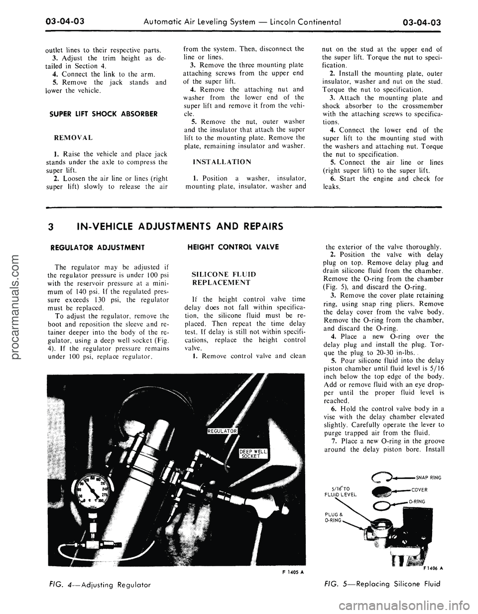
To adjust the regulator, remove the
boot and reposition the sleeve and re-
tainer deeper into the body of the re-
gulator, using a deep well socket (Fig.
4).
If the regulator pressure remains
under 100 psi, replace regulator.
SILICONE FLUID
REPLACEMENT
If the height control valve time
delay does not fall within specifica-
tion, the silicone fluid must be re-
placed. Then repeat the time delay
test. If delay is still not within specifi-
cations, replace the height control
valve.
1.
Remove control valve and clean
the exterior of the valve thoroughly.
2.
Position the valve with delay
plug on top. Remove delay plug and
drain silicone fluid from the chamber.
Remove the O-ring from the chamber
(Fig. 5), and discard the O-ring.
3.
Remove the cover plate retaining
ring, using snap ring pliers. Remove
the delay cover from the valve body.
Remove the O-ring from the chamber,
and discard the O-ring.
4.
Place a new O-ring over the
delay plug and install the plug. Tor-
que the plug to 20-30 in-lbs. .
5.
Pour silicone fluid into the delay
piston chamber until fluid level is 5/16
inch below the top edge of the body.
Add or remove fluid with an eye drop-
per until the proper fluid level is
reached.
6. Hold the control valve body in a
vise with the delay chamber elevated
slightly. Carefully operate the lever to
purge trapped air from the fluid.
7.
Place a new O-ring in the groove
around the delay piston bore. Install
5/16" TO
FLUID LEVEL
F 1405 A
FIG. 4—Adjusting Regulator
F1406 A
FIG. 5—Replacing Silicone Fluidprocarmanuals.com
Page 140 of 413
03-07-02
Ford Design Non-Integral Power Steering System
03-07-02
PUMP AND RESERVOIR
CONTROL VALVE
POWER CYLINDER
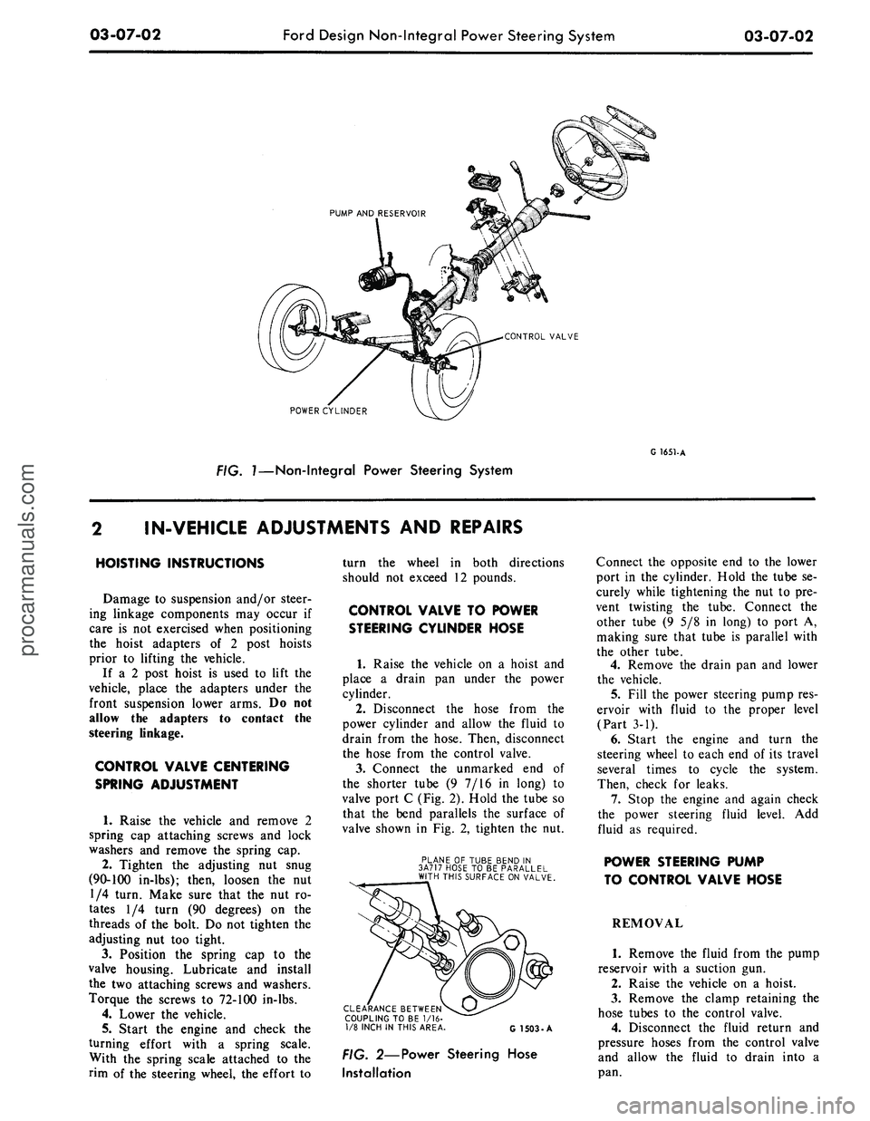
FIG. 7—Non-Integral Power Steering System
G 1651-A
IN-VEHICLE ADJUSTMENTS
AND
REPAIRS
HOISTING INSTRUCTIONS
Damage
to
suspension and/or steer-
ing linkage components
may
occur
if
care
is not
exercised when positioning
the hoist adapters
of 2
post hoists
prior
to
lifting
the
vehicle.
If
a 2
post hoist
is
used
to
lift
the
vehicle, place
the
adapters under
the
front suspension lower arms.
Do not
allow
the
adapters
to
contact
the
steering linkage.
CONTROL VALVE CENTERING
SPRING ADJUSTMENT
1.
Raise
the
vehicle
and
remove
2
spring
cap
attaching screws
and
lock
washers
and
remove
the
spring
cap.
2.
Tighten
the
adjusting
nut
snug
(90-100 in-lbs); then, loosen
the nut
1/4 turn. Make sure that
the nut ro-
tates
1/4
turn
(90
degrees)
on the
threads
of the
bolt.
Do not
tighten
the
adjusting
nut too
tight.
3.
Position
the
spring
cap to the
valve housing. Lubricate
and
install
the
two
attaching screws
and
washers.
Torque
the
screws
to
72-100 in-lbs.
4.
Lower
the
vehicle.
5.
Start
the
engine
and
check
the
turning effort with
a
spring scale.
With
the
spring scale attached
to the
rim
of the
steering wheel,
the
effort
to
turn
the
wheel
in
both directions
should
not
exceed
12
pounds.
CONTROL VALVE
TO
POWER
STEERING CYLINDER HOSE
1.
Raise
the
vehicle
on a
hoist
and
place
a
drain
pan
under
the
power
cylinder.
2.
Disconnect
the
hose from
the
power cylinder
and
allow
the
fluid
to
drain from
the
hose. Then, disconnect
the hose from
the
control valve.
3.
Connect
the
unmarked
end of
the shorter tube
(9 7/16 in
long)
to
valve port
C
(Fig. 2). Hold
the
tube
so
that
the
bend parallels
the
surface
of
valve shown
in Fig. 2,
tighten
the nut.
PLANE
OF
TUBE BEND
IN
3A717 HOSE
TO BE
PARALLEL
WITH THIS SURFACE ON VALVE.
CLEARANCE BETWEEN
COUPLING TO
BE 1/16-
1/8 INCH
IN
THIS AREA
G 1503-A
FIG. 2—Power Steering Hose
Installation
Connect
the
opposite
end to the
lower
port
in the
cylinder. Hold
the
tube
se-
curely while tightening
the nut to pre-
vent twisting
the
tube. Connect
the
other tube
(9 5/8 in
long)
to
port
A,
making sure that tube
is
parallel with
the other tube.
4.
Remove
the
drain
pan and
lower
the vehicle.
5.
Fill
the
power steering pump res-
ervoir with fluid
to the
proper level
(Part
3-1).
6. Start
the
engine
and
turn
the
steering wheel
to
each
end of its
travel
several times
to
cycle
the
system.
Then, check
for
leaks.
7.
Stop
the
engine
and
again check
the power steering fluid level.
Add
fluid
as
required.
POWER STEERING PUMP
TO CONTROL VALVE HOSE
REMOVAL
1.
Remove
the
fluid from
the
pump
reservoir with
a
suction
gun.
2.
Raise
the
vehicle
on a
hoist.
3.
Remove
the
clamp retaining
the
hose tubes
to the
control valve.
4.
Disconnect
the
fluid return
and
pressure hoses from
the
control valve
and allow
the
fluid
to
drain into
a
pan.procarmanuals.com
Page 142 of 413
03-07-04
Ford Design Non-Integral Power Steering System
03-07-04
12.
Stop the engine, and check the
control valve and hose connections for
fluid leaks. Correct the cause of any
leaks.
13.
Check the fluid level, and refill
the reservoir if necessary.
14.
With the engine running check
the position of the steering wheel
when the front wheels are in the
straight-ahead position.Do not make
any adjustments until toe-in is
checked.
15.
Keep the engine running, and
check toe-in. If either toe-in or steer-
ing wheel position is not correct make
all necessary adjustments (Part 3-1) at
the spindle connecting rod sleeves.
16.
Check the effort to turn the
wheels in both directions. The effort
should be about equal in both direc-
tions.
POWER CYLINDER
REMOVAL
1.
Disconnect the two fluid lines
from the power cylinder and allow
them to drain into a container.
CENTER LINK
POWER CYLINDER
Tool- T64P-3590-F
G 1654-A
FIG. 5—Disconnecting Power
Cylinder Stud
2.
Remove the 'pal nut, attaching
nut, washer and the insulator from the
end of the power cylinder rod.
3.
Remove the cotter pin and cas-
tellated nut that secures the power
cylinder stud to the center link.
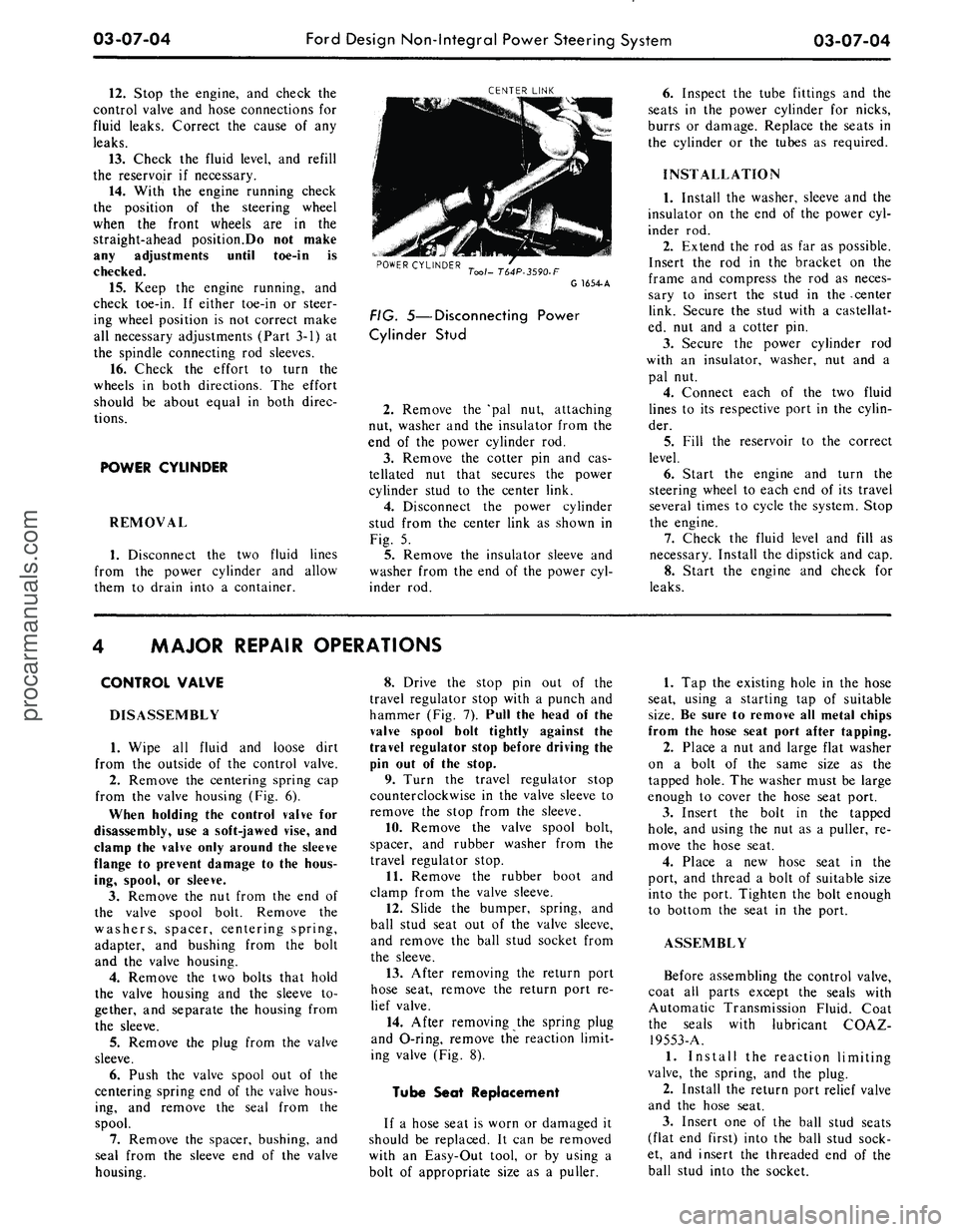
4.
Disconnect the power cylinder
stud from the center link as shown in
Fig. 5.
5.
Remove the insulator sleeve and
washer from the end of the power cyl-
inder rod.
6. Inspect the tube fittings and the
seats in the power cylinder for nicks,
burrs or damage. Replace the seats in
the cylinder or the tubes as required.
INSTALLATION
1.
Install the washer, sleeve and the
insulator on the end of the power cyl-
inder rod.
2.
Extend the rod as far as possible.
Insert the rod in the bracket on the
frame and compress the rod as neces-
sary to insert the stud in the -center
link. Secure the stud with a castellat-
ed, nut and a cotter pin.
3.
Secure the power cylinder rod
with an insulator, washer, nut and a
pal nut.
4.
Connect each of the two fluid
lines to its respective port in the cylin-
der.
5.
Fill the reservoir to the correct
level.
6. Start the engine and turn the
steering wheel to each end of its travel
several times to cycle the system. Stop
the engine.
7.
Check the fluid level and fill as
necessary. Install the dipstick and cap.
8. Start the engine and check for
leaks.
MAJOR REPAIR OPERATIONS
CONTROL VALVE
DISASSEMBLY
1.
Wipe all fluid and loose dirt
from the outside of the control valve.
2.
Remove the centering spring cap
from the valve housing (Fig. 6).
When holding the control valve for
disassembly, use a soft-jawed vise, and
clamp the valve only around the sleeve
flange to prevent damage to the hous-
ing, spool, or sleeve.
3.
Remove the nut from the end of
the valve spool bolt. Remove the
washers, spacer, centering spring,
adapter, and bushing from the bolt
and the valve housing.
4.
Remove the two bolts that hold
the valve housing and the sleeve to-
gether, and separate the housing from
the sleeve.
5.
Remove the plug from the valve
sleeve.
6. Push the valve spool out of the
centering spring end of the valve hous-
ing, and remove the seal from the
spool.
7.
Remove the spacer, bushing, and
seal from the sleeve end of the valve
housing.
8. Drive the stop pin out of the
travel regulator stop with a punch and
hammer (Fig. 7). Pull the head of the
valve spool bolt tightly against the
travel regulator stop before driving the
pin out of the stop.
9. Turn the travel regulator stop
counterclockwise in the valve sleeve to
remove the stop from the sleeve.
10.
Remove the valve spool bolt,
spacer, and rubber washer from the
travel regulator stop.
11.
Remove the rubber boot and
clamp from the valve sleeve.
12.
Slide the bumper, spring, and
ball stud seat out of the valve sleeve,
and remove the ball stud socket from
the sleeve.
13.
After removing the return port
hose seat, remove the return port re-
lief valve.
14.
After removing the spring plug
and O-ring, remove the reaction limit-
ing valve (Fig. 8).
Tube Seat Replacement
If a hose seat is worn or damaged it
should be replaced. It can be removed
with an Easy-Out tool, or by using a
bolt of appropriate size as a puller.
1.
Tap the existing hole in the hose
seat, using a starting tap of suitable
size.
Be sure to remove all metal chips
from the hose seat port after tapping.
2.
Place a nut and large flat washer
on a bolt of the same size as the
tapped hole. The washer must be large
enough to cover the hose seat port.
3.
Insert the bolt in the tapped
hole,
and using the nut as a puller, re-
move the hose seat.
4.
Place a new hose seat in the
port, and thread a bolt of suitable size
into the port. Tighten the bolt enough
to bottom the seat in the port.
ASSEMBLY
Before assembling the control valve,
coat all parts except the seals with
Automatic Transmission Fluid. Coat
the seals with lubricant COAZ-
19553-A.
1.
Install the reaction limiting
valve, the spring, and the plug.
2.
Install the return port relief valve
and the hose seat.
3.
Insert one of the ball stud seats
(flat end first) into the ball stud sock-
et, and insert the threaded end of the
ball stud into the socket.procarmanuals.com
Page 150 of 413
03-08-06
Ford Design Integral Power Steering Gear
03-08-06
VALVE HOUSING
7W-T65P
C1239 -A
FIG. 7—Removing or Installing Lock
Nut
drain the remaining fluid from the
gear.
2.
Mount the gear in a soft-jawed
vise.
3.
Remove the lock nut and the
brass washer from the adjusting screw.
4.
Turn the input shaft to either
stop then, turn it back approximately
1 3/4 turns to center the gear.
5.
Remove the two sector shaft
cover attaching screws and the
identif-
ication tag.
6. Tap the lower end of the sector
shaft with a soft-hammer to loosen it,
then lift the cover and shaft from the
housing as an assembly. Discard the
O-ring.
7.
Turn the sector shaft cover coun-
terclockwise off the adjuster screw.
8. Remove the four valve housing
attaching bolts. Lift the valve housing
from the steering gear housing while
holding the piston to prevent it from
rotating off the worm shaft. Remove
the valve housing and the lube passage
O-rings and discard them.
9. Stand the valve body and piston
on end with the piston end down. Ro-
tate the input shaft counterclockwise
out of the piston allowing the ball
bearings to drop into the piston.
10.
Place a cloth over the open end
of the piston and turn it upside down
to remove the balls.
11.
Remove the two screws that at-
tach the ball guide clamp (Fig. 6) to
the ball nut and remove the clamp and
the guides.
12.
Install the valve body assembly
in the holding fixture (do not clamp
in a vise) and remove the lock nut and
the attaching nut as shown in Fig. 7.
13.
Carefully slide the input shaft,
worm and valve assembly out of the
valve housing. Due to the close diame-
trical clearance between the spool and
housing, the slightest cocking of the
spool may cause it to jam in the hous-
ing.
14.
Remove the shim from the
valve housing bore.
OIL SEAL
INLET TUBE SEAT
OUTLET TUBE SEAT
DUST SEAL
G1549-A
FIG.
8—Valve Housing Disassembled
Too/-T<
Tool-
T57L-500-A ,^^^
G1364-A
FIG. 9—Removing Bearing and Oil
Seal
PARTS REPAIR
OR REPLACEMENT
Valve Housing
1.
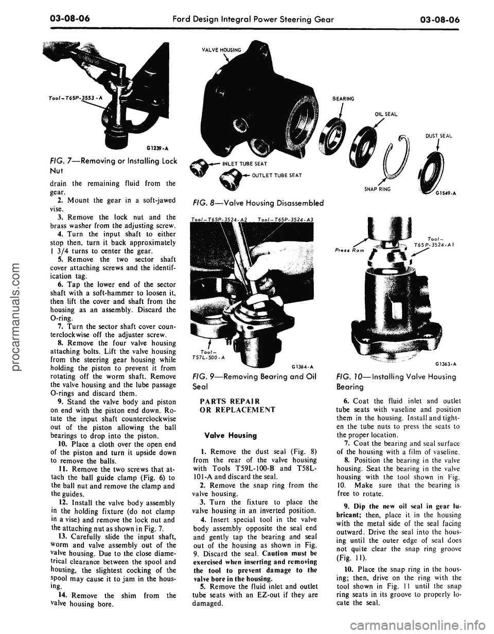
Remove the dust seal (Fig. 8)
from the rear of the valve housing
with Tools T59L-100-B and T58L-
101-A and discard the seal.
2.
Remove the snap ring from the
valve housing.
3.
Turn the fixture to place the
valve housing in an inverted position.
4.
Insert special tool in the valve
body assembly opposite the seal end
and gently tap the bearing and seal
out of the housing as shown in Fig.
9. Discard the seal. Caution must be
exercised when inserting and removing
the tool to prevent damage to the
valve bore in the housing.
5.
Remove the fluid inlet and outlet
tube seats with an EZ-out if they are
damaged.
Press Ra
Tool-
T65P-3524-A7
G1363-A
FIG. 10—Installing Valve Housing
Bearing
6. Coat the fluid inlet and outlet
tube seats with vaseline and position
them in the housing. Install and tight-
en the tube nuts to press the seats to
the proper location.
7.
Coat the bearing and seal surface
of the housing with a film of vaseline.
8. Position the bearing in the valve
housing. Seat the bearing in the valve
housing with the tool shown in Fig.
10.
Make sure that the bearing is
free to rotate.
9. Dip the new oil seal in gear lu-
bricant; then, place it in the housing
with the metal side of the seal facing
outward. Drive the seal into the hous-
ing until the outer edge of seal does
not quite clear the snap ring groove
(Fig. 11).
10.
Place the snap ring in the hous-
ing; then, drive on the ring with the
tool shown in Fig. 11 until the snap
ring seats in its groove to properly lo-
cate the seal.procarmanuals.com