air condition FORD MUSTANG 1969 Volume One Chassis
[x] Cancel search | Manufacturer: FORD, Model Year: 1969, Model line: MUSTANG, Model: FORD MUSTANG 1969Pages: 413, PDF Size: 75.81 MB
Page 14 of 413
02-01-03
Brakes
02-01-03
vacuum system is operating, the pedal
will tend to fall away under foot pres-
sure and less pressure will be required
to hold the pedal in the applied posi-
tion. If no action is felt, the vacuum
booster system is not functioning.
If the brake pedal movement feels
spongy, bleed the hydraulic system to
remove air from the system. Refer to
Hydraulic System Bleeding, Part 1,
Section 2.
VACUUM TESTS—VACUUM
RELEASE PARKING BRAKES
Visually check the operation of the
brake linkage as the brake pedal is
depressed. Then, check the operation
of the brake linkage when the manual
release lever is activiated. These
checks should indicate whether the
manual parking brake control linkage
is operating properly or requires re-
pair or adjustment due to inability of
the parking brake to hold against
moderate vehicle movement. Perform
tests of the parking brake system and
controls after making certain the link-
age and manual controls operate
properly.
When testing a parking brake vacu-
um release system, a minimum of 10
inches of vacuum (Hg.) should be
available at all points where vacuum is
applied. This can be checked with a
Rotunda Fuel Pump Tester Gauge
(ARE345) and two Distributor Tester
hose adapters (Marked Q) connected
together with a coupling. This allows
the Fuel Pump Tester Gauge hose to
be adapted to any other vacuum hose
or rubber connector in the vacuum
systems.
Failure to maintain 10 inches of
vacuum (Hg.) during vacuum system
tests could be caused by a loose hose
connection, resulting in a vacuum
leak. When checking for vacuum be-
tween two points, trace the hose along
the entire routing to be sure it is not
crossed with another hose and con-
nected to the wrong connection.
All of the vacuum parking brake
control checks are to be performed
with the engine running at idle speed.
Leaks in the parking brake hoses or
a disconnected or improperly con-
nected hose can usually be found by
listening for a hissing sound along the
hose routings. Under no circumstances
should air pressure be applied to the
vacuum system as the actuator dia-
phragm in the parking brake vacuum
motor may be damaged.
1.
Start the engine and run it at
idle speed. With the transmission shift
control in neutral, depress the parking
brake pedal to apply the parking
brake. Move the transmission shift
control to D range and observe the
parking brake pedal to see that the
pedal moves upward and the parking
brake releases. If the parking brake
releases, the parking brake vacuum
control is working properly.
2.
If the parking brake does not re-
lease, test for vacuum at the steering
column neutral switch port in the
junction block, vacuum lines and the
parking brake release vacuum motor.
Use the Rotunda Vacuum and Fuel
Pump Tester 345. This can be accom-
plished by removing the hose from
each component and attaching it to
the vacuum gauge. Connect two dis-
tributor tester vacuum hose adapters
together with a coupling as a connec-
tor to attach the gauge. A minimum
of ten inches of vacuum is required to
actuate the parking brake vacuum
motor. Do not remove any of the vac-
uum hoses from the junction block
unless the junction block is being re-
placed, as the plastic nipples are thin
and very brittle and damage may re-
sult. If a minimum reading is not
present when checking each of the
aforementioned components, they
must be replaced.
ROAD TEST
A road test should be conducted
only when the operator is sure the
brakes will stop the vehicle.
If the road test reveals one or more
problem conditions, correct all mal-
functions of the vacuum system, brake
booster and hydraulic system prior to
removing brake drums, brake calipers,
brake shoes and linings or backing
plates.
ANTI-SKID CONTROL
SYSTEM TESTS
No adjustments or repairs are to be
performed on the skid control system.
Damaged or worn parts are to be re-
placed.
Refer to Ford Car and Truck Diag-
nosis Manual for Testing procedures.
COMMON ADJUSTMENTS AND REPAIRS
PARKING BRAKE LINKAGE
ADJUSTMENT
FORD, MERCURY, METEOR,
FAIRLANE, MONTEGO,
FALCON, MUSTANG
AND COUGAR
Check the parking brake cables
when the brakes are fully released. If1
the cables are loose, adjust them as
follows:
1.
Fully release the parking brake
pedal by pulling the release lever.
2.
Depress the parking brake pedal
until it is engaged in the first notch of
the control. On a vacuum release
brake, the first notch will be approxi-
mately two inches of pedal travel.
3.
Raise the vehicle. With the
transmission in neutral, turn the ad-
justing nut forward against the equal-
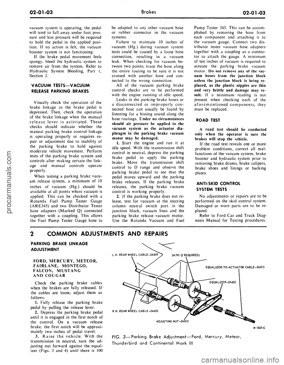
izer (Figs. 3 and 4) until there is 100
L.H. REAR WHEEL CABLE -2A809> 2A791 (2 REQUIRED)
EQUALIZER-TO-ACTUATOR CABLE-2A815
R.H. REAR WHEEL CABLE-2A635
ADJUSTING NUT-2A812
H 1537-C
FIG. 3—Parking Brake Adjustment—Ford, Mercury, Meteor,
Thunderbird and Continental Mark IIIprocarmanuals.com
Page 38 of 413
02-02-19
Brake System
02-02-19
that the tabs on the shoe flanges seat
fully against the caliper bridges (Fig.
25).
2.
Install the caliper splash shield
and secure the shield to the caliper
with two retaining bolts (Fig. 4).
3.
Pump the brake pedal several
times until a firm pedal is obtained
and the shoe and lining assemblies are
properly seated.
4.
Install the wheel and tire assem-
bly on the hub and rotor assembly.
5.
Check and refill the master cyl-
inder reservoir with specified brake
fluid as required.
6. Road test the car.
It should not be necessary to bleed
the system after a shoe and lining re-
placement.
FRONT WHEEL HUB AND
ROTOR ASSEMBLY-
DISC BRAKES
REMOVAL
1.
Remove the wheel and tire from
the hub (Figs. 23 and 24). Be careful
to avoid damage or interference with
the bleeder screw fitting. On Lincoln
Continental models be careful to avoid
damage to the caliper splash shield or
transfer tube.
2.
Remove the caliper assembly
from the spindle and the rotor. If the
caliper does not require servicing, it is
not necessary to disconnect the brake
hose or remove the caliper from the
vehicle. Position the caliper out of the
way, and support it with a wire to
avoid damaging the caliper or stretch-
ing the hose. Insert a clean cardboard
spacer between the linings to prevent
the piston from coming out of the cyl-
inder bore while the caliper is re-
moved.
Handle the rotor and caliper assem-
blies in such a way as to avoid defor-
mation of the rotor and nicking,
scratching or contamination of the
brake linings.
3.
Remove the grease cap from the
hub.
Remove the cotter pin, nut lock,
adjusting nut, and flat washer from
the spindle. Remove the outer bearing
cone and roller assembly.
4.
Remove the hub and rotor as-
sembly from the spindle.
INSTALLATION
1.
If the rotor is being replaced, re-
move the protective coating from the
new rotor with carburetor degreaser.
Pack a new set of bearings with speci-
fied grease (M-1C75B), and install the
inner bearing cone and roller assembly
in the inner cup. Pack grease lightly
between the lips of a new grease seal
and install the seal (Figs. 23 and 24).
If the original rotor is being in-
stalled, make sure that the grease in
the hub is clean and adequate, that
the inner bearing and grease seal are
lubricated and in good condition, and
that the rotor braking surfaces are
clean.
2.
Install the hub and rotor assem-
bly on the spindle.
3.
Lubricate and install the outer
wheel bearing, washer and adjusting
nut.
4.
Adjust the wheel bearings to
specification, and then install the nut
lock, cotter pin, and grease cap. The
wheel bearing adjustment is especially
important with disc brakes.
5. Mount the caliper assembly on
the spindle following the Disc Brake
Caliper Assembly Installation proce-
dure in this section.
DISC BRAKE ROTOR
SPLASH SHIELD
REMOVAL
1.
Remove the caliper and the hub
and rotor assembly as outlined under
Removal in the foregoing procedure
(it is not necessary to disconnect hy-
draulic connections).
2.
Remove the three bolts that at-
tach the splash shield to the spindle,
and remove the shield (Figs. 23 and
24).
3.
Remove and discard the splash
shield to spindle gasket.
INSTALLATION
1.
Install a new splash shield to
spindle gasket.
2.
If the shield is bent, straighten it
out before installation. Position the
shield to the mounting bracket, install
the attaching bolts, nuts and torque
them to specification.
3.
Install the hub and rotor assem-
bly and the caliper as outlined under
Installation in the foregoing proce-
dure.
DUAL MASTER CYLINDER—
NON POWER BRAKES
FORD, MERCURY
AND METEOR
Removal
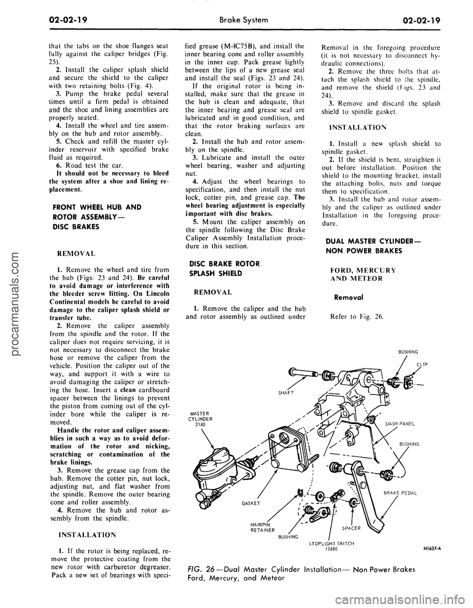
Refer to Fig. 26.
BUSHING
HAIRPIN
RETAINER
BUSHING
STOPLIGHT SWITCH
13480
HI 637-A
FIG. 26—Dual Master Cylinder Installation— Non Power Brakes
Ford,
Mercury, and Meteorprocarmanuals.com
Page 40 of 413
02-02-21
Brake System
02-02-21
INSTALLATION
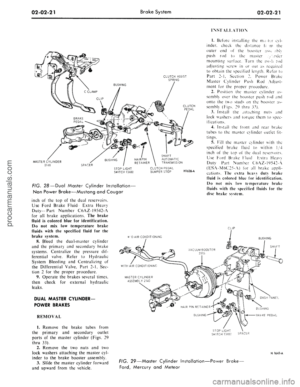
CLUTCH ASSIST
SPRING
MASTER CYLINDER
2140
FIG. 28 —Dual Master Cylinder Installation—
Non Power Brake—Mustang and Cougar
inch of the top of the dual reservoirs.
Use Ford Brake Fluid- Extra Heavy
Duty-Part Number C6AZ-19542-A
for all brake applications. The brake
fluid is colored blue for identification.
Do not mix low temperature brake
fluids with the specified fluid for the
brake system.
8. Bleed the dual-master cylinder
and the primary and secondary brake
systems. Centralize the pressure dif-
ferential valve. Refer to Hydraulic
System Bleeding and Centralizing of
the Differential Valve, Part 2-1, Sec-
tion 2 for the proper procedure.
9. Operate the brakes several times,
then check for external hydraulic
leaks.
DUAL MASTER CYLINDER-
POWER BRAKES
REMOVAL
1.
Remove the brake tubes from
the primary and secondary outlet
ports of the master cylinder (Figs. 29
thru 33).
2.
Remove the two nuts and two
lock washers attaching the master cyl-
inder to the brake booster assembly.
3.
Slide the master cylinder forward
and upward from the vehicle.
SHAFT
AUTOMATIC
TRANSMISSION
CLUTCH PEDAL
BUMPER STOP
H1638-A
1.
Before installing the mater cyl-
inder, check the distance t; m the
outer end of the booster ass;. ,ihi\
push rod to the master .>',nder
mounting surface. Turn the nu->h rod
adjusting screw in or out as required
to obtain the specified length. Refer to
Part 2-1, Section 2. Power Brake
Master Cylinder Push Rod Adjust-
ment for the proper procedure.
2.
Position the master cylinder as-
sembly over the booster push rod and
onto the two studs on the booster as-
sembly (Figs. 29 thru 37).
3.
Install the attaching nuts and
lock washers and torque them to spec-
ifications.
4.
Install the front and rear brake
tubes to the master cylinder outlet fit-
tings.
5.
Fill the master cylinder with the
specified brake fluid to within 1/4
inch of the top o\ the dual reservoirs.
Use Ford Brake Fluid Fxtra Heavy
Duty Part Number C6AZ-19542-A
(ESA-M6C25-A) for all brake appli-
cations. The extra htaw duty brake
fluid is colored blue for identification.
Do not mix low temperature brake
fluids with the specified fluids for the
disc brake svstem.
CLIP
W
'0 AIR CONDITIONING
BUSHING
SHAFT
BUSHING
BRAKE PEDAL
SPACER
H 1642-A
FIG. 29—Master Cylinder Installation-
Ford,
Mercury and Meteor
-Power Brake-procarmanuals.com
Page 58 of 413
02-02-39
Brake System
02-02-39
MAJOR REPAIR OPERATIONS
BRAKE DRUM REFINISHING
Minor scores on a brake drum can
be removed with sandpaper. A drum
that is excessively scored or shows a
total indicator runout of over 0.007
inch should be turned down. Remove
only enough stock to eliminate the
scores and true up the drum. The refi-
nished diameter must not exceed 0.060
inch oversize.
Check the inside diameter of the
brake drum with a brake drum mi-
crometer (Tool FRE-14^1).
If the drum diameter is less than
0.030 inch oversize after refinishing^
standard lining may be installed. If
the drum diameter is 0.030—0.060
inch oversize after refinishing, oversize
lining must be installed.
After a drum is turned down, wipe
the refinished surface with a cloth
soaked in clean denatured alcohol. If
one drum is turned down, the opposite
drum on the same axle should also be
cut down to the same size.
ROTOR REFINISHING
Rotunda Disc Brake Attachment,
FRE-2249-2, is the only recommended
tool to refinish the disc brake rotors.
The step-by-step resurfacing procedure
provided with the tool must be ad-
hered to.
The finished braking surfaces of the
rotor must be flat and parallel within
0.0007 inch; lateral runout must not
exceed 0.003 inch total indicator read-
ing, and the surface finish of the brak-
ing surfaces are to be 80/15 micro
inches. The minimum limiting dimen-
sions (Figs. 11 and 12, Part 2-1) from
the inboard bearing cup to the out-
board rotor face and from the inboard
bearing cup to the inboard rotor face
must be observed when removing ma-
terial from the rotor braking surfaces.
On all models except Lincoln Con-
tinental, the limiting dimensions are to
be measured with a ball and gage bar
(Rotunda Kit FRE-70160).
BRAKE SHOE RELINING
Brake linings that are worn to with-
in 1/32 inch of the rivet head or are
less than 0.030 inch thick (bonded lin-
ing) or have been contaminated with
brake fluid, grease or oil must be re-
placed. Failure to replace worn linings
will result in a scored drum. When it
is necessary to replace linings, they
must also be replaced on the wheel on
the opposite side of the vehicle.
Inspect brake shoes for distortion,
cracks, or looseness. If this condition
exists,
the shoe must be discarded. Do
not attempt to repair a defective brake
shoe.
1.
Wash the brake shoes thoroughly
in a clean solvent. Remove all burrs
or rough spots from the shoes.
2.
Check the inside diameter of the
brake drum with a brake drum mi-
crometer (tool FRE-1431). If the di-
ameter is less than 0.030 inches over-
size,
standard lining may be installed.
If the diameter is 0.030—0.060 inches
oversize, oversize lining should be in-
stalled.
3.
Position the new lining on the
shoe.
Starting in the center, insert and
secure the rivets, working alternately
towards each end. Replacement lin-
ings are ground and no further grind-
ing is required.
4.
Check the clearance between the
shoe and lining. The lining must seat
tightly against the shoe with not more
than 0.008 inch clearance between any
two rivets.
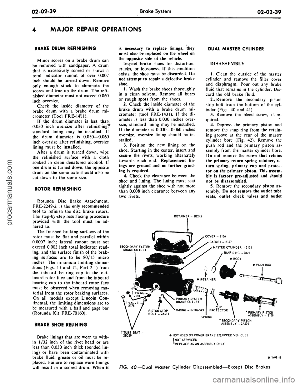
RETAINER - 2B245
DUAL MASTER CYLINDER
DISASSEMBLY
1.
Clean the outside of the master
cylinder and remove the filler cover
and diaphragm. Pour out any brake
fluid that remains in the cylinder. Dis-
card the old brake fluid.
2.*
Remove the secondary piston
stop bolt from the bottom of the cyl-
inder (Figs. 40 and 41).
3.
Remove the bleed screw, iL re-
quired.
4.
Depress the primary piston and
remove the snap ring from the retain-
ing groove at the rear of the master
cylinder bore (Fig. 42). Remove the
push rod and the primary piston as-
sembly from the master cylinder bore.
Do not remove the screw that retains
the primary return spring retainer, re-
turn spring, primary cup and protec-
tor on the primary piston. This assem-
bly is factory pre-adjusted and should
not be disassembled.
5.
Remove the secondary piston as-
sembly. Do not remove the outlet tube
seats,
outlet check valves and outlet
SECONDARY SYSTEM
BRAKE OUTLET
COVER -2166
GASKET-2167
MASTER CYLINDER -2155
SNAP RING -7821
BOOT
PUSH ROD
PRIMARY PISTON
ASSEMBLY - 2169
tTUBE SEAT-
2B220
* SECONDARY PISTON
ASSEMBLY - 2A502
• NOT USED ON POWER BRAKE EQUIPPED VEHICLES
fNOT SERVICED
•REPLACE AS AN ASSEMBLY ONLY
H 1499-B
FIG. 40— Dual Master Cylinder Disassembled—Except Disc Brakesprocarmanuals.com
Page 61 of 413
02-02-42
Brake System
02-02-42
CALIPER
ABUTMENTS
OUTBOARD
CALIPER HOUSING
DUST
BOOT RETAINING GROOVE
DUST
BOOT (4)
PISTON
SEAL (4)
EXTERNAL
TRANSFER
TUBE
SCREW
INBOARD
CALIPER HOUSING
FLEXIBLE
HOSE-^
H1367-C
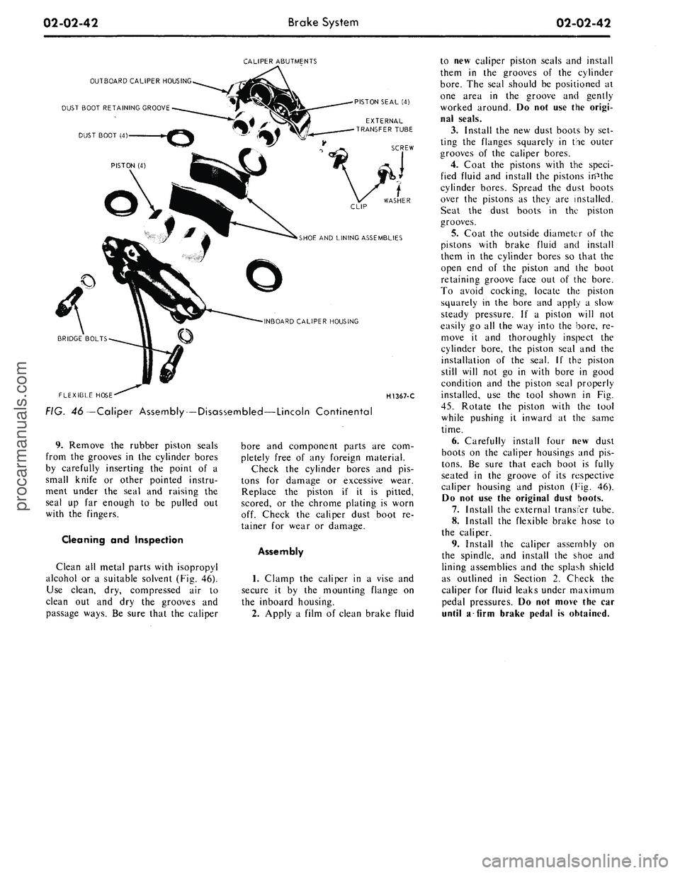
FIG. 46—Caliper Assembly — Disassembled—Lincoln Continental
9. Remove the rubber piston seals
from the grooves in the cylinder bores
by carefully inserting the point of a
small knife or other pointed instru-
ment under the seal and raising the
seal up far enough to be pulled out
with the fingers.
Cleaning and Inspection
Clean all metal parts with isopropyl
alcohol or a suitable solvent (Fig. 46).
Use clean, dry, compressed air to
clean out and dry the grooves and
passage ways. Be sure that the caliper
bore and component parts are com-
pletely free of any foreign material.
Check the cylinder bores and pis-
tons for damage or excessive wear.
Replace the piston if it is pitted,
scored, or the chrome plating is worn
off. Check the caliper dust boot re-
tainer for wear or damage.
Assembly
1.
Clamp the caliper in a vise and
secure it by the mounting flange on
the inboard housing.
2.
Apply a film of clean brake fluid
to new caliper piston seals and install
them in the grooves of the cylinder
bore.
The seal should be positioned at
one area in the groove and gently
worked around. Do not use the origi-
nal seals.
3.
Install the new dust boots by set-
ting the flanges squarely in the outer
grooves of the caliper bores.
4.
Coat the pistons with the speci-
fied fluid and install the pistons inPthe
cylinder bores. Spread the dust boots
over the pistons as they are installed.
Seat the dust boots in the piston
grooves.
5.
Coat the outside diameter of the
pistons with brake fluid and install
them in the cylinder bores so that the
open end of the piston and ihe boot
retaining groove face out of the bore.
To avoid cocking, locate the piston
squarely in the bore and apply a slow
steady pressure. If a piston will not
easily go all the way into the bore, re-
move it and thoroughly inspect the
cylinder bore, the piston seal and the
installation of the seal. If the piston
still will not go in with bore in good
condition and the piston seal properly
installed, use the tool shown in Fig.
45.
Rotate the piston with the tool
while pushing it inward at the same
time.
6. Carefully install four new dust
boots on the caliper housings and pis-
tons.
Be sure that each boot is fully
seated in the groove of its respective
caliper housing and piston (Fig. 46).
Do not use the original dust boots.
7.
Install the external transfer tube.
8. Install the flexible brake hose to
the caliper.
9. Install the caliper assembly on
the spindle, and install the shoe and
lining assemblies and the splash shield
as outlined in Section 2. Check the
caliper for fluid leaks under maximum
pedal pressures. Do not move the car
until a firm brake pedal is obtained.procarmanuals.com
Page 67 of 413
03-01-02
Suspension — Steering, Wheels And Tires — General Service
03-01-02
1 TESTING
POWER STEERING-
PRELIMINARY TESTS
The following preliminary checks
should always be made before per-
forming any operations.
AIR BLEEDING
Air in the power steering system
(shown by bubbles in the fluid) should
be bled. After making sure that the
reservoir is filled to specification (the
fluid must be at normal operating
temperature when the check is made),
turn the steering wheel through its full
travel three or four times. Do not hold
the wheels against their stops. Re-
check the fluid level.
CHECK FLUID LEVEL
Run the engine until the fluid is at
normal operating temperature. Then
turn the steering wheel all the way to
the left and right several times, and
shut off the engine.
Check the fluid level in the power
steering reservoir. The level must show
on the cross hatching between the bot-
tom of the dipstick and the full mark
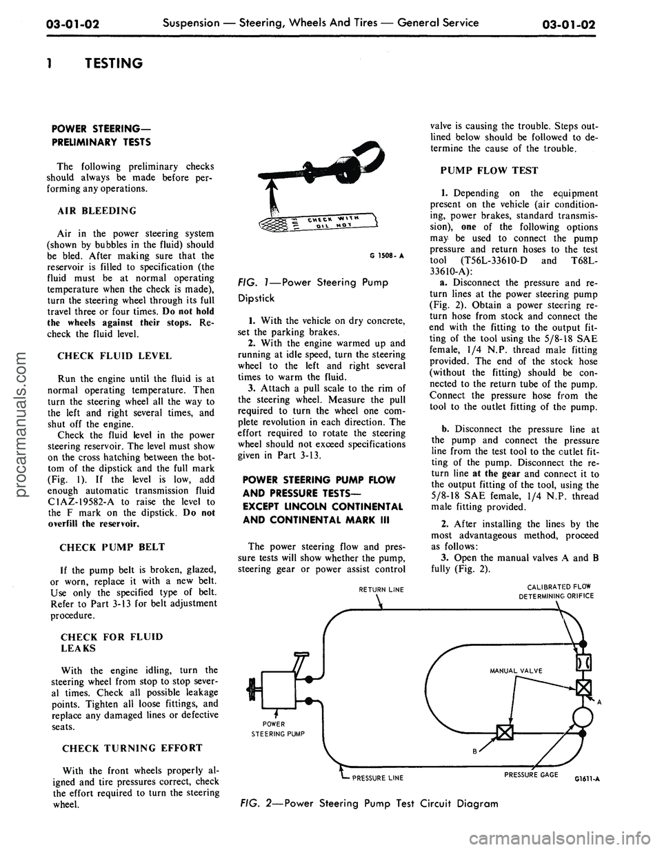
(Fig. 1). If the level is low, add
enough automatic transmission fluid
C1AZ-19582-A to raise the level to
the F mark on the dipstick. Do not
overfill the reservoir.
CHECK PUMP BELT
If the pump belt is broken, glazed,
or worn, replace it with a new belt.
Use only the specified type of belt.
Refer to Part 3-13 for belt adjustment
procedure.
CHECK FOR FLUID
LEAKS
With the engine idling, turn the
steering wheel from stop to stop sever-
al times. Check all possible leakage
points. Tighten all loose fittings, and
replace any damaged lines or defective
seats.
CHECK TURNING EFFORT
With the front wheels properly al-
igned and tire pressures correct, check
the effort required to turn the steering
wheel.
G 1508- A
FIG.
1—Power
Steering Pump
Dipstick
1.
With the vehicle on dry concrete,
set the parking brakes.
2.
With the engine warmed up and
running at idle speed, turn the steering
wheel to the left and right several
times to warm the fluid.
3.
Attach a pull scale to the rim of
the steering wheel. Measure the pull
required to turn the wheel one com-
plete revolution in each direction. The
effort required to rotate the steering
wheel should not exceed specifications
given in Part 3-13.
POWER STEERING PUMP FLOW
AND PRESSURE TESTS—
EXCEPT LINCOLN CONTINENTAL
AND CONTINENTAL MARK III
The power steering flow and pres-
sure tests will show whether the pump,
steering gear or power assist control
RETURN LINE
POWER
STEERING PUMP
Sr
valve is causing the trouble. Steps out-
lined below should be followed to de-
termine the cause of the trouble.
PUMP FLOW TEST
1.
Depending on the equipment
present on the vehicle (air condition-
ing, power brakes, standard transmis-
sion),
one of the following options
may be used to connect the pump
pressure and return hoses to the test
tool (T56L-3361O-D and T68L-
33610-A):
a. Disconnect the pressure and re-
turn lines at the power steering pump
(Fig. 2). Obtain a power steering re-
turn hose from stock and connect the
end with the fitting to the output fit-
ting of the tool using the
5/8-18
SAE
female, 1/4 N.P. thread male fitting
provided. The end of the stock hose
(without the fitting) should be con-
nected to the return tube of the pump.
Connect the pressure hose from the
tool to the outlet fitting of the pump.
b.
Disconnect the pressure line at
the pump and connect the pressure
line from the test tool to the outlet fit-
ting of the pump. Disconnect the re-
turn line at the gear and connect it to
the output fitting of the tool, using the
5/8-18
SAE female, 1/4 N.P. thread
male fitting provided.
2.
After installing the lines by the
most advantageous method, proceed
as follows:
3.
Open the manual valves A and B
fully (Fig. 2).
CALIBRATED FLOW
DETERMINING ORIFICE
PRESSURE LINE
FIG. 2—Power Steering Pump Test Circuit Diagram
PRESSURE GAGE
G1611-Aprocarmanuals.com
Page 70 of 413
03-01-05
Suspension — Steering, Wheels And Tires — General Service
03-01-05
type of equipment is used, follow the
installation and inspection instructions
provided by the equipment manufactu-
rer.
CASTER
Check the caster angle at each front
wheel.
The caster is the forward or rear-
ward tilt of the top of the wheel
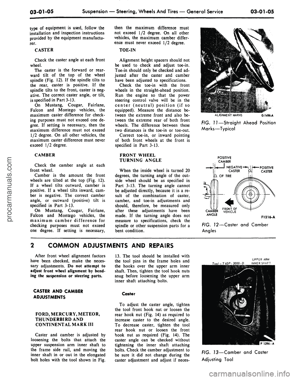
spindle (Fig. 12). If the spindle tilts to
the rear, caster is positive. If the
spindle tilts to the front, caster is neg-
ative. The correct caster angle, or tilt,
is specified in Part 3-13.
On Mustang, Cougar, Fairlane,
Falcon and Montego vehicles, the
maximum caster difference for check-
ing purposes must not exceed one de-
gree.
If setting is necessary, then the
maximum difference must not exceed
1/2 degree. On all other vehicles, the
maximum caster difference must never
exceed 1/2 degree.
CAMBER
Check the camber angle at each
front wheel.
Camber is the amount the front
wheels are tilted at the top (Fig. 12).
If a wheel tilts outward, camber is
positive. If a wheel tilts inward, cam-
ber is negative. The correct camber
angle, or outward (positive) tilt is
specified in Part 3-13.
On Mustang, Cougar, Fairlane,
Falcon and Montego vehicles, the
maximum camber difference for
checking purposes must not exceed
one degree. If setting is necessary,
then the maximum difference must
not exceed 1/2 degree. On all other
vehicles, the maximum camber differ-
ence must never exceed 1/2 degree.
TOE-IN
Alignment height spacers should not
be used to check and adjust toe-in.
Toe-in should only be checked and ad-
justed after the caster and camber
have been adjusted to specifications.
Check the toe-in with the front
wheels in the straight-ahead position.
Run the engine so that the power
steering control valve will be in the
center (neutral) position (if so
equipped). Measure the distance be-
tween the extreme front and also be-
tween the extreme rear of both front
wheels. The difference between these
two distances is the toe-in or toe-out.
Correct toe-in, or inward pointing
of both front wheels at the front is
specified in Part 3-13.
FRONT WHEEL
TURNING ANGLE
When the inside wheel is turned 20
degrees, the turning angle of the out-
side wheel should be as specified in
Part 3-13. The turning angle cannot
be adjusted directly, because it is a re-
sult of the combination of caster,
camber, and toe-in adjustments and
should, therefore, be measured only
after these adjustments have been
made. If the turning angle does not
measure to specifications, check the
spindle or other suspension parts for a
bent condition.
ALIGNMENT
MARKS
G-1496-A
FIG. I?—Straight Ahead Position
Marks—Typical
POSITIVE
CAMBER
• •
NEGATIVE-*!
| ^*—
CASTER
ICL
OF TIRE
POSITIVE
CASTER
5r\
CA&U
ANGlE
F1216-A
FIG. 72—Caster and Camber
Angles
COMMON ADJUSTMENTS AND REPAIRS
After front wheel alignment factors
have been checked, make the neces-
sary adjustments. Do not attempt to
adjust front wheel alignment by bend-
ing the suspension or steering parts.
CASTER AND CAMBER
ADJUSTMENTS
FORD, MERCURY, METEOR,
THUNDERBIRDAND
CONTINENTAL MARK III
Caster and camber is adjusted by
loosening the bolts that attach the
upper suspension arm inner shaft to
the frame side rail, and moving the
inner shaft in or out in the elongated
bolt holes with the tool shown in Fig.
13.
The tool should be installed with
the tool pins in the frame holes and
the hooks over the upper arm inner
shaft. Then, tighten the tool hook nuts
snug before loosening the upper arm
inner shaft attaching bolts.
Caster
To adjust the caster angle, tighten
the tool front hook nut or loosen the
rear hook nut (Fig. 14) as required to
increase caster to the desired angle.
To decrease caster, tighten the tool
rear hook nut or loosen the front
hook nut as required (Fig. 14). The
caster angle can be checked without
tightening the inner shaft attaching
bolts.
Check the camber adjustment to
be sure it did not change during the
caster adjustment and adjust if neces-
FIG. 73—Camber and Caster
Adjusting Toolprocarmanuals.com
Page 73 of 413
03-01-08
Suspension
—
Steering,
Wheels
And
Tires
—
General Service
03-01-08
3.
Remove the lower (upper on
Mustang and Cougar) cover- to-
housing attaching bolt.
4.
With a clean punch or like in-
strument, clean out or push inward
the loose lubricant in the filler plug
hole and cover to housing attaching
bolt hole.
5.
Slowly turn the steering wheel to
the left stop, lubricant should rise
within the lower cover bolt hole; then
slowly turn the steering wheel to the
right stop, lubricant should rise within
the filler plug hole. If lubricant does
not rise in both the cover bolt hole
and the filler plug hole, add lubricant
until it comes out both holes during
this check.
6. Install the lower (upper on
Mustang and Cougar) cover- to-
housing attaching bolt and the filler
plug.
CLEANING
AND
INSPECTION
FRONT
END
GENERAL
INSPECTION
Do not check and adjust front
wheel alignment without first making
the following inspection for front-end
damage, or wear.
1.
Check for specified air pressures
in all four tires.
2.
Raise the front of the vehicle off
the floor. Shake each front wheel
grasping the upper and lower surfaces
of the tire. Check the front suspension
ball joints and mountings for loose-
ness,
wear, and damage. Check the
brake backing plate mountings. Tor-
que all loose nuts and bolts to specifi-
cation. Replace all worn parts as out-
lined in Part 3-2.
3.
Check the steering gear mount-
ings and all steering linkage connec-
tions for looseness. Torque all mount-
ings to specifications. If any of the
linkage is worn or bent, replace the
parts as outlined in Part 3-5.
4.
Check the front wheel bearings.
If any in-and-out free play is noticed,
adjust the bearings to specifications.
Replace worn or damaged bearings as
outlined in Part 3-12.
5.
Spin each front wheel with a
wheel spinner, and check and balance
each wheel as required.
6. Check the action of the shock
absorbers. If the shock absorbers are
not in good condition, the vehicle may
not settle in a normal, level position,
and front wheel alignment may be af-
fected.
WHEEL INSPECTION
Wheel hub nuts should be inspected
and tightened to specification at pre-
delivery. Loose wheel hub nuts may
cause shimmy and vibration. Elongat-
ed stud holes in the wheels may also
result from loose hub nuts.
Keep the wheels and hubs clean.
Stones wedged between the wheel and
drum and lumps of mud or grease can
unbalance a wheel and tire.
Check for damage that would affect
the runout of the wheels. Wobble or
shimmy caused by a damaged wheel
will eventually damage the wheel bear-
ings.
Inspect the wheel rims for dents
that could permit air to leak from the
tires.
UPPER BALL JOINT
INSPECTION
Ford,
Mercury,
Meteor,
Thunderbird,
Lincoln Continental
and
Continental Mark
III
1.
Raise the vehicle and place floor
jacks beneath the lower arms.
2.
Ask an assistant to grasp the
lower edge of the tire and move the
wheel in and out.
3.
As the wheel is being moved in
and out, observe the upper end of the
spindle and the upper arm.
4.
Any movement between the
upper end of the spindle and the upper
arm indicates ball joint wear and loss
of preload. If any such movement is
observed, replace the upper ball joint.
During
the
foregoing
check,
the
lower ball joint will
be
unloaded
and
may
move.
Disregard
all
such
move-
ment
of the
lower ball
joint.
Also,
do
not mistake loose wheel bearings
for a
worn ball
joint.
Cougar,
Fairlane,
Falcon,
Montego
and
Mustang
1.
Raise the vehicle on a frame
contact hoist or by floor jacks placed
beneath the underbody until the wheel
falls to the full down position as
shown in Fig. 18. This will unload the
upper ball joint.
2.
Adjust the wheel bearings as de-
scribed in Part 3-12.
3.
Attach a dial indicator to the
upper arm and position the indicator
so that the plunger rests against the
inner side of the wheel rim adjacent to
the upper arm ball joint.
4.
Grasp the tire at the top and
bottom, and slowly move the tire in
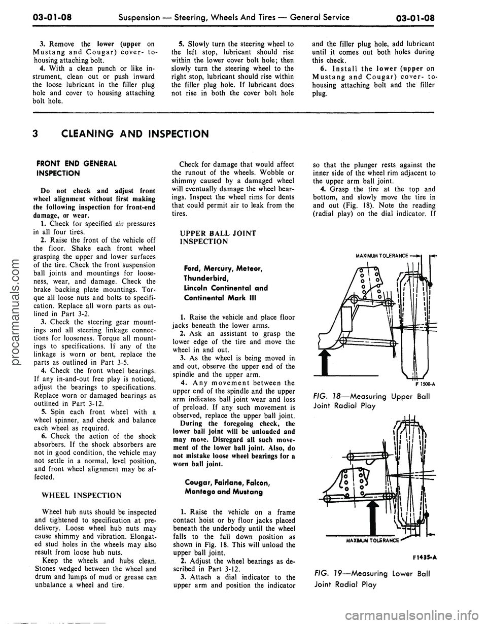
and out (Fig. 18). Note the reading
(radial play) on the dial indicator. If
MAXIMUM TOLERANCE
F
1500-A
FIG.
T8—Measuring Upper Ball
Joint Radial Play
MAXIMUM TOLERANCE
F14
35-A
FIG.
79—Measuring Lower Ball
Joint Radial Playprocarmanuals.com
Page 75 of 413
03-01-10
Suspension — Steering, Wheels And Tires — General Service
03-01-10
The following procedure should be
followed when cleaning the relief valve
which is a part of the pump valve as-
sembly.
1.
Using a punch or rod of suitable
diameter, apply an even pressure in a
straight line to the tip of the relief
valve pin (Fig. 20). Depress the valve
two or three times to exhaust the oil
which is trapped in the assembly. Do
not hammer on the valve pin or hous-
ing.
2.
Submerge the assembly in a con-
tainer of clean solvent. Again applying
an even pressure to the tip of the relief
valve pin, (a sudden strong force could
push the pin through the relief valve
spool) move the valve in and out sev-
eral times, thereby thoroughly flushing
the assembly. Pressure created within
the valve bore when the valve is moved
inward should force the cleaning fluid
out through the sensing orifice. If this
does not occur, the sensing orifice
should be cleaned with a piece of wire.
The valve must move freely and even-
ly. If the pin is bent or damaged, or if
the valve binds, the pump valve must
be replaced.
INSPECTION
The following describes the compo-
nents of the power steering pump
which must be replaced regardless of
condition and how to determine when
other components should be replaced.
The outlet fitting hex nut may be
reused if the corners of the hex are
not rounded. The housing bolts may
be reused if the threads are not dam-
aged.
All gaskets and seals must be re-
placed with new components except
the rotor shaft seal which should be
reused unless it was leaking.
The reservoir assembly may be
reused if the reservoir seal and gasket
areas are not damaged (dents, scratch-
es,
etc.). The soldered joints of the re-
turn and fill tubes must not be loose
or bent. Be sure to check for a broken
baffle.
The housing or housing assembly
may be reused if there is no damage
(scratches, etc.) at reservoir gasket,
outlet fitting or cover seal areas.
If the outlet fitting is damaged, the
pump housing must be replaced. The
pressure plate springs may be reused
providing they are not bent, broken or
have not taken a set.
Do not reuse the retainer end plate
if it is burred or damaged. The upper
pressure plate may be reused if there
is no scoring on the wear surface. It is
acceptable to polish the phosphate
coating.
The rotor and cam assembly can be
reused if there is no wear other than
the removal of the phosphate coating
on the cam contour. Do not disas-
semble the rotor and cam assembly.
Push the rotor part way out the cam
insert taking care not to let the slip-
pers and springs fall out. Check the
cam ID for scoring and burning.
Check the rotor faces and OD for
scoring and chipping. Do not attempt
to repair or refinish the lower and
upper pressure plates, cam or rotor
assembly. When wear or burning is
encountered, replace, them with new
components.
Install a new rotor and cam assem-
bly if the slippers are worn. Replace
the springs if they are bent or broken.
Polishing the phosphate coating of the
slipper sealing surface is permissable.
The rotor shaft can be reused if the
front and rear thrust faces, the bush-
ing diameter and the shaft seal diame-
ter are not excessively worn or scored.
The housing plate and bushing as-
sembly may be reused if all of the
threaded holes are not damaged
beyond repair and the bushing diame-
ter is not scored or worn .0005 inch
over the maximum dimension of .6897
inch. Threaded holes can be repaired
by drilling out the damaged threads
and installing a helicoil insert. If the
bushing is scored or excessively worn,
a new plate and bushing assembly
must be installed.
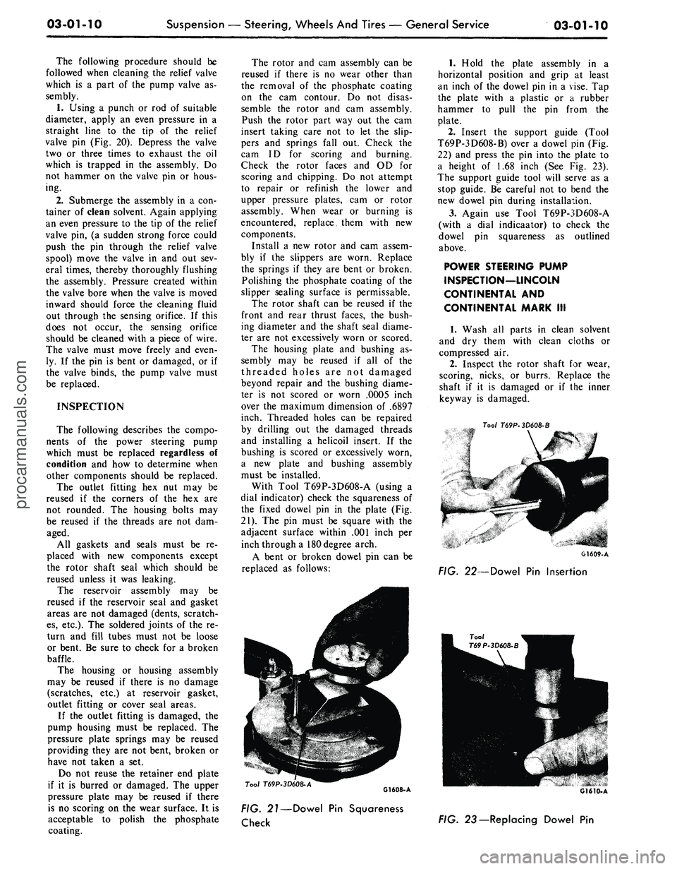
With Tool T69P-3D608-A (using a
dial indicator) check the squareness of
the fixed dowel pin in the plate (Fig.
21).
The pin must be square with the
adjacent surface within .001 inch per
inch through a 180 degree arch.
A bent or broken dowel pin can be
replaced as follows:
1.
Hold the plate assembly in a
horizontal position and grip at least
an inch of the dowel pin in a vise. Tap
the plate with a plastic or a rubber
hammer to pull the pin from the
plate.
2.
Insert the support guide (Tool
T69P-3D608-B) over a dowel pin (Fig.
22) and press the pin into the plate to
a height of 1.68 inch (See Fig. 23).
The support guide tool will serve as a
stop guide. Be careful not to bend the
new dowel pin during installation.
3.
Again use Tool T69P-3D608-A
(with a dial indicaator) to check the
dowel pin squareness as outlined
above.
POWER STEERING PUMP
INSPECTION—LINCOLN
CONTINENTAL AND
CONTINENTAL MARK III
1.
Wash all parts in clean solvent
and dry them with clean cloths or
compressed air.
2.
Inspect the rotor shaft for wear,
scoring, nicks, or burrs. Replace the
shaft if it is damaged or if the inner
keyway is damaged.
Tool
T69P-3D608-B
G1609-A
FIG. 22—Dowel Pin Insertion
Tool
T69P-3D608-A
G1608-A
FIG. 21—Dowel Pin Squareness
Check
FIG. 23 — Replacing Dowel Pinprocarmanuals.com
Page 76 of 413
03-01-11
Suspension — Steering, Wheels And Tires — General Service
03-01-11
3.
Inspect the rotor, rollers, cam
ring, pressure plate, cover, and bush-
ing in the pressure plate for wear or
scoring. If damaged, replacement of
the pump (less housing) is required.
4.
Make sure the inner faces of the
cover and the housing are free of
paint, nicks, or burrs. Check all fluid
passages for restrictions.
5.
Inspect the valving surfaces
(areas where the rotor and rollers con-
tact) for wear or scoring. Replace the
pressure plate or the cover if worn or
scored. Inspect the bushing in the
pressure plate for wear or scoring, and
replace the plate if necessary.
6. Inspect the control valve for
scores, nicks, or burred edges. Re-
place the valve if damaged. Do not dis-
assemble the valve. Check the valve
for free movement in the housing
bore.
7.
Inspect the tube seat in the hous-
ing. If damaged, remove it with an
E-Z-Out and install a new seat.
SHOCK ABSORBER CHECKS
All vehicles are equipped with hy-
draulic shock absorbers of the direct-
acting type and are nonadjustable and
nonrefillable. They cannot be repaired.
Before replacing a shock absorber,
check the action of the shock absor-
bers as follows:
ON VEHICLE TESTS
1.
Check the shock absorber to be
sure it is securely and properly in-
stalled. Check the shock absorber in-
sulators for damage and wear.
Replace any defective insulators and
tighten attachments to the specified
torque (on a shock absorber which in-
corporates integral insulators, replace
the shock absorbers).
2.
Inspect the shock absorber for
evidence of fluid leakage. A light film
of fluid is permissible. Be sure any
fluid observed is not from sources
other than the shock absorber.
Replace the shock absorber if leak-
age is severe.
3.
Disconnect the lower end of the
shock absorber. Extend and compress
the shock absorber as fast as possible,
using as much travel as possible.
Action should become smooth and
uniform throughout each stroke.
Higher resistance on extension than
on compression is a normal condition.
Faint swish noises are also normal.
Remove the shock absorber for a
bench test if action is erratic. If the
action is smooth, but the shock absor-
bers are suspected of being weak fol-
low step 4:
4.
Repeat step 3 on the mating
shock absorber installed on the oppo-
site side of the vehicle, and compare
results of both tests. If the action is
similar, it is unlikely that either shock
absorber is defective. Reconnect both
shock absorbers.
Replace the shock absorber having
the lower resistance. Ensure that the
part number of the replacement is the
same as that of the original shock ab-
sorber. The replacement shock absor-
ber resistance will appear to be higher
than either original due to initial fric-
tion of the rod seal.
BENCH TEST
With the shock absorber right side
up (as installed in vehicle), extend it
fully. Then turn the shock absorber
upside down and fully compress it.
Repeat this procedure at least three
times to ensure that any entrapped air
has been expelled. Now place the
shock absorber right side up in a vise,
and hand stroke the shock absorber as
described in On Vehicle Tests, step 3.
If action is not now smooth and uni-
form, install a new shock absorber.procarmanuals.com