horn FORD MUSTANG 1969 Volume One Chassis
[x] Cancel search | Manufacturer: FORD, Model Year: 1969, Model line: MUSTANG, Model: FORD MUSTANG 1969Pages: 413, PDF Size: 75.81 MB
Page 115 of 413

03-05-02
Steering Columns
And
Linkage
03-05-02
which also will shear away during
im-
pact.
TILT STEERING COLUMNS
The steering column
is of the col-
lapsible type
to
lessen
the
possibility
of injury
to the
driver
of the
vehicle
should
he
become involved
in an
acci-
dent.
The
lower
end of the
steering
column tube
at the
bellows area will
collapse approximately
six
inches
upon
a
hard impact.
The shift tube
and the
steering shaft
are provided with plastic dowels
and
will shear
and
allow them
to
collapse
in proportion
to the
outer tube upon
impact.
Once
the
steering column
has
been
collapsed,
a
complete
new
column
must
be
installed.
The tilt column features nine driv-
ing positions (four
up and
four down
from
a
center position).
The
.column
also features
a
turn signal switch with
a lane-changer position turn indicating
position
and
emergency warning flash-
er control.
TILT-AWAY STEERING COLUMNS
The tilt-away steering column
fea-
tures nine driving positions (four
up
and four down from
a
center position)
and
a
tilt-away position that
is
auto-
matically accomplished
on
Mustang
and Cougar models when
the
ignition
key
is
turned
to the
OFF
position
and
the left door
is
opened.
On
Thunder-
bird models,
the
tilt-away occurs when
the shift lever
is
placed
in
PARK
and
the driverns door
is
opened.
The steering column
is of the col-
lapsible type
to
lessen
the
possibility
of injury
to the
driver
of the
vehicle
should
he
become involved
in an
acci-
dent.
The
lower
end of the
steering
column tube
at the
bellows area will
collapse approximately
six
inches
upon
a
hard impact.
The shift tube
and the
steering shaft
are provided with plastic dowels
and
will shear
and
allow them
to
collapse
in proportion
to the
outer tube upon
impact.
Once
the
steering column
has
been
collapsed,
a
complete
new
column
must
be
installed along with mounting
brackets which will also shear away
during impact.
IN-VEHICLE ADJUSTMENTS
AND
REPAIRS
STEERING WHEEL SPOKE
POSITION ADJUSTMENT
When
the
steering gear
is on the
high point,
the
front wheels should
be
in
the
straight-ahead position
and the
steering wheel spokes should
be in
their normal position with
the
Pitman
arm pointing directly forward.
If the
spokes
are not in
their normal posi-
tion, they
can be
adjusted without
dis-
turbing
the
toe-in adjustment (Part
3-1).
STEERING WHEEL
REPLACEMENT
1.
Disconnect
the
negative cable
from
the
battery.
2.
Working from
the
underside
of
the steering wheel spoke, remove
the
crash
pad
attaching screws. Lift
the
crash
pad
from
the
wheel.
(On
Conti-
nental Mark
III
models,
pry out the
crash
pad
insert
and
remove
the two
screws that secure
the
crash
pad. Re-
move
the
crash
pad. On
models
equipped with steering wheel mounted
speed controls, refer
to
Group
16 for
removal instructions). Remove
the
horn ring
(if so
equipped)
by
turning
it counterclockwise.
3.
Remove
the
steering wheel
nut,
and then remove
the
steering wheel
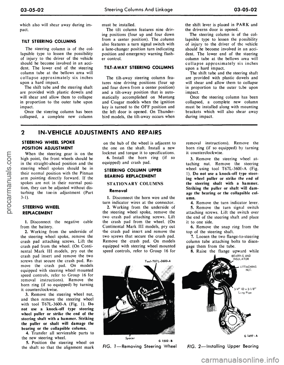
with tool T67L-3600-A
(Fig. 1). Do
not
use a
knock-off type steering
wheel puller
or
strike
the end of the
steering shaft with
a
hammer. Striking
the puller
or
shaft will damage
the
bearing
or the
collapsible column.
4.
Transfer
all
serviceable parts
to
the
new
steering wheel.
5.
Position
the
steering wheel
on
the shaft
so
that
the
alignment mark
on
the hub of the
wheel
is
adjacent
to
the
one on the
shaft. Install
a new
locknut
and
torque
it to
specifications.
6. Install
the
horn ring
(if so
equipped)
and
crash
pad.
STEERING COLUMN UPPER
BEARING REPLACEMENT
STATIONARY COLUMNS
Removal
1. Disconnect
the
horn wire
and the
turn indicator wires
at the
connector.
2.
Working from
the
underside
of
the steering wheel spoke, remove
the
two crash
pad
attaching screws. Lift
the crash
pad
from
the
wheel.
(On
Continental Mark
III
models,
pry out
the crash
pad
insert
and
remove
the
two screws that secure
the
crash
pad.
Remove
the
crash
pad. On
models
equipped with steering wheel mounted
speed controls, refer
to
Group
16 for
7oo/-T67L-3600-A
removal instructions). Remove
the
horn ring
(if so
equipped)
by
turning
it counterclockwise.
3.
Remove
the
steering wheel
at-
taching
nut.
Remove
the
steering
wheel using tool T67L-3600-A
(Fig.
1).
Do not use a
knock-off type steer-
ing wheel puller
or
strike
the end of
the steering shaft with
a
hammer.
Striking
the
puller
or
shaft will
dam-
age
the
bearing
or the
collapsible
col-
umn.
4.
Remove
the
turn indicator lever.
5.
Remove
the
turn signal switch
attaching screws. Lift
the
switch over
the
end of the
steering shaft
and
place
it
to one
side.
6. Remove
the
snap ring from
the
top
of the
steering shaft.
7.
Loosen
the two
flange-to-steering
column tube attaching bolts
to
disen-
gage them from
the
tube.
8. Raise
the
flange upward while
BEARING
AND
INSULATOR
Spacer
G 1502 -B
FIG.
1—Removing
Steering Wheel
G 1497-A
FIG. 2—Installing Upper Bearingprocarmanuals.com
Page 116 of 413

03-05-03
Steering Columns And Linkage
03-05-03
tapping the steering shaft lightly with
a plastic hammer to free the bearing
and flange from the shaft.
9. Remove the bearing and insula-
tor from the flange.
Installation
1.
Install flange bolts (square head)
in flange if they were removed. Turn
the nuts onto the bolts one complete
turn only.
2.
Position the flange onto the
steering column tube.
3.
Engage the two flange bolt heads
with the square holes in the column
tube,
then tighten the two attaching
nuts to specification.
4.
Position the bearing and insula-
tor on the shaft. Work it down onto
the shaft as far as possible, then place
a piece of 3/4 ID x 2 1/8 inch pipe
over the end of the shaft and install
the steering wheel attaching nut (Fig.
2).
5.
Tighten the nut until the bearing
is seated in the flange, then remove
the nut and pipe from the shaft.
6. Position the turn signal switch
on the flange and install the three at-
taching screws.
7.
Make certain that the wheels are
in the straight ahead position. Place
the steering wheel on the steering
shaft with the spokes in the horizontal
position. Install and torque the attach-
ing nut to specification.
8. Secure the crash pad to the
steering wheel with the two attaching
screws.
9. Connect the horn and turn signal
wires.
10.
Install the turn signal lever.
TILT WHEEL COLUMNS
Removal
1.
Disconnect the negative cable
from the battery.
2.
Remove the steering wheel with
tool T67L-3600-A (Fig. 1). Install the
spring, shipping spacer (3/4 x 1 1/8-
inch pipe) and a steering wheel attach-
ing nut on the shaft. Do not use a
knock-off type steering wheel puller or
strike the end of the steering shaft
with a hammer. Striking the puller or
shaft will damage the bearing or the
collapsible column.
3.
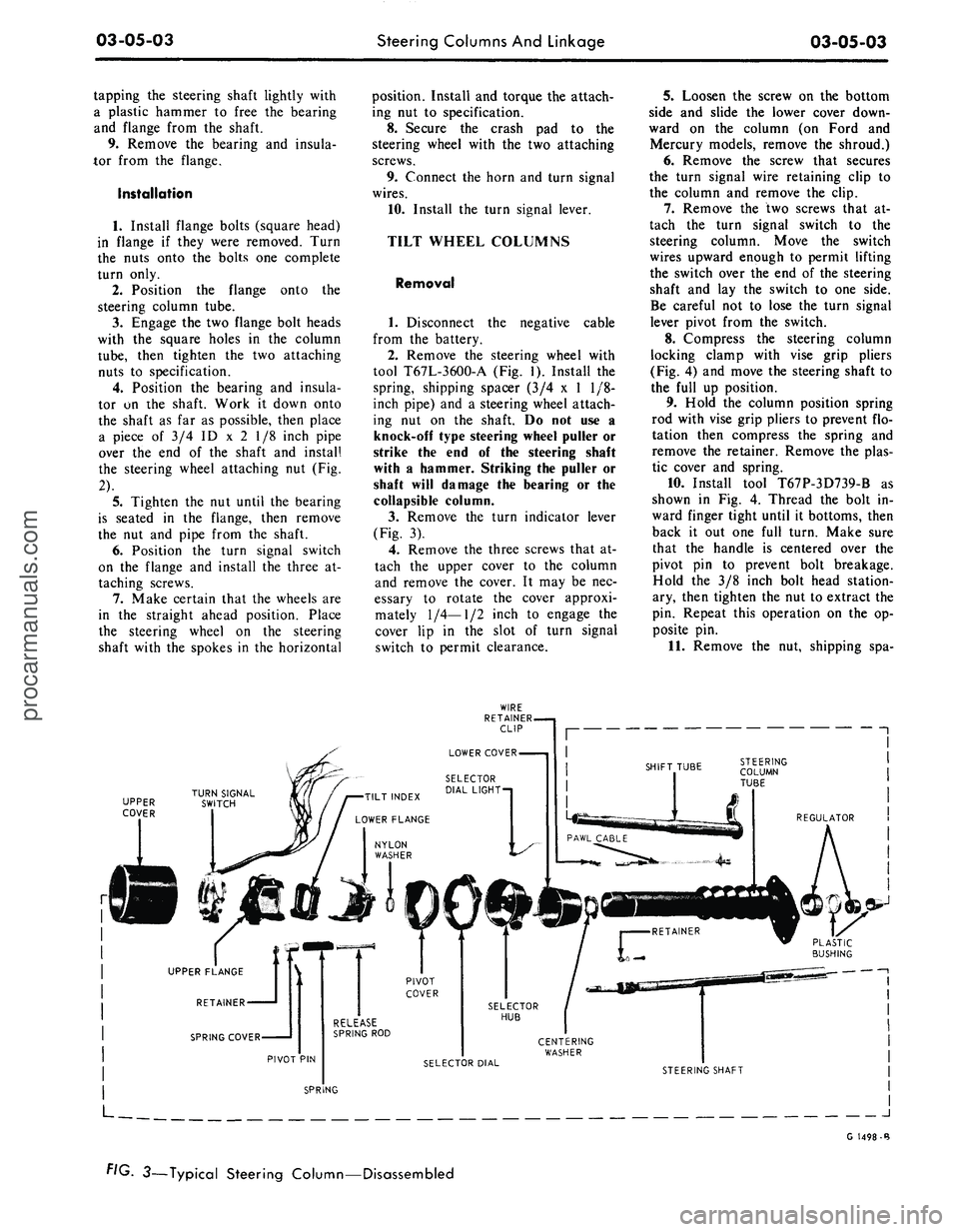
Remove the turn indicator lever
(Fig. 3).
4.
Remove the three screws that at-
tach the upper cover to the column
and remove the cover. It may be nec-
essary to rotate the cover approxi-
mately
1/4—1/2
inch to engage the
cover lip in the slot of turn signal
switch to permit clearance.
5.
Loosen the screw on the bottom
side and slide the lower cover down-
ward on the column (on Ford and
Mercury models, remove the shroud.)
6. Remove the screw that secures
the turn signal wire retaining clip to
the column and remove the clip.
7.
Remove the two screws that at-
tach the turn signal switch to the
steering column. Move the switch
wires upward enough to permit lifting
the switch over the end of the steering
shaft and lay the switch to one side.
Be careful not to lose the turn signal
lever pivot from the switch.
8. Compress the steering column
locking clamp with vise grip pliers
(Fig. 4) and move the steering shaft to
the full up position.
9. Hold the column position spring
rod with vise grip pliers to prevent flo-
tation then compress the spring and
remove the retainer. Remove the plas-
tic cover and spring.
10.
Install tool T67P-3D739-B as
shown in Fig. 4. Thread the bolt in-
ward finger tight until it bottoms, then
back it out one full turn. Make sure
that the handle is centered over the
pivot pin to prevent bolt breakage.
Hold the 3/8 inch bolt head station-
ary, then tighten the nut to extract the
pin. Repeat this operation on the op-
posite pin.
11.
Remove the nut, shipping spa-
UPPER
COVER
J
G 1498-B
FIG. 3—Typical Steering Column—Disassembledprocarmanuals.com