idler arm center link FORD MUSTANG 1969 Volume One Chassis
[x] Cancel search | Manufacturer: FORD, Model Year: 1969, Model line: MUSTANG, Model: FORD MUSTANG 1969Pages: 413, PDF Size: 75.81 MB
Page 114 of 413
03-05-01
Steering Columns And Linkage
03-05-01
PART 3-5 Steering
Columns
and Linkage
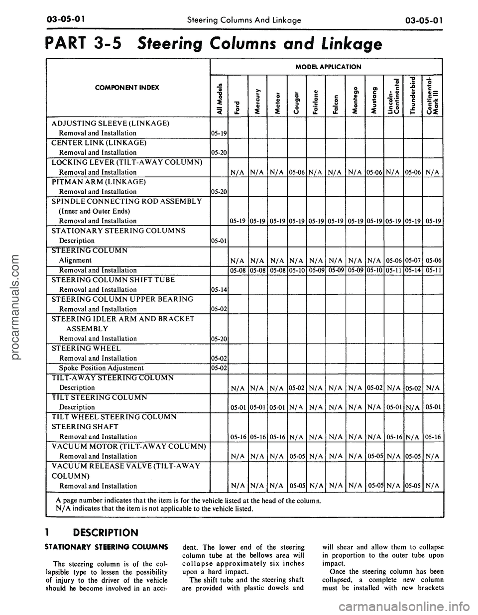
COMPONENT INDEX
ADJUSTING SLEEVE (LINKAGE)
Removal and Installation
CENTER LINK (LINKAGE)
Removal and Installation
LOCKING LEVER (TILT-AWAY COLUMN)
Removal and Installation
PITMAN ARM (LINKAGE)
Removal and Installation
SPINDLE CONNECTING ROD ASSEMBLY
(Inner and Outer Ends)
Removal and Installation
STATIONARY STEERING COLUMNS
Description
STEERING COLUMN
Alignment
Removal and Installation
STEERING COLUMN SHIFT TUBE
Removal and Installation
STEERING COLUMN UPPER BEARING
Removal and Installation
STEERING IDLER ARM AND BRACKET
ASSEMBLY
Removal and Installation
STEERING WHEEL
Removal and Installation
Spoke Position Adjustment
TILT-AWAY STEERING COLUMN
Description
TILT STEERING COLUMN
Description
TILT WHEEL STEERING COLUMN
STEERING SHAFT
Removal and Installation
VACUUM MOTOR (TILT-AWAY COLUMN)
Removal and Installation
VACUUM RELEASE VALVE (TILT-AWAY
COLUMN)
Removal and Installation
MODEL APPLICATION
All
Models
05-19
05-20
05-20
05-01
05-14
05-02
05-20
05-02
05-02
Ford
N/A
05-19
N/A
05-08
N/A
05-01
05-16
N/A
N/A
Mercury
N/A
05-19
N/A
05-08
N/A
05-01
05-16
N/A
N/A
Meteor
N/A
05-19
N/A
05-08
N/A
05-01
05-16
N/A
N/A
Cougar
05-06
05-19
N/A
05-10
05-02
N/A
N/A
05-05
05-05
Fairlane
N/A
05-19
N/A
05-09
N/A
N/A
N/A
N/A
N/A
Falcon
N/A
05-19
N/A
05-09
N/A
N/A
N/A
N/A
N/A
Montego
N/A
05-19
N/A
05-09
N/A
N/A
N/A
N/A
N/A
Mustang
05-06
05-19
N/A
05-10
05-02
N/A
N/A
05-05
05-05
Lincoln-
Continental
N/A
05-19
05-06
05-11
N/A
05-01
05-16
N/A
N/A
Thunderbird
05-06
05-19
05-07
05-14
05-02
N/A
N/A
05-05
05-05
Continental-
Mark
III
N/A
05-19
05-06
05-11
N/A
05-01
05-16
N/A
N/A
A page number indicates that the item is for the vehicle listed at the head of the column.
N/A indicates that the item is not applicable to the vehicle listed.
1 DESCRIPTION
STATIONARY STEERING COLUMNS
The steering column is of the col-
lapsible type to lessen the possibility
of injury to the driver of the vehicle
should he become involved in an acci-
dent. The lower end of the steering
column tube at the bellows area will
collapse approximately six inches
upon a hard impact.
The shift tube and the steering shaft
are provided with plastic dowels and
will shear and allow them to collapse
in proportion to the outer tube upon
impact.
Once the steering column has been
collapsed, a complete new column
must be installed with new brackets
procarmanuals.com
Page 133 of 413
03-05-20
Steering Columns And Linkage
03-05-20
placed if it becomes worn or damaged
(Figs.
18 through 21). Do not attempt
to straighten the sleeve if damaged.
1.
Remove the spindle connecting
rod end assemblies as described in the
previous sub-section.
2.
Screw the spindle rod end assem-
blies into the new sleeve the same
number of turns as the ends that were
removed. Do not tighten the clamp
bolts at this time.
3.
Position the sleeve and end as-
sembly on the center link and the
spindle arm. Install the attaching nut,
torque it to specification, and install
the cotter pin.
4.
Check and, if necessary, adjust
toe-in (Part 3-1). After toe-in is
checked and adjusted, oil the sleeve
clamp bolts then torque them to speci-
fication. The sleeve clamp must be in-
stalled as shown in Figs. 18 through
21.
CENTER LINK
REPLACEMENT
The center link connecting the Pit-
man arm and the idler arm is non-
adjustable and is provided with ta-
pered holes to accommodate the ball
studs (Figs. 18 through 21). The link
should be replaced when damaged or
when worn at the ball studs. On Lin-
coln Continental models, the link
should be replaced if excessive loose-
ness is noticed in either ball stud sock-
et.
REMOVAL
1.
Raise the vehicle on a hoist and
position safety stands.
2.
Remove the cotter pins and nuts
that attach both inner connecting rod
ends to the center link (Figs. 18
through 21).
3.
Disconnect the inner connecting
rod ends from the center link using
Tool 3290-C (Fig. 22).
4.
Remove the cotter pin and nut
attaching the idler arm to the center
link. Disconnect the idler arm from
the center link using Tool 3290-C for
Lincoln Continental models only.
5.
Remove the cotter pin and nut
attaching the Pitman arm to the cen-
ter link. Disconnect the Pitman arm
from the center link (use Tool 3290-C)
and remove the center link. On ve-
hicles equipped with the non-integral
power steering system, remove the
center link from the control valve as
detailed in Part 3-7.
INSTALLATION
1.
Replace the rubber seals on the
spindle connecting rod ends, if re-
quired.
2.
Position the center link to the
Pitman arm and idler arm and install
the attaching nuts loosely. On all ve-
hicles except Lincoln Continental
models, place the idler arm and the
front wheels in the straight ahead po-
sition to insure keeping the steering
wheel aligned and to prevent bushing
damage after the attaching nuts have
been torqued. On Lincoln Continental
models, insure that the seal is properly
installed on the center link. Torque
the nuts to the low end of the specifi-
cation. Continue to tighten each nut
until the slots in the nut align with the
hole in the stud. Then install a new
cotter pin.
3.
Position the spindle connecting
rod ends to the center link and install
the attaching nuts. Torque the nuts to
the low end of the specification. Con-
tinue to tighten each nut until the
slots in the nut align with the hole in
the stud. Then, install a new cotter
pin.
4.
Remove the safety stands, lower
the vehicle, check and adjust toe-in to
specification (Part 3-1).
STEERING IDLER ARM
AND BRACKET ASSEMBLY
REPLACEMENT
REMOVAL
If the idler arm bushings are worn
the complete idler arm assembly must
be replaced. In Lincoln Continental
models, if the socket at the idler
bracket is excessively loose, replace
the complet assembly.
1.
Remove the cotter pin and nut
attaching the steering center link at
the idler arm (Figs. 18 through 21).
2.
Disconnect the center link from
the idler arm (on Lincoln Continental
models, use Tool 3290-C).
3.
Remove the two bolts that attach
the idler arm and bracket assembly to
the frame.
INSTALLATION
1.
Secure the new idler arm and
bracket assembly to the frame with
the two attaching bolts (nuts and flat
washers as shown in Figs. 18, 19 and
21).
2.
On all vehicles except Lincoln
Continental models, place the idler
arm and the front wheels in the
straight ahead position to insure keep-
ing the steering wheel aligned and to
prevent bushing damage after the at-
taching nut has been torqued. Insert
the center link stud through the hole
in the end of the idler arm and install
the nut and washer.
On Lincoln Continental models, in-
sert the center link stud through the
hole in the end of the idler arm insur-
ing that the seal is properly installed
on the center link.
3.
Torque the idler arm rod nut to
specification and install a new cotter
pin.
PITMAN ARM
REPLACEMENT
REMOVAL
1.
Remove the cotter pin from the
castellated nut that attaches the steer-
ing center link to the Pitman arm.
Remove the castellated nut.
2.
Disconnect the steering center
link from the Pitman arm with tool
3290-C.
3.
Remove the Pitman arm attaching
nut and lock washer.
4.
Position the front wheels in the
straight ahead position. Remove the
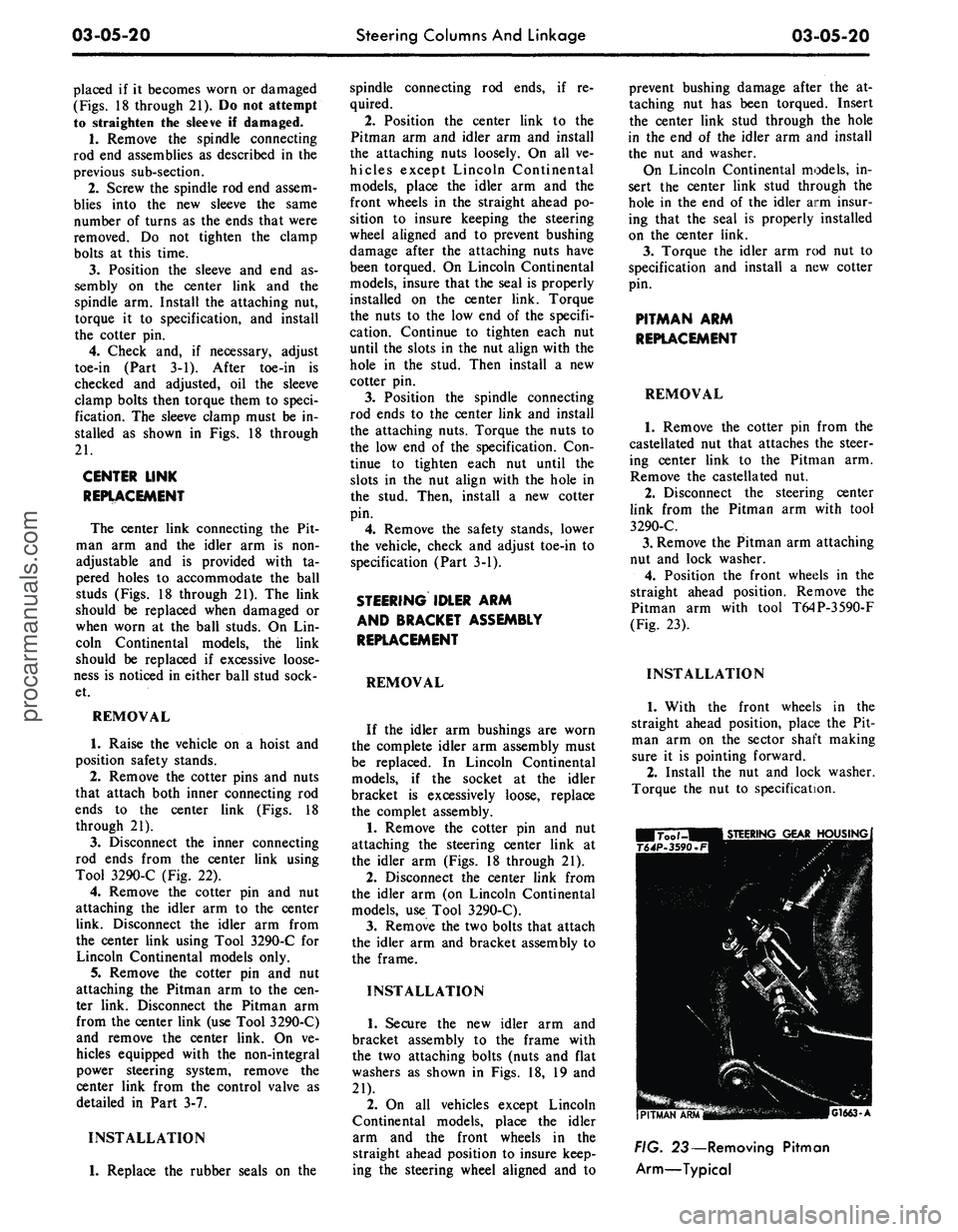
Pitman arm with tool T64P-3590-F
(Fig. 23).
INSTALLATION
1.
With the front wheels in the
straight ahead position, place the Pit-
man arm on the sector shaft making
sure it is pointing forward.
2.
Install the nut and lock washer.
Torque the nut to specification.
G1663-A
FIG. 23— Removing Pitman
Arm—Typicalprocarmanuals.com
Page 136 of 413
03-06-02
Manual Steering
03-06-02
IN-VEHICLE ADJUSTMENTS AND REPAIRS
STEERING WORM AND
SECTOR
GEAR ADJUSTMENTS
The ball nut assembly and the sec-
tor gear must be adjusted properly to
maintain minimum steering shaft end
play (a factor of preload adjustment)
and minimum backlash between sector
gear and ball nut. There are only two
possible adjustments within the recir-
culating ball-type steering gear, and
these should be made in the following
order to avoid damage or gear failure.
1.
Disconnect the Pitman arm from
the steering Pitman-to-idler arm rod.
2.
Loosen the nut which locks the
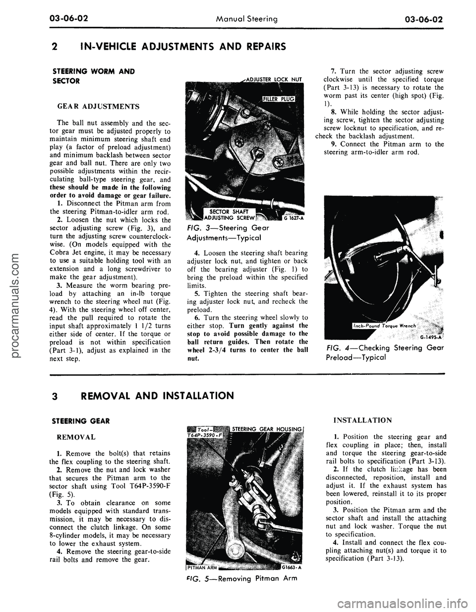
sector adjusting screw (Fig. 3), and
turn the adjusting screw counterclock-
wise.
(On models equipped with the
Cobra Jet engine, it may be necessary
to use a suitable holding tool with an
extension and a long screwdriver to
make the gear adjustment).
3.
Measure the worm bearing pre-
load by attaching an in-lb torque
wrench to the steering wheel nut (Fig.
4).
With the steering wheel off center,
read the pull required to rotate the
input shaft approximately 1 1/2 turns
either side of center. If the torque or
preload is not within specification
(Part 3-1), adjust as explained in the
next step.
.•ADJUSTER
LOCK
NUT
SECTOR
SHAFT
ADJUSTING
SCREW
G
1627-A
FIG. 3—Steering Gear
Adjustments—Typical
4.
Loosen the steering shaft bearing
adjuster lock nut, and tighten or back
off the bearing adjuster (Fig. 1) to
bring the preload within the specified
limits.
5.
Tighten the steering shaft bear-
ing adjuster lock nut, and recheck the
preload.
6. Turn the steering wheel slowly to
either stop. Turn gently against the
stop to avoid possible damage to the
ball return guides. Then rotate the
wheel 2-3/4 turns to center the ball
nut.
7.
Turn the sector adjusting screw
clockwise until the specified torque
(Part 3-13) is necessary to rotate the
worm past its center (high spot) (Fig.
1).
8. While holding the sector adjust-
ing screw, tighten the sector adjusting
screw locknut to specification, and re-
check the backlash adjustment.
9. Connect the Pitman arm to the
steering arm-to-idler arm rod.
G-1495-A
FIG. 4—Checking Steering Gear
Preload—Typical
REMOVAL AND INSTALLATION
STEERING GEAR
REMOVAL
1.
Remove the bolt(s) that retains
the flex coupling to the steering shaft.
2.
Remove the nut and lock washer
that secures the Pitman arm to the
sector shaft using Tool T64P-3590-F
(Fig. 5).
3.
To obtain clearance on some
models equipped with standard trans-
mission, it may be necessary to dis-
connect the clutch linkage. On some
8-cylinder models, it may be necessary
to lower the exhaust system.
4.
Remove the steering gear-to-side
rail bolts and remove the gear.
Too /-MB
STEERING
GEAR
HOUSING
T64P-3590.F
(PITMAN
"APU'^M
-
.-. •
-"
•.:,.17''i.a—
r.iMI.
A
F'G.
5—Removing Pitman Arm
INSTALLATION
1.
Position the steering gear and
flex coupling in place; then, install
and torque the steering gear-to-side
rail bolts to specification (Part 3-13).
2.
If the clutch linkage has been
disconnected, reposition, install and
adjust it. If the exhaust system has
been lowered, reinstall it to its proper
position.
3.
Position the Pitman arm and the
sector shaft and install the attaching
nut and lock washer. Torque the nut
to specification.
4.
Install and connect the flex cou-
pling attaching nut(s) and torque it to
specification (Part 3-13).procarmanuals.com
Page 141 of 413
03-07-03
Ford Design Non-Integral Power Steering System
03-07-03
5.
Lower the vehicle and disconnect
the fluid return hose from the reser-
voir.
6. Disconnect the fluid pressure
hose from the pump outlet fitting.
7.
Remove 1 bolt attaching the
hoses,
insulator, and the retainer to
the frame side rail and remove the
hoses,
and the insulator and retainer
as an assembly from the vehicle.
8. Remove the pressure and return
hoses from the retainer and insulator.
INSTALLATION
1.
Install the pressure and return
hoses in the insulator and retainer.
Paint stripe on pressure hose must be
aligned with slot in insulator. Paint or
tape band on return hose must be cen-
tered in insulator. Position the assem-
bly to the frame side rail and install
the attaching bolt.
2.
Place a hose clamp on the fluid
return hose and install the hose on the
power steering pump reservoir return
fitting.
3.
Torque the pump outlet fitting to
specification (Part 3-13). Then, con-
nect the pressure hose to the outlet fit-
ting and torque the fitting to specifica-
tion.
4.
Raise the vehicle and connect the
pressure and return lines to the con-
trol valve.
5.
Install the clamp to retain the
hose tubes to the control valve.
6. Lower the vehicle and fill the
power steering pump reservoir with
fluid, C1AZ-19582-A, to the proper
level (Part 3-1).
7.
Start the engine and turn the
steering wheel to each end of its travel
several times to cycle the system.
Then, check for fluid leaks.
8. Stop the engine and again check
the power steering fluid level (Part
3-1). Add fluid as required.
REMOVAL AND INSTALLATION
HOISTING INSTRUCTIONS
Damage to suspension and/or steer-
ing linkage components may occur if
care is not exercised when positioning
the hoist adapters of 2 post hoists
prior to lifting the vehicle.
If a 2 post hoist is used to lift the
vehicle, place the adapters under the
front suspension lower arms. Do not
allow the adapters to contact the
steering linkage.
STEERING GEAR
Refer to Group 3-6, Section 3 for
detailed instructions.
POWER STEERING PUMP
Refer to Group 3-10, Section 3 for
detailed instructions.
POWER STEERING CONTROL
VALVE
REMOVAL
1.
Disconnect the 4 fluid line fit-
tings at the control valve, and drain
the fluid from the lines. Turn the front
wheels to the left and right several
times to force all the fluid from the
system.
2.
Loosen the clamping nut and
bolt at the right end of the sleeve.
3.
Remove the roll pin from the
steering arm-to-idler arm rod -through
the slot in the sleeve.
4.
Remove the control valve ball
stud nut.
5.
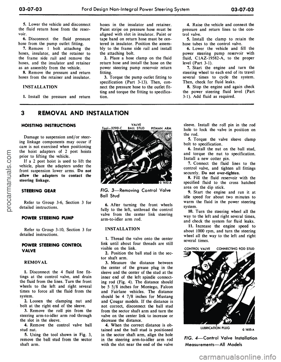
Using the tool shown in Fig. 3,
remove the ball stud from the sector
shaft arm.
VALVE
Too/-3290-C BALL STUD PITMAN ARM
FIG. 3—Removing Control Valve
Ball Stud
6. After turning the front wheels
fully to the left, unthread the control
valve from the center link steering
arm-to-idler arm rod.
INSTALLATION
1.
Thread the valve onto the center
link until about four threads are still
visible on the link.
2.
Position the ball stud in the sec-
tor shaft arm.
3.
Measure the distance between
the center of the grease plug in the
sleeve and the center of the stud at the
inner end of the left spindle connect-
ing rod (Fig. 4). The distance should
be 5 5/8 inches for Montego, Falcon
and Fairlane vehicles. The distance
should be 4 7/8 inches for Mustang
and Cougar models. If the distance is
not correct, disconnect the ball stud
from the sector shaft arm and turn the
valve on the center link to increase or
decrease the distance.
4.
When the correct distance is ob-
tained and the ball stud is positioned
in the sector shaft arm, align the hole
in the steering arm-to-idler arm rod
with the slot near the end of the valve
sleeve. Install the roll pin in the rod
hole to lock the valve in position on
the rod.
5.
Torque the valve sleeve clamp
bolt to specification.
6. Install the nut on the ball stud,
and torque the nut to specification.
Install a new cotter pin.
7.
Connect the fluid lines to the
control valve, and tighten all fittings
securely. Do not over-tighten.
8. Fill the fluid reservoir with the
specified fluid to the cross hatched
area on the dip stick.
9. Start the engine and run it at
idle speed for about two minutes to
warm the fluid in the power steering
system.
10.
Turn the steering wheel all the
way to the left and right several times,
and check the system for fluid leaks.
11.
Increase the engine speed to
about 1000 rpm, and turn the steering
wheel all the way to the left and right
several times.
CONTROL VALVE CONNECTING ROD STUD
LUBRICATION PLUG
G1653-A
FIG. 4—Control Valve Installation
Measurements—All Modelsprocarmanuals.com
Page 385 of 413
07-04-16
C-6 Automatic Transmission
07-04-16
INSTALLATION—
THUNDERBIRD
1.
Torque the two converter drain
plugs to specification.
2.
Install the converter on the sta-
tor support.
3.
Secure the transmission on a
transmission jack.
4.
Rotate the converter so that the
studs and drain plugs are in alignment
with their holes in the flywheel.
5.
Move the transmission toward
the cylinder block until they contact
each other. Install and torque the at-
taching bolts to specification. Before
tightening the center bolt on the left
side,
make sure that the accelerator
linkage stop bracket is properly posi-
tioned so that the left upper bolt may
be installed later.
6. Connect the fluid cooler lines to
their fittings on the right side of the
transmission.
7.
Raise the transmission and in-
stall the engine rear support and tor-
que the bolts to specification. Make
sure that the hand brake equalizer is
positioned properly.
8. Lower the transmission and re-
move the jack.
9. Install the engine rear support-
to-extension housing attaching bolts.
10.
Install the drive shaft.
11.
Connect the speedometer cable
to the extension housing.
12.
Position the starting motor on
the converter housing and secure it
with the two lower bolts.
13.
Install the torque converter-
to-flywheel attaching nuts and torque
them to specification.
14.
Install the converter housing
dust shield.
15.
Secure the frame side rail sup-
port brace with the attaching bolts
and lock washers. Torque the bolts to
specification.
16.
Connect the downshift rod to
the transmission downshift lever.
17.
Connect the vacuum diaphragm
hose to the upper end of the vacuum
tube.
18.
Using Tool T67P-7341-A, in-
stall a new grommet in the manual
lever. Then, secure the manual selec-
tor rod to the lever.
19.
Position the vibration absorber
to the transmission extension housing
and secure it with the three attaching
bolts.
20.
Connect the muffler inlet pipes
to the exhaust manifolds.
21.
Lower the vehicle and install
the two converter housing upper bolts
and torque them to specification.
22.
Install the starting motor upper
bolt.
23.
Place a new O-ring on the end
of the fluid filler tube and insert it in
the transmission case. Secure the tube
to the rear of the right cylinder head
with the attaching screw and lock
washer.
24.
Fill the transmission to the
proper level with the specified fluids.
25.
Adjust the manual and throttle
linkage as required.
REMOVAL-
CONTINENTAL MARK III
1.
Working from the engine com-
partment, lift the fluid filler tube dio-
stick from the transmission.
2.
Raise the vehicle on a hoist or
stands.
3.
Remove the dust shield from the
front lower end of the converter hous-
ing.
4.
Crank the engine until one of the
converter drain plugs is accessible.
Then, remove the plug.
5.
Crank the engine until the other
plug is at the bottom. Place a drain
pan to catch the fluid, then remove
the pan and allow the fluid to drain.
6. Remove the driveshaft.
7.
Remove the frame side rail sup-
port brace attaching bolts and remove
the brace.
8. After the fluid has been drained
from the converter, install the plug.
9. Place the drain pan under the
transmission pan and loosen the at-
taching bolts and allow the fluid to
drain. Finally remove all of the pan
attaching bolts except two, to allow
the oil to further drain. After the fluid
has drained, install two bolts on the
opposite side of the pan to temporari-
ly hold it in place.
10.
Remove the. converter-
to-flywheel attaching nuts.
11.
Disconnect the downshift link-
age from the transmission downshift
lever.
12.
Using tool T67P-7341-A, re-
move the selector rod from the manu-
al lever.
13.
Remove the two screws that at-
tach the shift rod bellcrank bracket to
the converter housing and remove the
bracket.
14.
Disconnect the vacuum dia-
phragm hose at the transmission.
15.
Disconnect the speedometer
cable from the extension housing and
place it to one side.
16.
Remove the two idler arm
bracket retaining bolts at the frame
side rail and allow the linkage to
hang.
17.
Disconnect the starter cable
from the terminal on the starter. Re-
move the starter attaching bolts and
remove it from the housing.
18.
Remove the clip securing the oil
cooler lines to the support bracket.
19.
Disconnect the two oil cooler
lines from the right side of the trans-
mission.
20.
Disconnect the muffler inlet
pipes at the exhaust manifolds and
allow the pipes to hang.
21.
Remove the vibration absorber
from the extension housing.
22.
Remove the engine rear support
to extension housing attaching bolts.
23.
Place a transmission jack under
the transmission and raise it just
enough to remove the weight from the
support.
24.
Remove the two support attach-
ing bolts and remove the support.
25.
Lower the jack and secure the
transmission to the jack with a safety
chain.
26.
Remove the bolt that secures
the filler tube to the rear of the right
cylinder head and lift the tube from
the transmission case.
27.
Remove the six converter
housing-to-cylinder block attaching
bolts.
28.
Carefully lower the transmis-
sion and remove it from under the ve-
hicle.
29.
Remove the converter and
mount the transmission in a holding
fixture.
INSTALLATION—
CONTINENTAL MARK III
1.
Torque the two converter drain
plugs to specification.
2.
Install the converter on the sta-
tor support.
3.
Secure the transmission on a
transmission jack.
4.
Rotate the converter so that the
studs and drain plugs are in alignment
with their holes in the flywheel.
5.
Move the transmission toward
the cylinder block until they contact
each other. Install and torque the at-
taching bolts to specification
6. Remove the jack safety chain
from the transmission.
7.
Connect the fluid cooler lines to
their fittings on the right side of the
transmission.
8. Install a new O-ring on the lower
end of the fluid filler tube. Dip the
O-ring in clean automatic transmis-
sion fluid and insert the tube in the
transmission case. Install the attach-
ing bolt.procarmanuals.com
Page 387 of 413
07-04-18
C-6 Automatic Transmission
07-04-18
16.
Position the manual and down-
shift control rod splash shield to the
frame side rail and secure it with the
attaching bolts.
17.
Connect the speedometer cable
to the extension housing.
18.
Connect the vacuum hose to the
vacuum diaphragm and secure with a
clamp.
19.
Connect the two oil cooler lines
to the fittings on the right side of the
case.
20.
Install the cooler lines under
the clip at the cylinder head.
21.
Position the reinforcement plate
and torque the attaching bolts.
22.
Install the equalizer and park-
ing brake cables. Install the equalizer
lever retracting spring.
23.
Install the drive shaft.
24.
Install a new seal on the filler
tube and install it in the transmission
case.
Secure the filler tube to the cyl-
inder head.
25.
Install the starting motor and
connect the cable.
26.
Install the idler arm bracket-
to-frame side rail.
27.
Lower the vehicle.
28.
Fill the transmission to the cor-
rect level with the specified fluid.
29.
Adjust the manual and throttle
linkage as required.
MAJOR REPAIR OPERATIONS
DISASSEMBLY OF
TRANSMISSION
1.
Mount the transmission in hold-
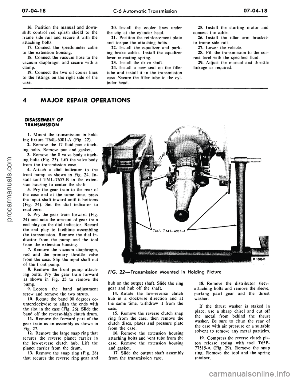
ing fixture T64L-6001-A (Fig. 22).
2.
Remove the 17 fluid pan attach-
ing bolts. Remove pan and gasket.
3.
Remove the 8 valve body attach-
ing bolts (Fig. 23). Lift the valve body
from the transmission case.
4.
Attach a dial indicator to the
front pump as shown in Fig. 24. In-
stall tool T61L-7657-B in the exten-
sion housing to center the shaft.
5.
Pry the gear train to the rear of
the case and at the same time, press
the input shaft inward until it bottoms
(Fig. 24). Set the dial indicator to
read zero.
6. Pry the gear train forward (Fig.
24) and note the amount of gear train
end play on the dial indicator. Record
the end play to facilitate assembling
the transmission. Remove the dial in-
dicator from the pump and the tool
from the extension housing.
7.
Remove the vacuum diaphragm,
rod and the primary throttle valve
from the case. Slip the input shaft out
of the front pump.
8. Remove the front pump attach-
ing bolts. Pry the gear train forward
as shown in Fig. 25 to remove the
pump.
9. Loosen the band adjustment
screw and remove the two struts.
10.
Rotate the band 90 degrees co-
unterclockwise to align the ends with
the slot in the case (Fig. 26). Slide the
band off the reverse-high clutch drum.
11.
Remove the forward part of the
gear train as an assembly as shown in
Fig. 27.
12.
Remove the large snap ring that
secures the reverse planet carrier in
the low-reverse clutch hub. Lift the
planet carrier from the drum.
13.
Remove the snap ring (Fig. 28)
that secures the reverse ring gear and
D16Q3-B
FIG. 22—Transmission Mounted in Holding Fixture
hub on the output shaft. Slide the ring
gear and hub off the shaft.
14.
Rotate the low-reverse clutch
hub in a clockwise direction and at
the same time, withdraw it from the
case.
15.
Remove the reverse clutch snap
ring from the case, then remove the
clutch discs, plates and pressure plate
from the case.
16.
Remove the extension housing
attaching bolts and vent tube from the
case.
Remove the extension housing,
and gasket.
17.
Slide the output shaft assembly
from the transmission case.
18.
Remove the distributor sleeve
attaching bolts and remove the sleeve,
parking pawl gear and the thrust
washer.
If the thrust washer is staked in
place, use a sharp chisel and cut off
the metal from behind the thrust
washer. Be sure to clean the rear of
the case with air pressure or a suitable
solvent to remove any metal particles.
19.
Compress the reverse clutch pis-
ton release spring with tool T65P-
77515-A (Fig. 29). Remove the snap
ring. Remove the tool and the spring
retainer.procarmanuals.com